patent · US5128848
Operating light
7 July 1992
Page 1 — bibliographic record
United States Patent (19) (11) Patent Number: 5,128,848 Enders et al. 45) Date of Patent: Jul. 7, 1992 (54) OPERATING LIGHT 847 131 8/1952 Fed. Rep. of Germany,
(75) Inventors: Peter Enders, Frankfurt; Jörg 10341 16 7/1958 Fed. Rep. of Germany . Hartge, Darmstadt; Ingo Jaeckel, 117964. 10/1964 Fed. Rep. of Germany . Hamburg; Reinhard Luger, 1447075 l/1968 Fed. Rep. of Germany . Offenbach; Géze Ambrus, 1287032 1/1969 Fed. Rep. of Germany . Hammersbach, all of Fed. Rep. of 1622.028 O/1970 Fed. Rep. of Germany . Germany 2305666 8/1974 Fed. Rep. of Germany.
(73) Assignee: W.C. Heraeus GmbH, Hanau, Fed. 2.535556 2/1976 Fed. Rep. of Germany . Rep. of Germany 25.9426 8/1976 Fed. Rep. of Germany .
(21) Appl. No.: 501,615 322250 12A982 Fed. Rep. of Germany . 22 Filed: Mar. 29, 1990 2725428 12/1983 Fed. Rep. of Germany .
(30) Foreign Application Priority Data 28 7903 7A988 Fed. Rep. of Germany . Mar. 31, 1989 (DE) Fed. Rep. of Germany ... 8903955(U) 7.99964 6/1936 France . Mar. 31, 1989 (DE) Fed. Rep. of Germany ... 890.3957(U) 967964. 11950 France .
51) Int. Cl. ................................................ F21V 7/02 282209 4952 Switzerland . 52 U.S. Cl. .................................... 362/268; 362/297; 337303 5/1959 Switzerland ........................ 362/804 362/299; 362/302; 362/309; 362/332; 362/339 507638 9/1939 United Kingdom . 58) Field of Search ............... 362/804, 293,268, 297, 735732 8/1955 United Kingdom ................ 362/804 362/298, 299, 302, 308, 309, 332, 339 813721 5/1959 United Kingdom .
Primary Examiner-Ira S. Lazarus
Assistant Examiner-Sue Hagarman 1822,076 9/1931 Bauersfeld et al. ................. 362/298 Attorney, Agent, or Firm-Merchant & Gould, Smith, 2,173,325 9/1939 Alexander ........ ... 24.0/1.4 Edell, Welter & Schmidt 2.257.88) 10/1941 Jaros ....................................... 240A 3,255,342 6/1966 Seitz et al. ... ... 240/14 (57) ABSTRACT 3,494,693 2/1970 Elmer .................................... 353/55 Given is an operating light, with one or several spot 3,5 .983 5/1970 Dorman ... ... 240/41.15 lights, each with a light source, that is shielded by a 3,766.377 10/1973 Junginger ......... . . 240W41.15 counter reflector in the direction of radiation. The 4,037,096 7/1977 Brendgord et al. ................. 240/4 stream of light is focused by the counter reflector and a 4,092,705 5/1978 Hogberg ............................. 362/294 reflector onto an optical system closing off the housing 4,135,231 1/1979 Fisher .................................. 362/269 in the direction of radiation. To guarantee a homogene 4,254,455 3/1982 Neal, Jr. .............................. 362/804 ous illumination of deeper surgical wounds also, the 4.463,410 7/1984 Mori.................................... 362.299 optical system is structured as a Fresnel lens made up of 4,495,552 l/1985 Graff ................................... 362/.297 annular prisms that contain a dioptric central region and 4,617,619 10/1986 Gehly .................................. 362/804 a catadioptric edge (rim) region. The slope of the flanks 4,630, 184 12/1986 Ferraro ............................... 362/293 4,700,278 10/1987 Chew .... ... 362/249 and the height of the annular prisms are dimensioned 4,755,916 7/1988 Collins .. ... 362/.298 such that the light beams emanating from the Fresnel 4,823,246 4/1989 Dilouya ............................... 362/.297 lens cut the optical axis at a distance that is all the 4,937,715 6/1990 O'Shea et al. ....................... 362/804 greater the shorter the distance with which the light beams emanate from the Fresnel lens is away from the
FOREIGN PATENT DOCUMENTS optical axis.
603666 10/1934 Fed. Rep. of Germany . 21 Claims, 7 Drawing Sheets
Page 2
Drawing sheet — no readable text.
Page 3
Drawing sheet — no readable text.
Page 4
Drawing sheet — no readable text.
Page 5
Drawing sheet — no readable text.
Page 6
Drawing sheet — no readable text.
Page 7
Drawing sheet — no readable text.
Page 8
Drawing sheet — no readable text.
Page 9
The advantages of the invention lie particularly in the
OPERATING LIGHT fact that the focal point of the different light beams generated by the Fresnel lens lie at a different distance .
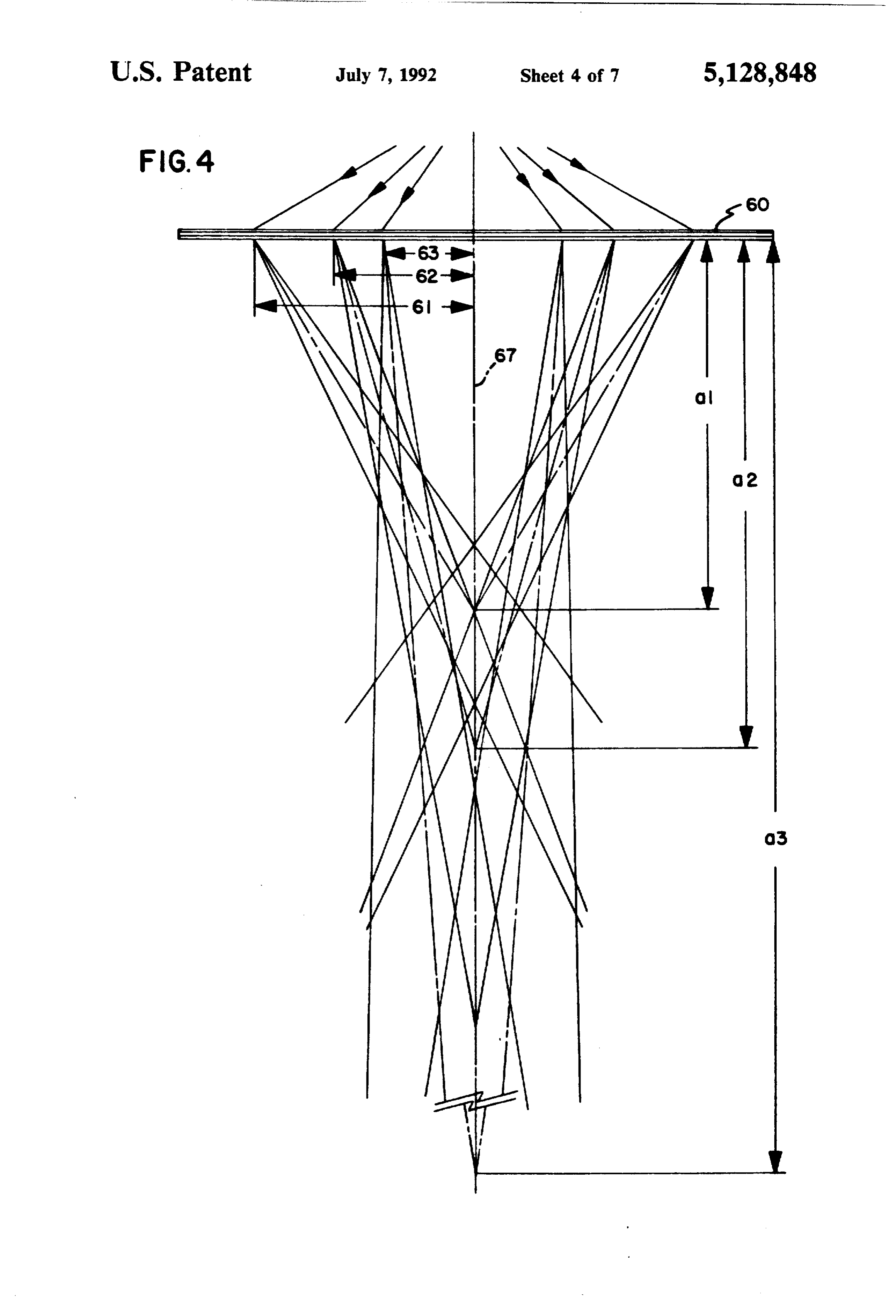
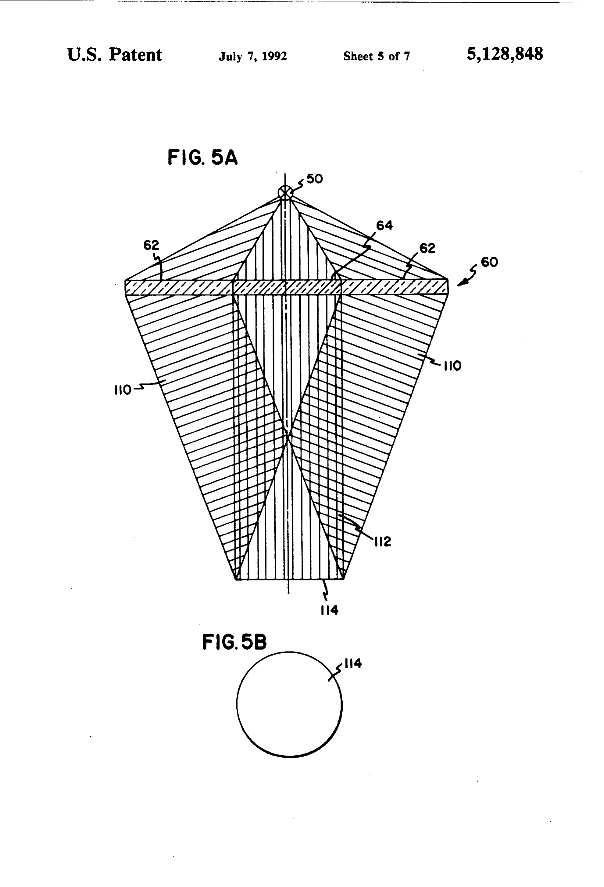
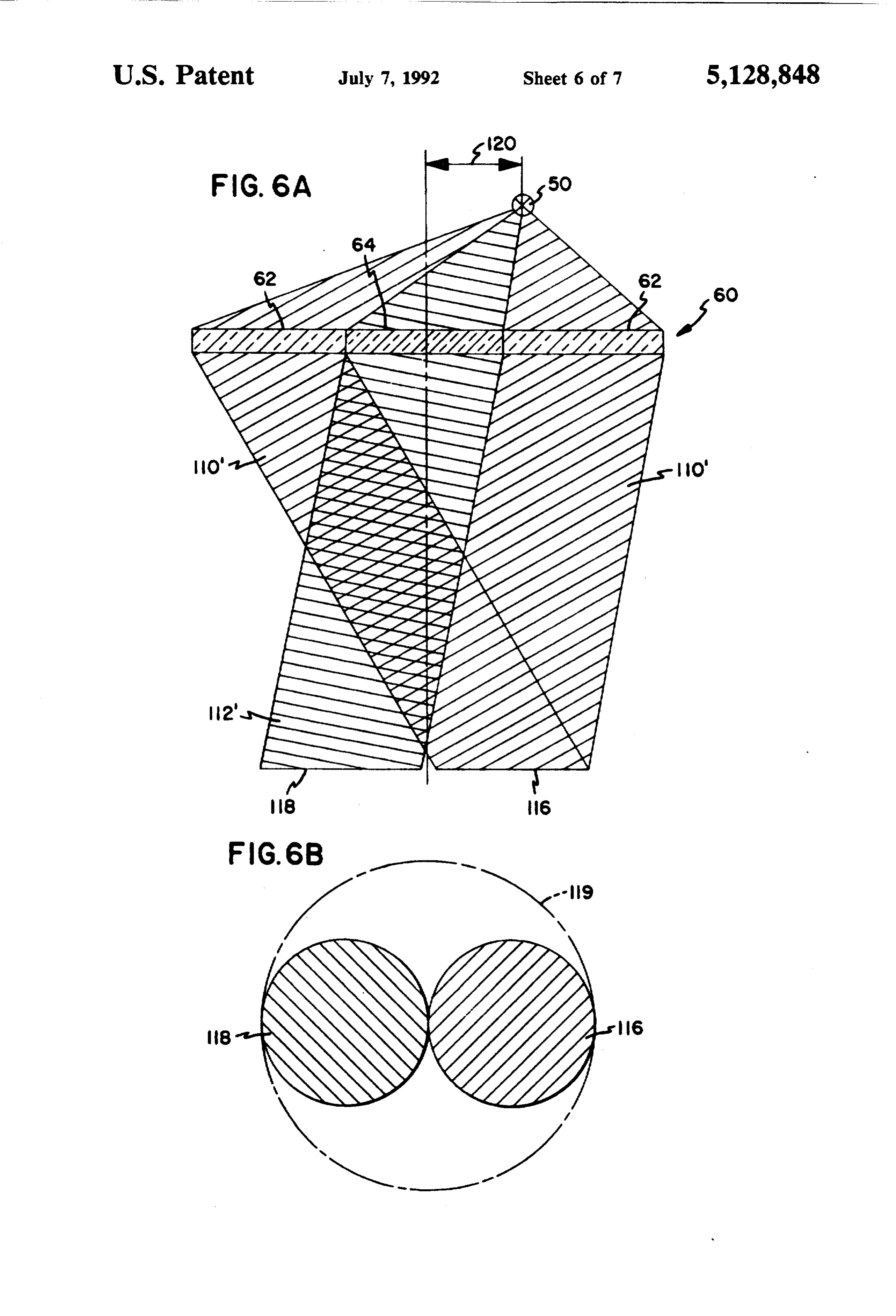
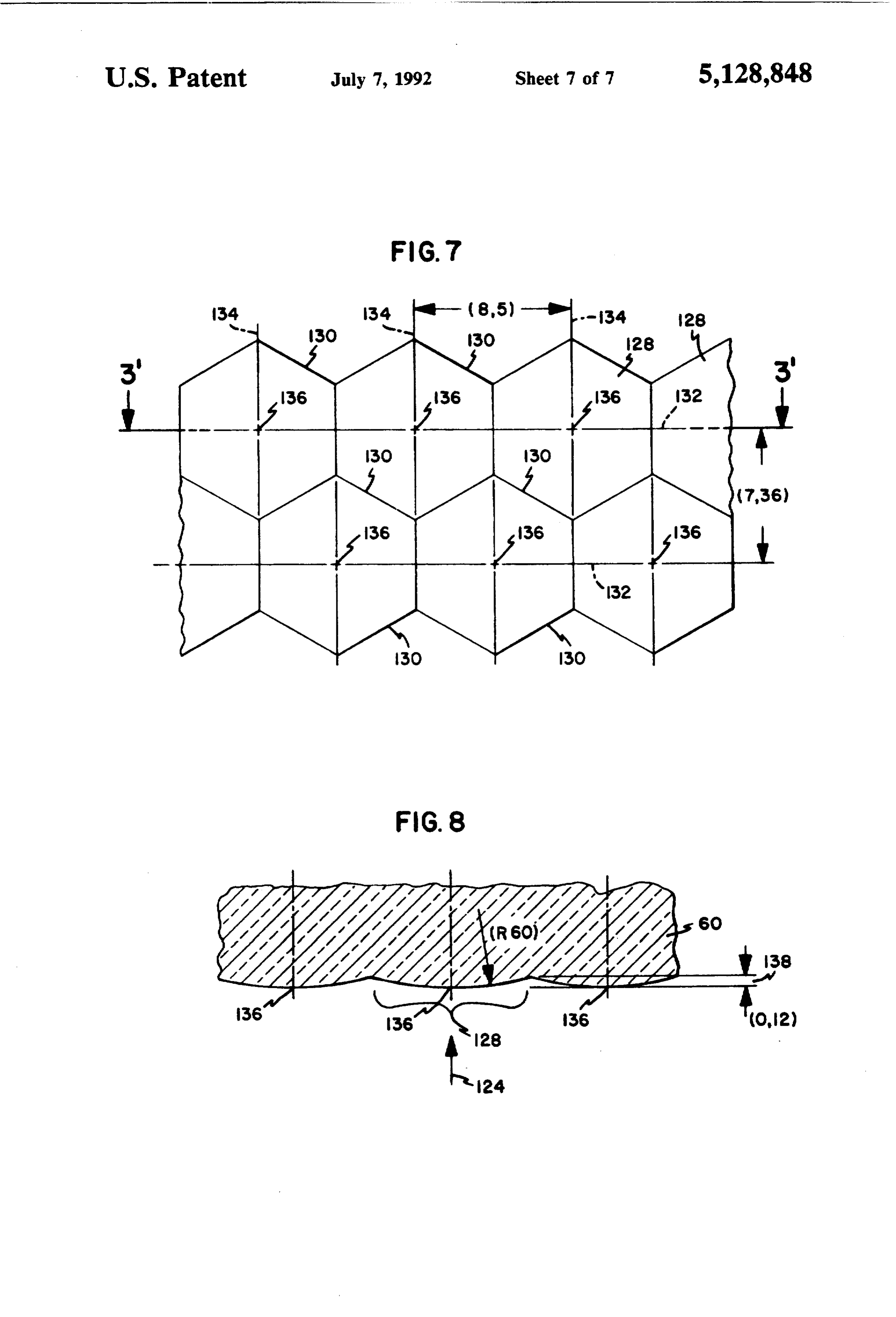
DESCRIPTION from the Fresnel lens. The light beams generated by the This invention concerns an operating light with one that light source(s) and the Fresnel lens are directed such or several spot-lights, each with a light source that is Fresnel there results, in a wide range of distances from the shielded in the direction of radiation by a counter whose light lens, an approximately parallel cone of light reflector such that the stream of light is focused by a wound remains distribution in the region of the surgical reflector onto an optical system closing off the housing O different working approximately homogeneous even with in the direction of radiation. distances. Guaranteed by the inven tion is a good shading,
Large operating lights with a light source, possibly nation of the wound cavity, depth shading and depth illuni with a counter-reflector, and with a large reflector, are The homogeneous distribution over a great working depth. described, for example, in U.S. Pat. Nos. 4,135,231 or constant shadow generation ofof the light provides for a working range, 4,037,096. These lights attain the required freedom from 15 which is essential for the work of the surgeon shadows by the reflector having a large diameter, to enable stereoscopic vision and, therewith, aninestima order which assumes the size of the entire housing. To be differentiated from these operating lights are those that tionPreferably, of the smallest distances, even in a wound cavity.
the reflector is constructed as a flat hy display several individual spotlights in a convex under perboloid in order to achieve an extremely flat method side of the light body, as are described, for example, in of construction. The reflection coating is preferably Germany Patent 847,131 or Germany Patent 2,725,428. deposited on a glass body and structured such that it It is to these types of operating lights with several indi vidual spotlights or to an individually-usable, single substantially reflects visible light, and on the other hand spotlight in a physicians light, or in an auxiliary light, substantially permits infrared radiation to pass through. that the present invention relates. Operating lights with Fresnel lens. Theonly
In this manner, visible light is irradiated onto the infrared radiation is eliminated from several individual spotlights are also called "multiple the working region of the operating light. eye lights". In order to compensate for the greater-scattering There are various proposals for improving the stream angle of radiation at the edge of the reflector, of visible of light from an operating light by influencing the light light reflected onto the inner surface of the reflector, by itself, or by optical means in the beam path between the an angle that is better directed toward the rim area of electrical source of light and the exiting light. the Fresnel lens located thereunder, the reflection coat Thusly described in U.S. Pat. No. 3,255,342 is a single ing at the edge (rim) of the reflector is preferably depos spotlight in a multiple-eye operating light, wherewith ited thicker than at the apex of the reflector. direct radiation from the lamp is prevented by a menis The Fresnel lens in accordance with the invention cus mirror-coating of the lamp. All radiation from the 35 can be of acrylic glass or similar material that is sprayed lamp is deflected into a cold-light reflector. A large part on or poured.
of the infrared radiation passes through the reflector Another embodiment of the invention is obtained by and the visible light is focused on an optical system a controllable mobility of the hyperboloid reflector unit closing off the housing for the light in the direction of relative to the Fresnel lens system. Achieved by this radiation. 40 mobility is an advantageous focusing capability of the This optical system consists of several disks or coat spotlight. Resulting additionally, is a homogenizing of ings, of which one disk or coating reflects or absorbs the field of illumination, if, for example, two, three or infrared in the same way. These disks or coatings make more individual spotlights of an operating light are the operating light heavy and the hot rays, not carried defocused by a like amount. The light beams formed by off, heat the operating light over a long period of opera 45 the dioptric and by the catadioptric lens portion of the tion. Even the infrared-reflecting disks pick up heat Fresnel lens then wander by like amounts from or over long periods of operation and then irradiate it. toward the optical axis, having as a consequence either Known from France Patent 967,964 is an operating a uniform expansion or narrowing of the field of illumi light having a Fresnel lens that contains only a catadi nation.
optric region and displays an adjustable source of light. SO Retained in each case by the lens system in accor Known from Germany Patent 603,666, as well as dance with the invention is the great advantage that, from Switzerland Patent 282,209, are Fresnel lenses with each adjusted size of the illuminated field of opera with dioptric and catadioptric regions. tion, a homogeneous light distribution is also set in The object of the invention is to further develop an deeper-lying regions of the wound cavity. The operat operating light of the initially-mentioned type, such that 55 ing light has a good depth sharpness, without which the an almost homogeneous illumination of a deep surgical position of the operating light need be subsequently wound is guaranteed. corrected as the operation progresses. This objective, in the case of the operating light of the Particularly preferred, the Fresnel lens is constructed initially-mentioned type, is met in accordance with the of a throughpass basic disk that displays in the rim re invention from the fact that the optical system includes gion annular prisms whose vertex rings and flanks point a Fresnel lens made of annular prisms having a dioptric toward the reflector and form the catadioptric region. central region and a catadioptric edge region, and that The basic disk likewise has in its central region annular the annular prisms are configured such that the light prisms whose apices are also directed toward the reflec beams emanating from the Fresnel lens cut the optical tor, Placed in the central region, over the basic disk, is axis at a distance from the Fresnel lens that is all the 65 a second Fresnel lens whose annular prisms are directed greater the shorter the distance with which the light away from the reflector and which, with the opposing beams emanate from the Fresnel lens is away from the ly-directed annular prisms of the throughgoing basic optical axis. disk and an air gap included therebetween, forms the
Page 10
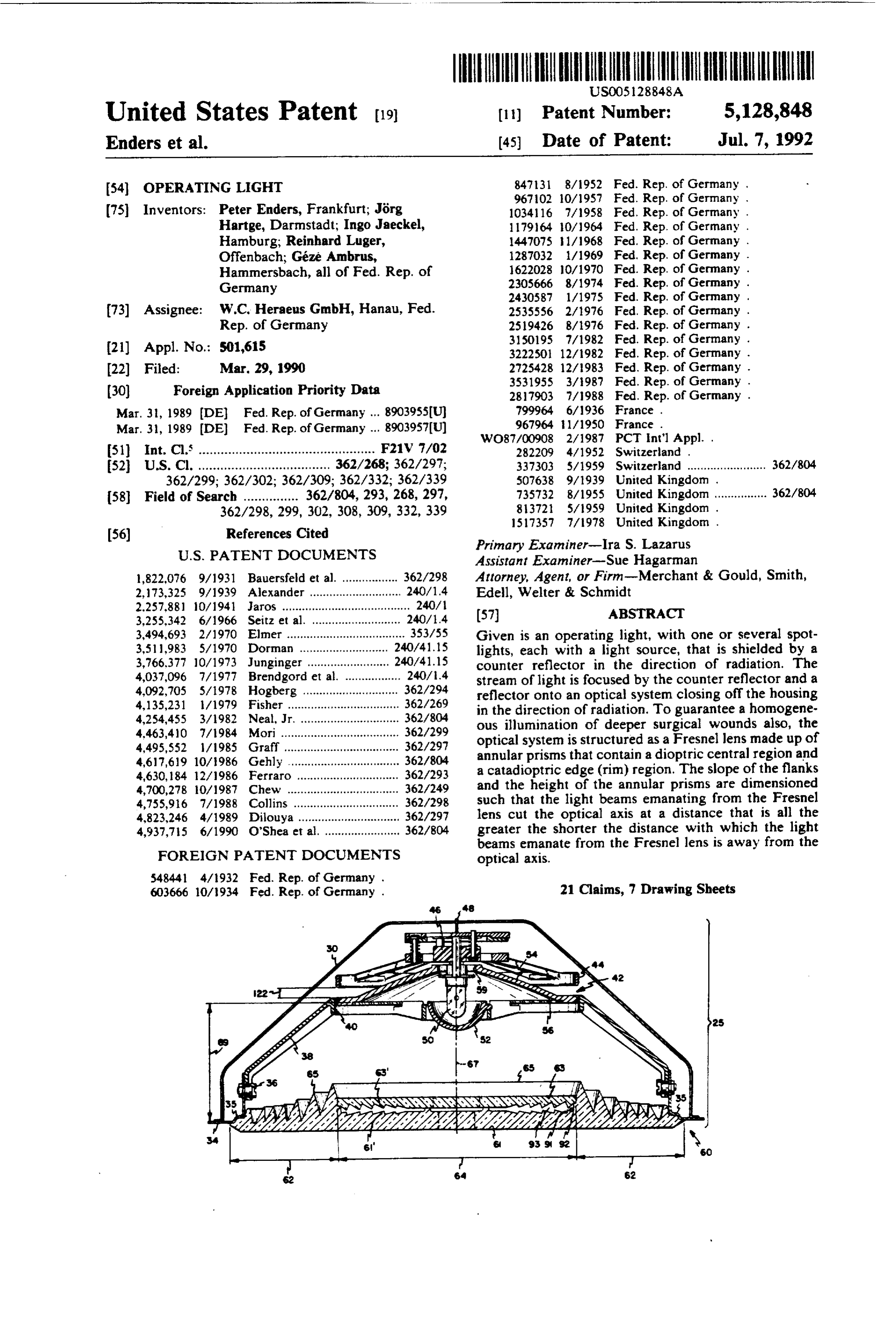
dioptric lens region. The height of the apex rings of the held very flat with a slight extension 28. In confor annular prisms of the catadioptric rim region decreases mance with the applicable state of the art of multiple with increasing distance from the optical center axis. eye operating lights, the member 26 has a lower closure The flanks of these annular prisms inclined toward the 32 in which the light outputs from individual spotlights optical axis become steeper with increasing distance 5 25 are located in an area that is arched in sphere-section from the optical center axis, while the radially-outward fashion.
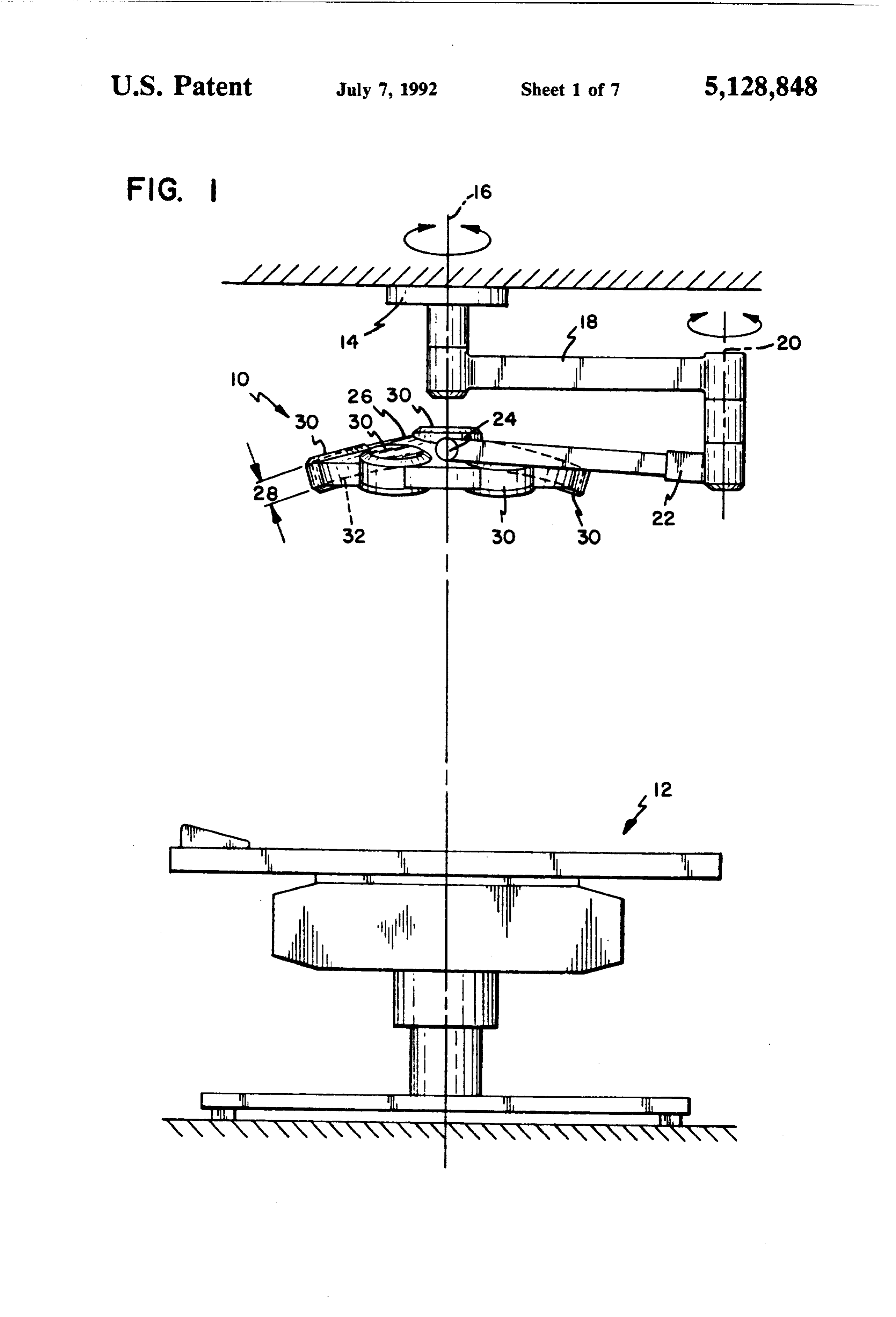
inclined flanks of these annular prisms are less inclined An operating light of the type described, can display with increasing distance from the optical center axis. one to seven individual spotlights 25, as will be de In the air gap of the dioptric central region of the scribed in more detail below with the aid of FIG. 2. Fresnel lens, the refractive flanks of the lamp-side and 10 Inside the member 26, each individual spotlight 25 is light-output-side annular prisms lie opposite to one an accessible from the top side, i.e. from the side lying other. On the lamp side, the refractive flanks lie more opposite to the light-radiating side of the member 26, toward the horizontal than they fall off on the light-out after removing a detachable cover 30, which considera put side. The refractive flanks of the annular prisms of bly simplifies replacing light sources 50, carrying out the central region of the Fresnel lens form, with increas- 15 maintenance, cleaning, adjusting, etc. ing distance to the optical center axis, a growing angle According to FIG. 2, each individual spotlight 25 toward the horizontal. Obtained by this dimensioning of displays a closed underside 34 that carries a Fresnel lens the annular prisms is that the center rays of the light 60 in a rigid skirting, described in more detail later, beam going out from the Fresnel lens intersect with the Produced via a releasable attachment 36 is a connection optical axis at a different distance from the Fresnel lens 20 to a carrier 38 that passes over into a flanged opening 40 and form corresponding focal points, whereby light in which a reflector system 42 with light source can distribution remains approximately homogeneous over Owe.
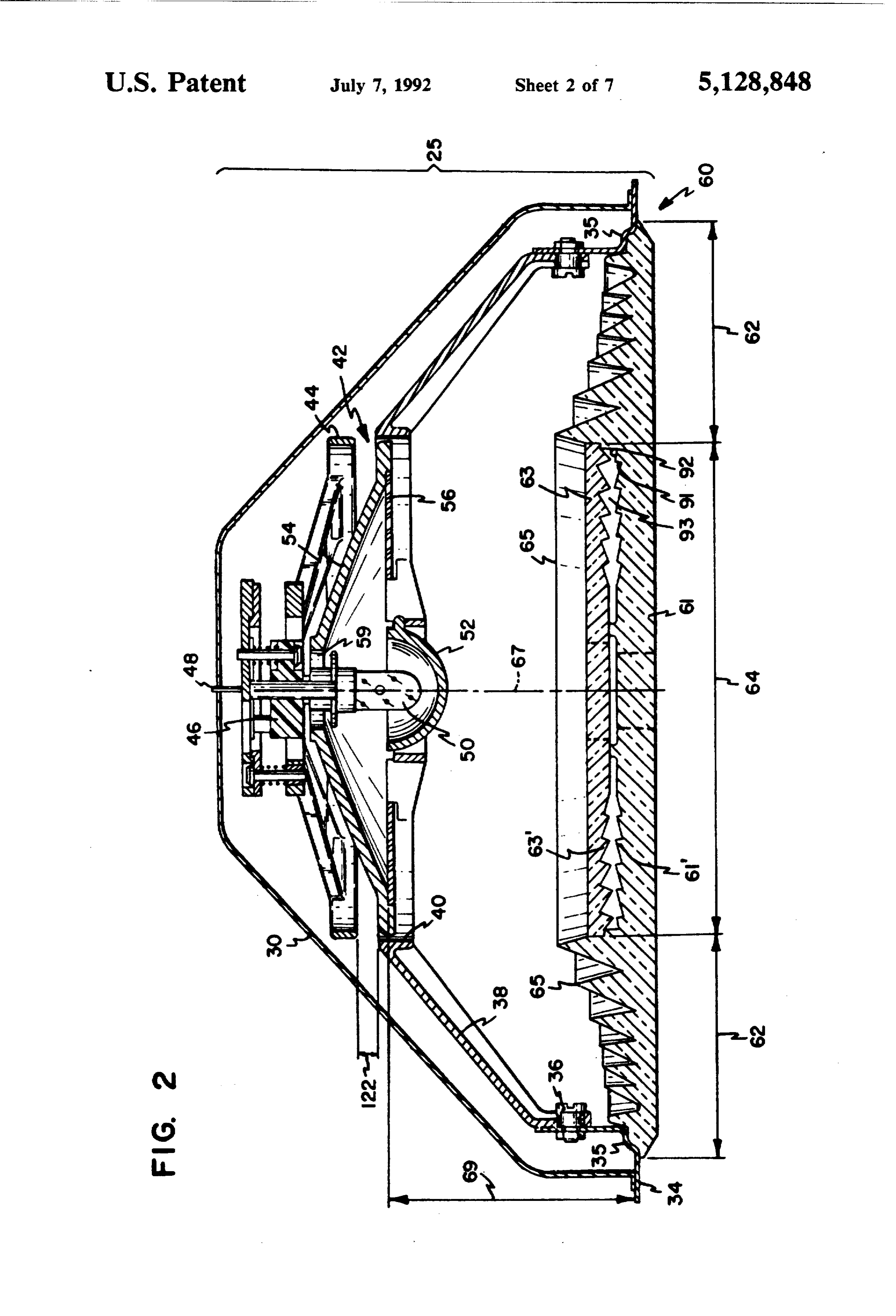
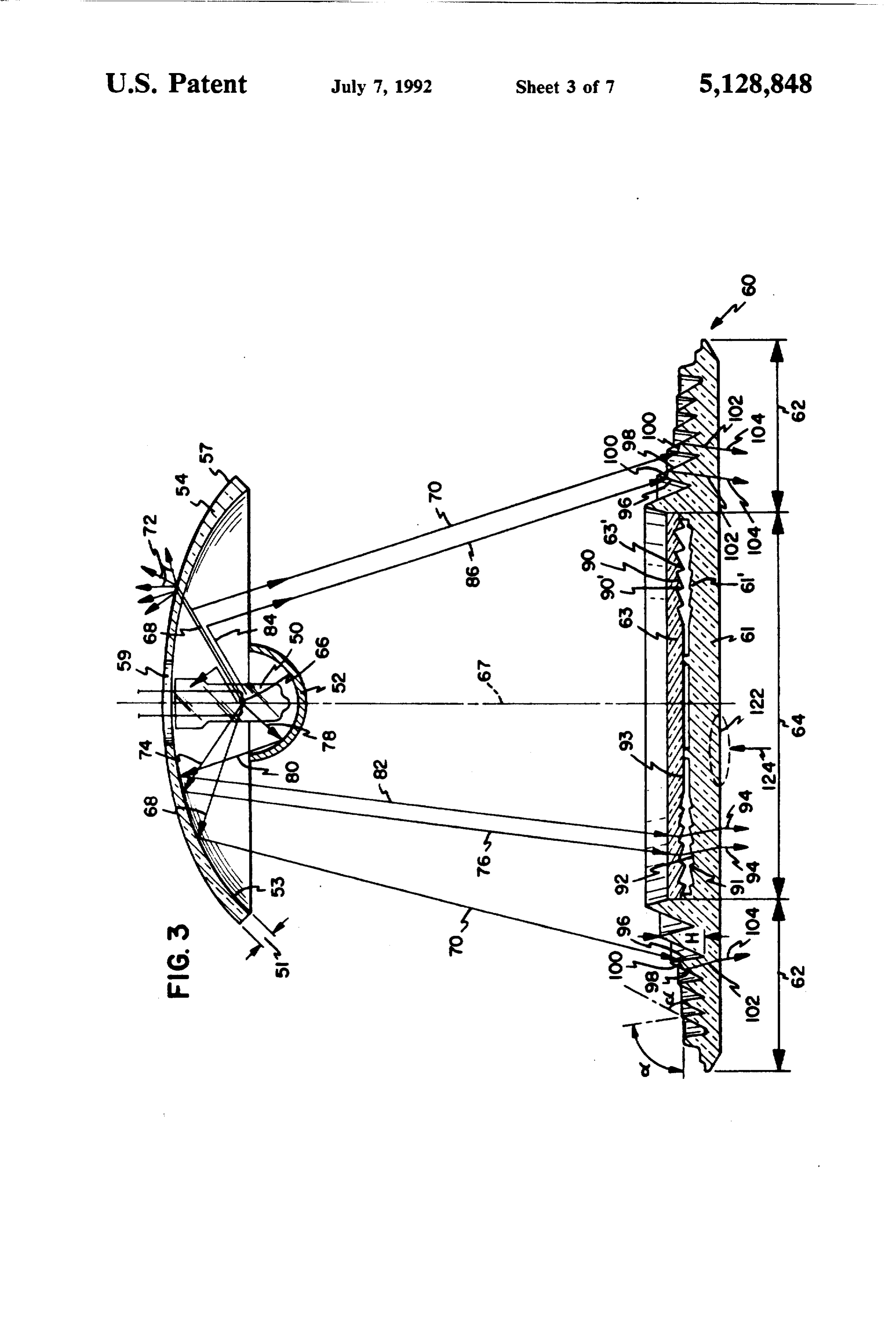
a wider distance range. The reflector system 42 consists of a carrier 44 in Particularly preferred, the lamps, the counter reflec whose center is located an adjustable mounting 46 for a tor and the reflector form a structural unit which, com- 25 light source 50, preferably a halogen lamp. The mount pared to the Fresnel lens that is rigidly joined with the ing 46 is removable from the carrier 44 for replacing the housing, is arranged in movable fashion. A movement light source 50. Brought out from the mounting 46 are of this structural unit relative to the Fresnel lens results flexible electrical connections. in an enlargement of the field of illumination, so that the The total radiation emanating from the light source surgeon, with an appropriate movement, can homoge- 30 50 is hampered from direct irradiation in the direction neously illuminate an enlarged field of operation. toward the covering disk, structured as a Fresnel lens Other particulars, features and advantages of the 60, by a counter reflector 52, and is reflected back. In present invention are obtained from the following de this manner, the preponderant portion of the radiation scription of the drawing. going out from the light source 50 strikes against a FIG. 1 shows a schematic representation of the ar- 35 principal reflector 54. This principal reflector 54 con rangement of a new operating light above an operating sists of glass and, in the form of embodiment repre table; sented, is a hyperboloid. A hyperboloid reflector has FIG. 2 shows a schematic, sectional representation of the advantage of being low and is easily produced from an individual spotlight of the new operating light; glass. The reflector 54 is smaller in diameter than the FIG, 3 shows a representation of the main radiation 40 light output area of the Fresnel lens 60. Since, however, conduction of a light source by the individual spotlight; the amount of light is collected via the smaller reflector FIG. 4 shows a schematic representation of the path 54, a high degree of depth illumination in the operating of the rays for individual light beams after passing field results, which is desirable and advantageous. through the Fresnel lens; Deposited on the inner side of the reflector 54, which FIG. 5A and 5B shows a greatly simplified represen- 45 becomes thicker toward the rim 51, is a reflection coat tation of light conduction from an individual spotlight ing 53 that is substantially pervious for infrared radia into a small illuminated field; tion and, which reflects the visible radiation toward the FIG. 6A and 6B shows a representation similar to the Fresnel lens 60, as is described in more detail in the one in FIG. 5 for light conduction from an individual following. The thickness of the reflection coating 53 spotlight into a large illuminated operating field; SO increases toward the rim of the reflector 54. FIG. 7 shows an enlarged view onto a scattering The beam generated by a coil 66 in the light source 50 structure of the Fresnel lens; and can first be filtered in the shell or wall of the light FIG. 8 shows a cut along the line 3'-' in FIG. 7. source 50. However, since a halogen lamp 50 emits a In accordance with the overview representation in large component of infrared radiation that radiates ei FIG. 1, an operating light 10 is suspended in customary 55 ther directly, like a ray 68 from the coil 66 toward the fashion above an operating table 12 by means of a ceil reflector 54, or strikes, via the counter reflector 52, like ing attachment 14, individually as represented, or in a ray 78, against the reflector 54, the reflection coating combination with other, same, larger or smaller, operat 53 is constructed as a conversion filter. While rays 68 ing lights. The suspension is formed by a swivel joint 16, are substantially (approximately 70%) deflected as visi about whose axis the light 10 can be swung by at least 60 ble light rays 70 in the direction of the Fresnel lens 60, 360. In a manner known per se, the suspension for the infrared rays 72 do pass through and are diffusedly light further consists of several arms that are joined distributed on the back side of the reflector S4 by a together by means of links. Hence, connecting to the coating 57. This diffuse distribution of the infrared rays link 16 is an arm 18 and to this arm 18, via a double link 72, that pass through on the back side of the reflector 20, an arm 22 is linked and capable of being swung 65 54, brings about that the heat rays will not strike in about its longitudinal axis, and that arm 22 carries, via beam fashion any components in the member 26 and an axle 24, a member 26 of the operating light 10. The heat them. Rather, it results in an arbitrary scattering member 26, compared to customary operating lights, is that distributes itself all over. Located in the center of
Page 11
the reflector 54 is an opening 59 wherethrough is ac cal axis 67. The corresponding flank inclination, a, complished not only the equipping with a socket for the therefore increases toward the rim of the Fresnel lens lamp 50, but also through which portions of infrared 60. The upper edges of the annular prisms 65 become rays are led away from the reflector system 42. lower toward the rim of the Fresnel lens 60 and the Another measure for filtering out undesired heat height H of the annular prisms 65 therefore decreases radiation and for generating a cold light in the operating correspondingly toward the rim, so that all radiation field is represented by the arrangement of a filter disk S6 passing in this catadioptric rim region in spite of the low (FIG. 2) at the lower edge of the reflector 54. Advanta structural height, i.e. the short distance 69 from the geously, we are dealing with an annular disk that is reflector 54 to the Fresnel lens 60, and in spite of the supported only with its radially external rim, and needs O different diameters, is diffracted into the Fresnel lens 60. no mechanical connection to the hot center made up of Likewise, the flanks 98 directed toward the operating light source 50 and counter reflector 52. Heating by axis 67 of the catadioptric prisms 65, at which a total thermal flow is avoided. The infrared radiation occur reflection occurs, become relatively flatter with in ring is reflected back upwardly at an angle that is di creasing distance from the optical axis 67, the corre rected essentially toward the opening 59. In one practi 15 sponding flank inclination, £3, therefore decreases cal example of embodiment, the largest, optically-effec toward the rim. In this manner, the spotlight attains, tive diameter of the Fresnel lens 60 comes to 190 mm, from the catadioptric region 62 of the Fresnel lens 60, a and the diameter of the reflector 54 is about 120 mm in desired ray pattern as will be laid out in more detail with the optically effective region. The distance from the the aid of FIG. 4, 5 and 6.
lower rim of the reflector 54 to the center plane of the 20 In the dioptric central region 64 of the Fresnel lens, Fresnel lens 60 now amounts to 37.7 mm. In another rays 74 coming from the coil 66 of the light source 50, larger, practical example of embodiment, the largest or rays 76, 78, 80, 82 reflected via the counter reflector optically effective diameter of the Fresnel lens 60 52 and the reflector 54, strike against the flanks 90 of the amounts to about 250 mm and the optically largest annular prisms 63' of the Fresnel disk 63 inserted diameter of the reflector lies at about 120 mm. Here, the 25 toward the incident light side. From the flanks 90 of the distance from the lower rim of the reflector 54 to the annular prisms 63' directed toward the radiating side, center plane of the Fresnel lens 60 amounts to 70 mm. the rays are deflected in the intermediate space 93 that In accordance with these two practical examples, is available subsequently used can be the same reflector unit with a throughgoingbetween the top Fresnel disk 63 and the disk 61. The rays then strike against op reflector output opening of about 120 mm and an apex 30 posingly inclined height of only about 20 mm for different sizes of indi the throughgoing flanks 92 of the annular prisms 61' of Fresnel disk 61 directed toward the vidual spotlights, which lowers the manufacturing light source 50. The inclination of oppositely-lying costs.
flanks 90 and 92 to the horizontal is in each case differ
The circular-shaped Fresnel lens 60 forming the light ent enough so that the radiation 94 from the dioptric output is larger in diameter than the reflector 54 and 35 central consists of a dioptric central region and of an annular cal axisregion 64 occurs almost axis-parallel to the opti of the Fresnel lens 60; compare in particular catadioptric rim region, which is best brought out in FIG. 4. The flanks 92 of the throughgoing Fresnel disk
FIG. S.
The light-output-side, lower part of the Fresnel lens slope61 inclined upwardly toward the optical axis have a 60, consists of a part 61 passing over the entire diameter, opticalthat increases with increasing distance from the axis 67. Likewise, the flanks 90 of the annular which, in the rim region 62 represents the sole catadiop prisms 63' tric lens system, while in the central region 64 another toward theofoptical the Fresnel disk 63 directed downwardly axis 67 display an increasing slope
Fresnel lens 63 is put on and inserted for the purpose of with increasing distance from the optical axis 67. achromatizing. The special configuration of the annular prisms 65, In the catadioptric region 62 of the Fresnel lens 60, 45 respectively 63, 61' and the selected flank slopes, a, A the light rays occurring there from the reflector 54 are cause the light beams coming from the Fresnel lens to deflected by a series of annularly-constructed prisms 65
(FIG. 3). The flank inclinations a, b and the height H of cut the optical axis 67 at a distance a from the Fresnel the annular prisms of the Fresnel lens 60 are selected lens that is all the greater the shorter the distance b, the such that in the operating field an approximately homo 50 distance between where the light beams emanate from geneous distribution of illumination intensities is ob the Fresnel lens 60 and the optical axis 67. Thus, the tained, even over a predetermined depth region, which light beams that come out at the rim of the Fresnel lens will be explained in more detail with the aid of FIG. 4. 60 are most strongly refracted toward the optical axis Hence, for example in accordance with FIG. 3, rays and cut the optical axis 67 at the distance all. The repre 68 are deflected from the reflector 54 into rays 70 such 55 sented center beam comes out from the Fresnel lens 60 that they strike against inclined surfaces 96 of the prism at the distance b2 from the optical axis and cuts the rings 65 and are diffused into the material of the Fresnel optical axis at the distance a2. The bean of light coming lens 60. Within the Fresnel lens 60, the refracted ray 100 out from the dioptric region of the Fresnel lens 60 near runs up to the back wall of the oppositely-located in the optical axis 67 at the distance b3, has an external ray clined prism surface 98 and is totally reflected there so 60 that runs almost parallel to the optical axis, the middle that these light rays 102 first run on further in the nate ray cuts the optical axis 67 at a great distance as from rial of the Fresnel lens 60, and finally come out in the the Fresnel lens 60. The distances a1, a2, a3 give the direction toward the operating field as rays 104. In the point of intersection of each center ray of the light beam same way, rays 84, from arbitrary places of the reflector of concern with the optical axis 67. Achieved by the 54, are diffracted in the direction of the ray 86 toward 65 different focusing of the different light beams is that a an inclined surface 96 of the prism rings. The outwardly homogeneous light intensity is possible over a relatively inclined flanks 96 of the catadioptric annular prisms 65 wide range of depths, and therewith, a homogeneous become steeper with increasing distance from the opti illumination of a deep surgical wound is possible. Unde
Page 12
sired variations in light distribution are to a great extent 7.36 to 8.5 mm), as compared with the diameter of the eliminated. Fresnel lens 60.
Represented schematically in FIG. 5A and 5B is the FIG. 8 shows a cut through the scattering structure homogeneity in the illuminated operating field 114 that represented in FIG. 7, along the cut axis 3'-3". The is achievable by means of the Fresnel lens 60 with its individual hexagons display a bulge 138 toward the catadioptric region 62 and dioptric region 64 for an center 136, whereby arising at the hexagonal edges 130 ideal case of exact focusing of the lamp 50 in the optical is an obtuse angle. The depth of flexure is in the magni system. Resulting under an individual spotlight 25 is a tude of 0.1 mm.
concentrically illuminated small field of operation 114, The bulge has an arc radius of 60 mm over the center by superimposing the ray guide 112 in the dioptric re 10 136. All dimensions given in the drawing of FIG. 7 and gion 64 in the center with the ray guide 110 in the cata 8 are mm-dimensions.
dioptric region 62 out from the rim. Instead of an outwardly-directed, arched honeycomb Now, in accordance with the invention, the entire structure, also capable of being made in the surface of ray-generating and reflector system 42 is movable rela 15 the Fresnel lens 60 are like down-warpings. tive to the fixed Fresnel lens 60, which is indicated in Obtained by means of several individual spotlights in FIG. 2 by a movement gap 122 and in FIG. 6 by a an operating light is a good homogeneity of the lighting lateral deflection 120 of the lamp 50. field and good depth illumination. The size of the field Should there occur in the movement gap 122 a short can be regulated with other measures. Also, contrast stroke upwardly or downwardly in the direction of the formation improves considerably by means of the new optical axis 67 of the movable system, this would mean, 20 honeycomb structure. Based on DIN 2035, shadiness as a change in the distance relative to the fixed Fresnel has been determined to be greater than 50% and deep lens system 60, a broadening or narrowing of the illumi shadiness greater than 30%.
nated field. A tilting in the direction of the displacement We claim:
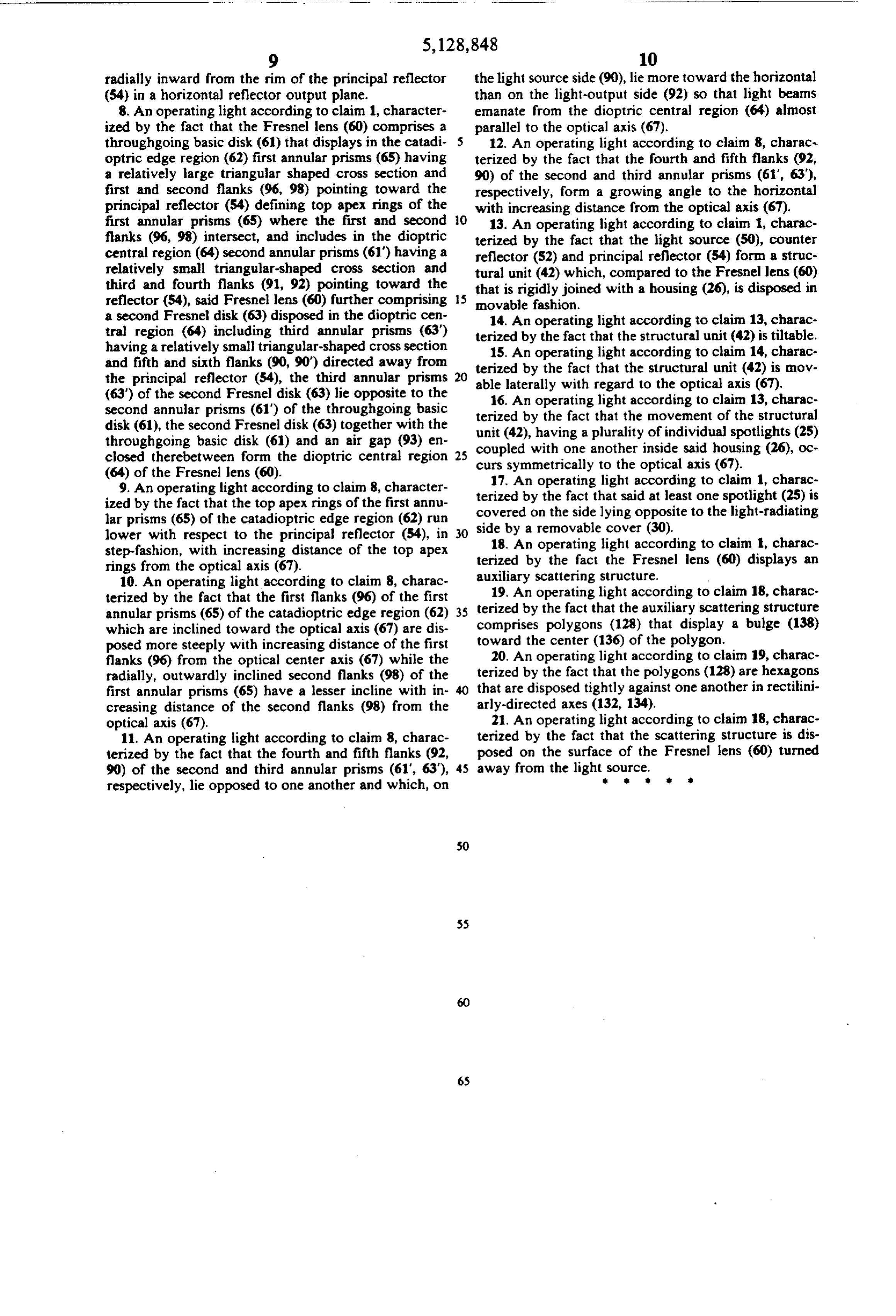
122 (FIG. 6) of the lamp 50, with its reflector system 25 1. An operation light (10) comprising at least one made up of counter reflector 52 and reflector 54 with spotlight (25), said spotlight having a light source (50) filter disk 56, would result in a pushing apart of the ray that is shielded in the direction of radiation by a counter pattern 110' in the catadioptric region 62 with a radia reflector (52), a stream of light reflected by said counter tion field 116 resulting therefrom. The radiation field reflector (52) is focused by a principal reflector (54) 118 is generated by the ray pattern 112' under the diop 30 onto an optical system closing off the spotlight in the tric region 64, FIG. 6A. When a tilting of this sort takes direction of radiation, said optical system includes a place in a three-eye operating light, an operating light Fresnel lens (60) having a dioptric central region (64) 10 with three individual spotlights 25, operating simul and a catadioptric edge region (62) centered on an opti taneously and uniformly and which can be accom cal axis (67) therethrough, said regions including annu plished by a simple mechanism, there then would result 35 lar prisms (65; 61", 63' configured such that light beams a large lighted field with an enveloping circle 119, FIG. of the stream of light emanating from the Fresnel lens 6B. Naturally, it is possible to obtain a greater homoge (60) all cut the optical axis (67) a distance (a) away from neity in the operating field with a larger number of the fresnel lens, said distance from the Fresnel Lens (60) individual spotlights 25 in an operating light, with the being greater with the shortening of the distance (b) same mutual mobility or tiltability of the lamp reflector 40 between where the light beams emanate from the Fres system 42 relative to the fixed Fresnel lens system. This nel lens (60) and where the optical axis (67) intersects type of adjustability, while retaining homogeneity of with the Fresnel lens (60).
light distribution and good depth illumination in deep 2. An operating light according to claim 1, character surgical wounds is achievable only through the combi ized by the fact that the principal reflector (54) is a nation with the Fresnel lenses. 45 hyperboloid having a reflection coating (53) deposited Instead of a smooth external surface, which when on a glass body extending from an apex to a rim. viewed from the top, produces a picture of concentric 3. An operating light according to claim 2, character rings occasioned by the Fresnel structure, the Fresnel ized by the fact that the reflection coating (53) on the lens 60 is given as a scattering layer, a honeycomb struc principal reflector (54) substantially reflects visible light ture, as becomes clear from the enlarged cutout view SO and substantially allows infrared radiation to pass there from FIG. 3 or in FIG. 7. The top view onto a section through.
122 follows in the direction of the arrow 124. Here, in 4. An operating light according to claim 3, character the representation of FIG. 7 and 8, a greatly enlarged ized by the fact that the reflection coating (S3) of the scale is used as compared to FIG. 3. While the diameter principal reflector (54) is deposited thicker at the rim of of the individual spotlight comes to about 20 to 30 cm, 55 the principal reflector than at the apex of the principal the section in F.G. 7 and/or 8 shows a width of only reflector.
about 2.6 cm. 5. An operating light according to claim 2, character It is essential that the scattering structure be small ized by the fact that the diameter of the principal reflec relative to the annular prisms 65,90, 92 of the Fresnel tor (54) is smaller than the diameter of the Fresnel lens lens 60 and that the structural limits of the scattering (60).
structure cross, in as much as possible, the structural 6. An operating light according to claim 3, character lines of the lens glass. ized by the fact that the reflection coating (53) is depos As can be seen from FIG. 7, the scattering structure ited on an inner side of the principal reflector towards consists of polygons 128. Preferably provided are hexa said light source, while an outer side of said principal gons that are disposed with their sides 130 up against 65 reflector includes a surface (57) for scattering the infra each other in rectilinearly-aligned, perpendicularly red radiation that has passed therethrough. crossing axes 132, 134. We are dealing here with a very 7. An operating light according to claim 2, character small-space structure (polygonal diameter for example ized by the fact that a filtering disk (56) which extends
Page 13
radially inward from the rim of the principal reflector the light source side (90), lie more toward the horizontal (54) in a horizontal reflector output plane. than on the light-output side (92) so that light beams 8. An operating light according to claim 1, character emanate from the dioptric central region (64) almost ized by the fact that the Fresnel lens (60) comprises a parallel to the optical axis (67). throughgoing basic disk (61) that displays in the catadi 12. An operating light according to claim 8, charact optric edge region (62) first annular prisms (65) having terized by the fact that the fourth and fifth flanks (92, a relatively large triangular shaped cross section and 90) of the second and third annular prisms (61", 63), first and second flanks (96, 98) pointing toward the respectively, form a growing angle to the horizontal principal reflector (54) defining top apex rings of the with increasing distance from the optical axis (67). first annular prisms (65) where the first and second O 13. An operating light according to claim 1, charac flanks (96, 98) intersect, and includes in the dioptric terized by the fact that the light source (50), counter central region (64) second annular prisms (61) having a reflector (52) and principal reflector (54) form a struc relatively small triangular-shaped cross section and tural unit (42) which, compared to the Fresnel lens (60) third and fourth flanks (91, 92) pointing toward the that is rigidly joined with a housing (26), is disposed in reflector (54), said Fresnel lens (60) further comprising 15 movable fashion.
a second Fresnel disk (63) disposed in the dioptric cen 14. An operating light according to claim 13, charac tral region (64) including third annular prisms (63) terized by the fact that the structural unit (42) is tiltable. having a relatively small triangular-shaped cross section 15. An operating light according to claim 14, charac and fifth and sixth flanks (90, 90') directed away from terized by the fact that the structural unit (42) is mov the principal reflector (54), the third annular prisms 20 able laterally with regard to the optical axis (67). (63) of the second Fresnel disk (63) lie opposite to the 16. An operating light according to claim 13, charac second annular prisms (61) of the throughgoing basic terized disk (61), the second Fresnel disk (63) together with the unit (42),byhaving the fact that the movement of the structural throughgoing basic disk (61) and an air gap (93) en coupled with onea another plurality of individual spotlights (25) inside said housing (26), oc closed therebetween form the dioptric central region curs symmetrically to the optical
(64) of the Fresnel lens (60). 17. An operating light according to claim 1, charac 9. An operating light according to claim 8, character terized ized by the fact that the top apex rings of the first annu coveredbyonthe fact that said at least one spotlight (25) is the side lying opposite to the light-radiating lar prisms (65) of the catadioptric edge region (62) run side by a removable cover (30). lower with respect to the principal reflector (54), in 30 18. An operating light according to claim 1, charac step-fashion, with increasing distance of the top apex rings from the optical axis (67). terized by the fact the Fresnel lens (60) displays an 10. An operating light according to claim 8, charac auxiliary scattering structure.
19. An operating light according to claim 18, charac terized by the fact that the first flanks (96) of the first terized annular prisms (65) of the catadioptric edge region (62) 35 by the fact that the auxiliary scattering structure which are inclined toward the optical axis (67) are dis comprises polygons (128) that display a bulge (138) posed more steeply with increasing distance of the first toward the center (136) of the polygon. flanks (96) from the optical center axis (67) while the 20. An operating light according to claim 19, charac radially, outwardly inclined second flanks (98) of the terized by the fact that the polygons (128) are hexagons first annular prisms (65) have a lesser incline with in that are disposed tightly against one another in rectilini creasing distance of the second flanks (98) from the arly-directed axes (132, 134).
optical axis (67). 21. An operating light according to claim 18, charac 11. An operating light according to claim 8, charac terized by the fact that the scattering structure is dis terized by the fact that the fourth and fifth flanks (92, posed on the surface of the Fresnel lens (60) turned 90) of the second and third annular prisms (61", 63), 45 away from the light source.
respectively, lie opposed to one another and which, on
Page 14
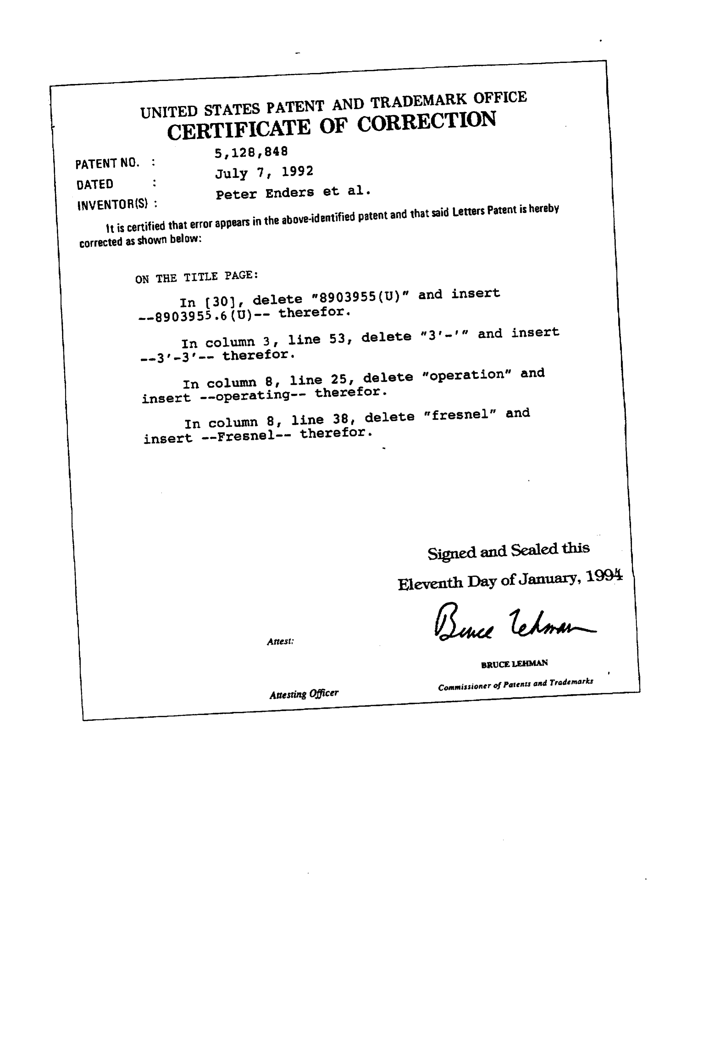
UNITED STATES PATENT AND TRADEMARK OFFICE
CERTIFICATE OF CORRECTION
it is certified that error appears in the above-identified patent and that said Letters Patent is hereby corrected as shown below:
ON THE TITLE PAGE:
In column 3 line 53, delete "3 - and insert
In Column 8 line 25, delete "operation" and insert --operating-- therefor.
In column 8, line 38, delete "fresnel" and insert --Fresnel-- therefor.
Signed and Sealed this
Eleventh Day ofJanuary, 1994
Artesting Officer Commissioner of Parents and Trademarks
Provenance
- Collection
- Cited prior art
- Original PDF
- patentimages.storage.googleapis.com →
- Filed
- 1990-03-29
- Pages
- 14
- Method
- pdftotext (the PDF's own text layer) + pdftoppm 300dpi page scans
- Source
- Google Patents bibliographic record
- Granted
- 1992-07-07
- Inventors
- Peter Enders; Jorg Hartge; Ingo Jaeckel; Reinhard Luger; Geze Ambrus; WC Heraus GmbH and Co KG
- Transcribed from
- patentimages.storage.googleapis.com →