patent · US4784490
High thermal stability plane mirror interferometer
15 November 1988
Page 1 — bibliographic record
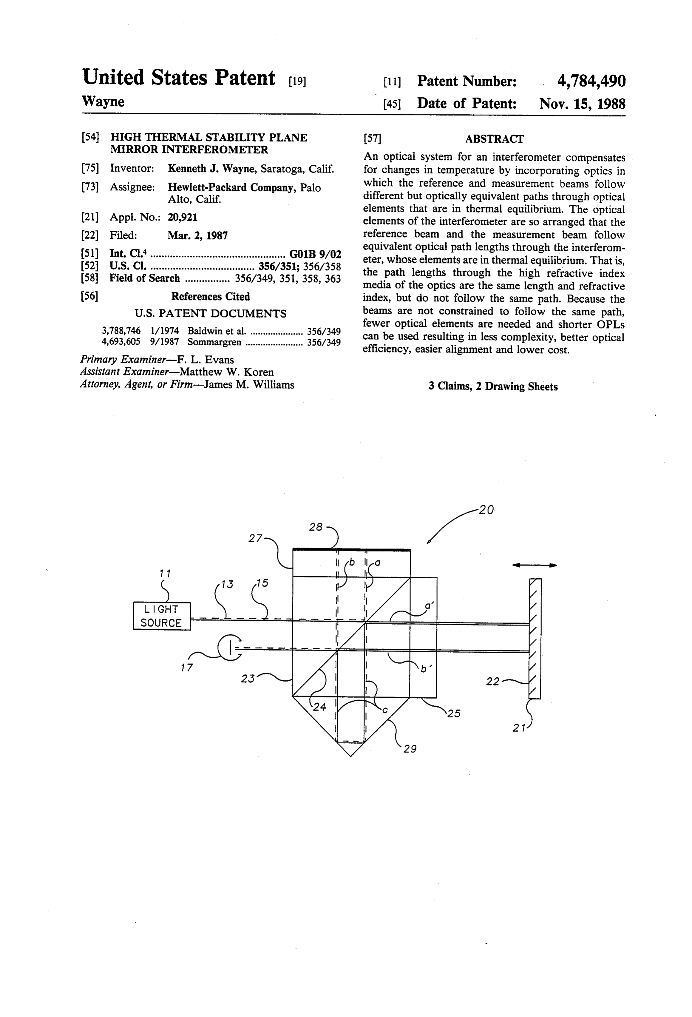
United States Patent (19) 11 Patent Number: 4,784,490 Wayne (45) Date of Patent: Nov. 15, 1988 (54) HIGH THERMAL STABILITY PLANE (57) ABSTRACT
MIRROR INTERFEROMETER
An optical system for an interferometer compensates 75 Inventor: Kenneth J. Wayne, Saratoga, Calif. for changes in temperature by incorporating optics in 73 Assignee: Hewlett-Packard Company, Palo which the reference and measurement beams follow Alto, Calif. different but optically equivalent paths through optical elements that are in thermal equilibrium. The optical (21) Appl. No.: 20,921 elements of the interferometer are so arranged that the (22 Filed: Mar. 2, 1987 reference beam and the measurement beam follow 51) Int. Cl.'................................................ G01B 9/02 equivalent optical path lengths through the interferom 52 U.S. Cl. ..................................... 356/351; 356/358 eter, whose elements are in thermal equilibrium. That is, 58 Field of Search ................ 356/349, 351, 358, 363 the path lengths through the high refractive index media of the optics are the same length and refractive 56) References Cited index, but do not follow the same path. Because the
3,788,746 1/1974 Baldwin et al. ..................... 356/349 fewer optical elements are needed and shorter OPLs 4,693,605 9/1987 Sommargren ....................... 356/349 can be used resulting in less complexity, better optical efficiency, easier alignment and lower cost.
Primary Examiner-F. L. Evans
Assistant Examiner-Matthew W. Koren
Attorney, Agent, or Firm-James M. Williams 3 Claims, 2 Drawing Sheets
Page 2
Drawing sheet — no readable text.
Page 3
Drawing sheet — no readable text.
Page 4
ing in less complexity, better optical efficiency, easier
HIGH THERMAL STABILITY PLANE MIRROR alignment and lower cost.
INTERFEROMETER
BRIEF DESCRIPTION OF THE DRAWINGS
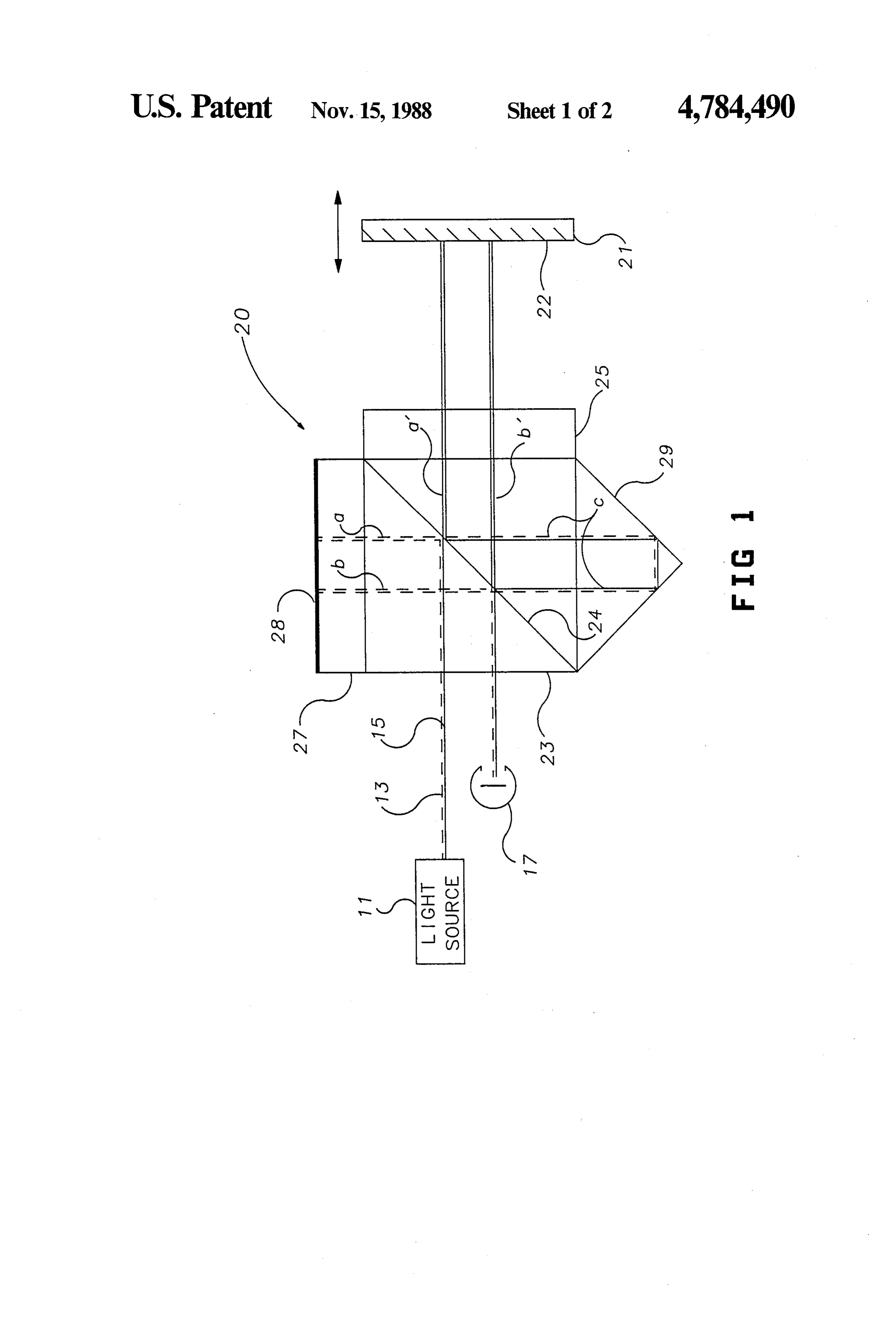
BACKGROUND AND SUMMARY OF THE 5 FIG. 1 is a schematic representation of an interferom INVENTION eter constructed in accordance with the preferred em An interferometer measures the change in distance bodiment of the invention, showing the paths of the reference and measurement beams.
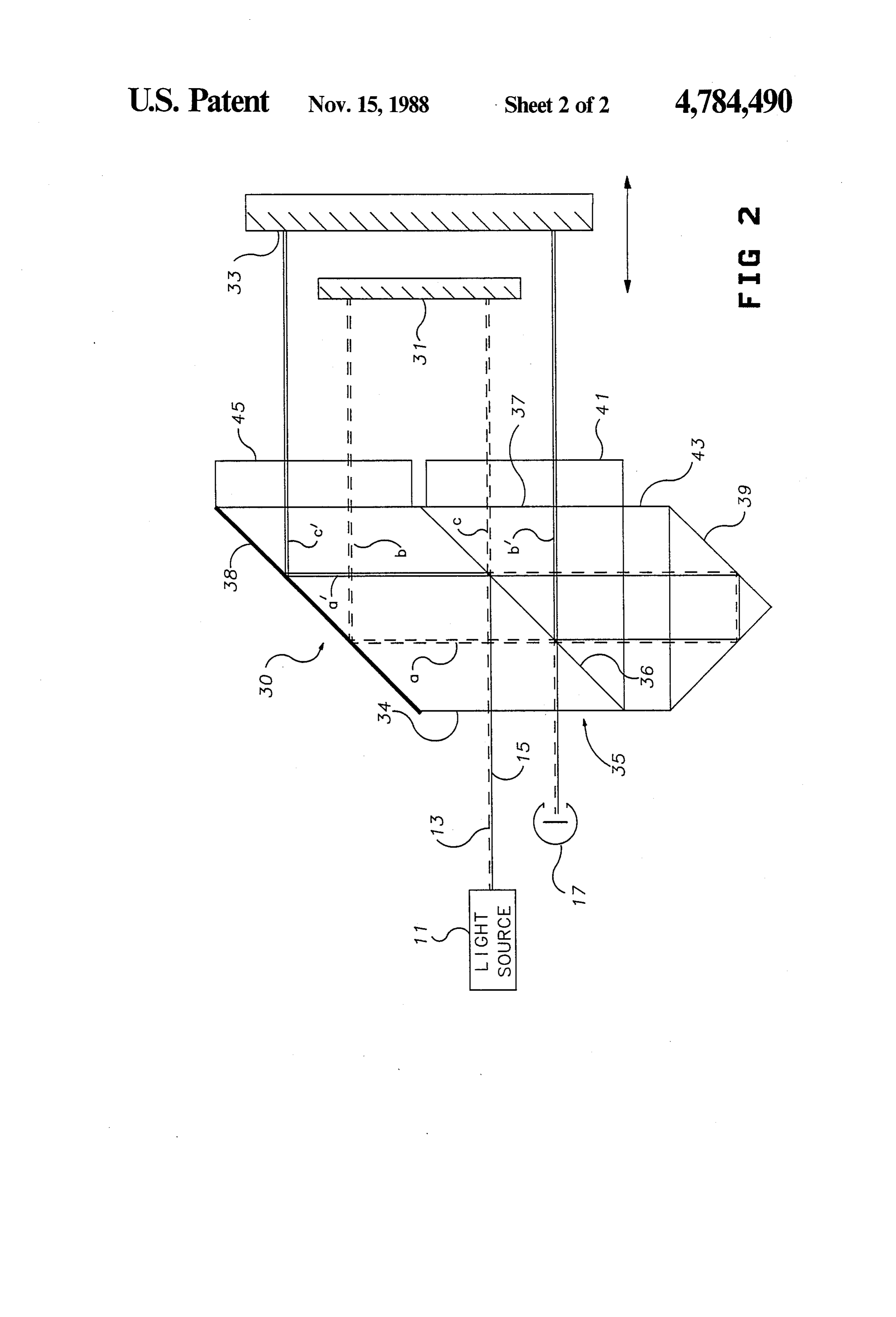
between a reference point and a movable point by mea suring the change in optical path length between the 10 eterFIG. 2 is a schematic representation of an interferom constructed in accordance with an alternative em two points. The change in the optical path length is measured by counting the number of fringes in an inter bodiment of the invention, showing the paths of the reference and measurement beams.
ference pattern caused by a measurement beam re flected from the movable point and a reference beam DETALED DESCRIPTION OF THE that follows a fixed path. 15 INVENTION The optical path length (OPL) is the product of the The preferred embodiment of the invention is a plane length of the beam's path and the refractive index of the mirror interferometer shown in FIG.1. The interferom medium through which the beam passes. Generally, the eter uses a light source 11 to produce a reference beam OPL is made up of a number of segments through air, 13 and a measurement beam 15. Light source 11 is pref which has a low refractive index, and a number of seg 20 erably a two-frequency laser producing a reference ments through glass, or some other medium of high beam 13 of frequency flinearly polarized in the plane refractive index. of the drawing and a measurement beam of frequency If the OPL changes due to the effects of a change in f2 linearly polarized perpendicular to the plane of the temperature on the refractive index of the optical ele drawing. The reference beam 13 and the measurement ments of the measuring instrument, the instrument will 25 beam 15 are directed to the optical assembly 20 of the register an erroneous distance change, just as if the interferometer, which reflects reference beam 13 back distance to be measured had changed. to detector 17 and transmits measurement beam 15 to a Early efforts to eliminate thermally induced errors movable measurement mirror 21. The mirror surface 22 were directed to the largest source of error, the me of movable mirror 21 reflects the measurement beam chanical supports for the optics. To compensate for 30 back to optical assembly 20 and then back to detector temperature variations, the supports were arranged so 17. Detector 17 uses a mixing polarizer to mix the two the change in position of the optical components in the beams and a photodetector to detect the fringes of the reference beam path was the same as the change for the resulting interference pattern.
components in the measurement beam path. According to the teachings of the invention, the opti Recently, interferometer instruments have been used 35 cal elements of optical assembly 20 are so arranged that in applications demanding increased measurement accu the reference beam 13 and the measurement beam 15 racy, for example wafer steppers for large scale inte follow equivalent optical path lengths through the opti grated circuits. This has led to a need to further com cal assembly 20, whose elements are in thermal equilib pensate for thermally induced errors. rium. Optical assembly 20 comprises a polarizing beam One proposed solution, is described in co-pending splitter 23 with a beam splitting surface 24 at a 45 degree U.S. application Ser No. 604,702, "Minimum Deadpath angle to the incident light beams, quarter wave plates 25 Interferometer and Dilatometer', filed Apr. 27, 1984 and 27 and aoncube corner 29, Quarter wave plate 25 is now U.S. Pat. No. 4,711,574 and assigned in common transparent both surfaces while quarter wave plate with this application. The device disclosed incorporates 45 27 has a high reflectance coating on one of its surfaces. interferometer optics with a common path for the refer and Quarter wave plates 25 and 27 have the same thickness ence and measurement beams. With the beams follow are made of the same material. Quarter wave plates ing the same path through the optics, changes in either 25 and 27 effectively rotate the plane of polarization of the refractive index or the dimensions of the optical quarterthe beams by 90 degrees each time the beams traverse a elements affect the OPL of both beams equally. This referencewave plate twice. Thus, the elements in the path of optical assembly 20 are of the same technique is particularly suitable for differential inter 50 material and size as their counterparts in the measure ferometers. However, it requires complex optics, which lower the optical efficiency of the instrument and are ment, path.
The path of reference beam 13 is reflected by beam relatively expensive.
An object of this invention is to provide a high ther 55 splitting changes surface 24 to quarter wave plate 27 which its polarization state. Then beam 13 passes mal stability interferometer that is relatively low cost, through the polarizing beam splitter 23 is reflected by has high optical efficiency and less complex optics, and cube corner 29 back through polarizing beam splitter 23 is easy to align and use. again to quarter wave plate 27 which again changes it The preferred embodiment of the present invention compensates for changes in temperature by incorporat polarization state. Next, beam 13 is reflected by beam splitting surface 24 on a path parallel to its original path ing optics in which the reference and measurement towards detector 17.
beams follow different but optically equivalent paths through optical elements that are in thermal equilib to Measurement beam 15, being polarized perpendicular reference beam 13, passes through beam splitting rium. That is, the path lengths through the high refrac surface 24 and through quarter wave plate 25 to mov tive index medium of the optics are the same length, but 65 able mirror 21 which reflects it back toward optical do not follow the same path. Because the beams are not assembly 20, again through quarter wave plate 25. This constrained to follow the same path, fewer optical ele time beam 15 is reflected by beam splitting surface 24 ments are needed and shorter OPLs can be used result toward cube corner 29 which returns splitting surface
Page 5
24 which directs measurement beam 15 back through through quarter wave plate 43 to cube corner 39, back quarter wave plate 25 to moveable measurement mirror through quarter wave plate 43 again with changed po 21 and then back through quarter wave plate 25. With larization state to surface 36 which reflects beam 15 the polarization state changed one more time, measure through quarter wave plate 41 to movable measurement ment beam 15 passes through beam splitting surface 24 mirror 33, then back through quarter wave plate 41, to detector 17. where finally with its polarization state changed again, It can be seen from an examination of FIG. 1 that the measurement beam 15 passes through surface 36 to where reference beam 13 and measurement beam 15 do detector 7.
not follow a common path, their path lengths through An inspection of the paths of reference beam 13 and the elements of optical assembly 20 are equivalent. In 10 measurement beam 5 in FIG. 2 reveals that where the particular, path a of reference beam 13 through the beams follow paths that are not common, their lengths beam splitter and quarter wave plate 27 is the same are equivalent. Thus, paths a, b and c of reference beam length as path a' of measurement beam 15 through the 13 have the same length as paths a, b' and c' of measure beam splitter and quarter wave plate 25. Similarly, path ment beam 15.
b of reference beam 13 is the same length as path b' of 15 I claim:
measurement beam 15. And path c from beam splitter 1. An interferometer having high thermal stability, surface 24 to cube corner 29 and return is common to comprising:
both reference beam 13 and measurement beam 15. light source means for producing a coherent light Thus, if the temperature of optical assembly 20 changes beam;
affecting the dimensions and the refractive index of the a light detector;
optical elements, the optical pathlengths of reference beam splitter means for separating the coherent light beam 13 and measurement beam 15 will be equally af. beam into a measurement beam and a reference fected if the elements of optical assembly 20 remain in beam;
thermal equilibrium. reflecting means, having substantially no optical path An alternative embodiment showing an application of 25 length, mounted on a movable measurement plane; the invention to differential measurements is shown in and
FIG. 2. Here the optics are adapted to allow the refer optical means having optical elements in thermal ence beam to be directed to a reference mirror 31 lo contact and in thermal equilibrium with the beam cated close to the movable mirror 33. This minimizes splitter, for cooperating with the beam splitter the "dead path' difference between the measurement 30 means to direct the reference beam along a refer beam and the reference beam further compensating for ence path to said detector, and to direct the mea thermally induced errors in the air path between the surement beam along a measurement path to said optical assembly and the movable mirror 33. detector, said measurement path including the In the embodiment of FIG. 2, the optical assembly 30 round trip distance to the reflecting means on the includes a polarizing beam splitter 35, which is a com 35 movable measurement plane; and pound prism comprising a porro prism 37 having a wherein the reference path passes through different triangular cross section, with a polarizing beam splitter optical elements than the measurement path, but surface 36 at a 45 degree angle to the incident beams, the reference path and the measurement path have connected to a parallelogram prism 34. substantially the same optical path length through Beam splitter 35 has a mirrored surface 38 which is said optical means and pass through optical ele parallel to beam splitting surface 36. Optical assembly ments of substantially the same refractive index, so 30 also includes cube corner 39 and quarter wave plates that the thermally induced changes in the optical 41, 43 and 45. Transparent quarter wave plates 41, 43 path length of the reference path and the optical and 45 have the same thickness and are made of the path length of the measurement path through the same material. 45 beam splitter and the optical means compensate Reference beam 13 is directed to beam splitter 35 one another.
where on its first pass, it passes through beam splitting 2. The interferometer of claim 1 wherein: surface 36 out through quarter wave plate 41 to refer the coherent light beam comprises a plane polarized ence mirror 31 where it is reflected back towards the reference component and a measurement compo beam splitter 35 again through quarter wave plate 41. 50 nent plane polarized perpendicular to the reference With changed polarization state, beam 13 is now re component;
flected by surface 36 down through quarter wave plate the beam splitter has a square cross section with a first 43 to cube corner 39 which reflects it back through surface through which the light beams enter from quarter wave plate 43 again with changed polarization the light source means, a second surface opposite state. Beam 13 now passes through surface 36 to mir 55 the first surface, third and fourth surfaces adjacent rored surface 38 of beam splitter 35 which directs it the first surface, and with a plane polarizing beam through quarter wave plate 45 to reference mirror 31 splitter surface diagonal to the first surface, and the back through quarter wave plate 45 to surface 38 which optical means comprises a transparent quarter directs the beam back down towards surface 36 where wave plate mounted on the second surface, a cube it is reflected to detector 17. 60 corner mounted on the third surface, and a reflec Measurement beam 15, polarized perpendicular to tive quarter wave plate mounted on the fourth beam 13, is reflected by surface 36 on its first pass, surface;
towards mirrored surface 38 which directs the beam the reference path passes sequentially through the through quarter wave plate 45 to movable measurement beam splitter, twice through the reflective quarter mirror 33, back through quarter wave plate 45 to mir 65 wave plate, once through the beam splitter, the rored surface 38. With changed polarization state as a cube corner, the beam splitter, twice through the result of passing through the quarter wave plate, the reflective quarter wave plate, once through the beam 15 is directed down and passes through surface 36, beam splitter, and to the detector; and
Page 6
the measurement path passes sequentially through the ter wave plate mounted on the altitude surface of beam splitter, the transparent quarter wave plate, the porro prism, a third transparent quarter wave to the reflecting means, through the transparent plate mounted on the third surface of the parallelo quarter wave plate, the beam splitter, the cube gram prism, and a reflective coating on the fourth corner, the beam splitter, the transparent quarter surface of the parallelogram prism; wave plate, to the reflecting means, through the the interferometer further comprising a fixed reflect transparent quarter wave plate, the beam splitter, ing means, having substantially no optical path and to the detector. length, mounted near the measurement plane; and 3. The interferometer of claim 1 wherein: the reference path passes sequentially through the the coherent light beam comprises a plane polarized O beam splitter, the second quarter wave plate, to the reference component and a measurement compo fixed reflecting means, through the second quarter nent plane polarized perpendicular to the reference wave plate, the beam splitter, the first quarter wave component; plate, the cube corner, the beam splitter, to the the beam splitter is a compound prism comprising a reflective coating, through the third quarter wave porro prism having altitude, base and hypotenuse 15 plate, to the fixed reflecting means, through the surfaces, with a polarizing beam splitter on its hy third quarter wave plate, the beam splitter, and to potenuse surface, connected to a parallelogram the detector; and prism with a first surface parallel to the altitude the measurement path passes sequentially through the surface of the porro prism, through which the light beam splitter, to the reflective coating, through the beams enter from the light source means, a second 20 third quarter wave plate, to the reflecting means on surface adjacent the first surface and connected to the measurement plane, through the third quarter the hypotenuse surface of the porro prism, a third wave plate, to the reflective coating, through the surface parallel to the first surface, and a fourth beam splitter, the first quarter wave plate, the cube surface parallel to the second surface; the optical corner, the beam splitter, the second quarter wave means comprises a first transparent quarter wave 25 plate, to the reflecting means on the measurement plate mounted on the base surface of the porro plane, through the second quarter wave plate, the prism, a cube corner mounted on the first transpar beam splitter, and tok the detector. ent quarter wave plate, a second transparent quar k it is k
Provenance
- Collection
- Cited prior art
- Original PDF
- patentimages.storage.googleapis.com →
- Filed
- 1987-03-02
- Pages
- 6
- Method
- pdftotext (the PDF's own text layer) + pdftoppm 300dpi page scans
- Source
- Google Patents bibliographic record
- Granted
- 1988-11-15
- Inventors
- Kenneth J. Wayne; Hewlett Packard Co
- Transcribed from
- patentimages.storage.googleapis.com →