patent · US476983
Pyromagnetic generator
14 June 1892
Page 1
Drawing sheet — no readable text.
Page 2
UNITED STATES PATENT OFFICE.
THOMAS A. EDISON, OF LLEWELLYN PARK, NEW JERSEY.
PYRO MAGNET C G ENERATOR.
SPECIFICATION forming part of Letters Patent No. 476,983, dated June 14, 1892. Application filed June 3, 1887. Serial No. 241,099, (No model.)
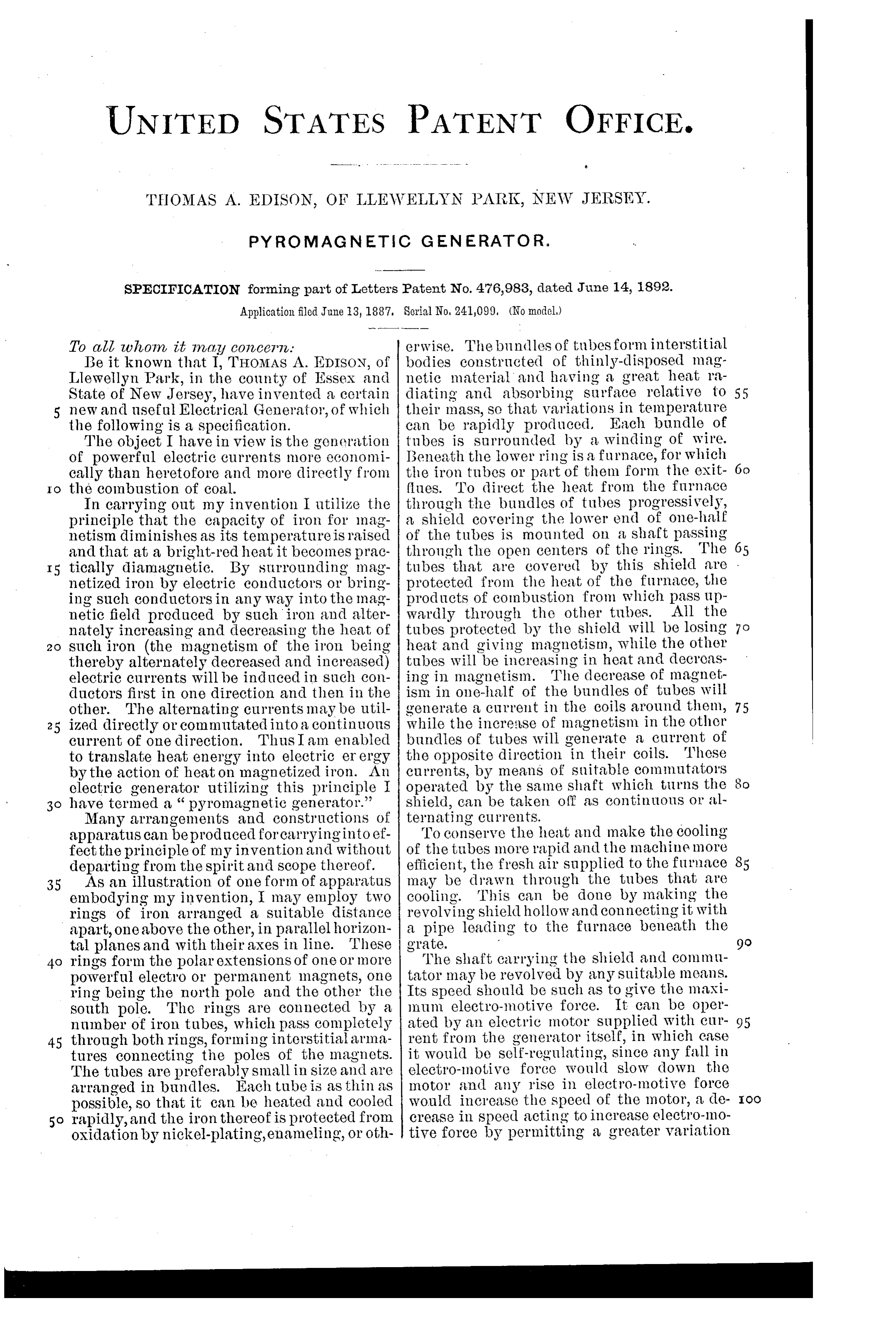
To all, whom, it may conce7 7. erwise. The bundles of tubes form interstitial Be it known that I, THOMAs A. EDISON, of bodies constructed of thinly-disposed mag Llewellyn Park, in the county of Essex and netic material and having a great heat ra State of New Jersey, have invented a certain diating and absorbing surface relative to 55 5 new and useful Electrical Generator, of which their mass, so that variations in temperature the following is a specification. can be rapidly produced. Each bundle of The object I have in view is the generation tubes is surrounded by a winding of wire. of powerful electric currents more economi IBeneath the lower ring is a furnace, for which cally than heretofore and more directly from the iron tubes or part of them form the exit- 6o ?lues. To direct the heat from the furnace
Io the combustion of coal.
In carrying out my invention I utilize the through the bundles of tubes progressively, principle that the capacity of iron for mag a shield covering the lower end of one-half netism diminishes as its temperature is raised of the tubes is mounted on a shaft passing and that at a bright-red heat it becomes prac through the open centers of the rings. The 65 I5 tically diamagnetic. By surrounding mag tubes that are covered by this shield are netized iron by electric conductors or bring protected from the heat of the furnace, the ing such conductors in any way into the mag products of combustion from which pass up netic field produced by such iron and alter wardly through the other tubes. All the nately increasing and decreasing the heat of tubes protected by the shield will be losing 7 O 2O such iron (the magnetism of the iron being heat and giving magnetism, while the other thereby alternately decreased and increased) tubes will be increasing in heat and decreas electric currents will be induced in such con ing in magnetism. The decrease of magnet ductors first in one direction and then in the ism in one-half of the bundles of tubes will other. The alternating currents may be util generate a current in the coils around them, 75 25 ized directly or commutated into a continuous while the increase of magnetism in the other Current of one direction. Thus I am enabled bundles of tubes will generate a current of to translate heat energy into electric er ergy the opposite direction in their coils. These by the action of heat on magnetized iron. An currents, by means of suitable commutator's electric generator utilizing this principle I operated by the same shaft which turns the 8o have termed a “pyromagnetic generator.’ shield, can be taken off as continuous or al Many arrangements and constructions of ternating currents.
apparatus can be produced for carrying into ef To conserve the heat and make the cooling fect the principle of my invention and without of the tubes more rapid and the machine more departing from the spirit and scope thereof. efficient, the fresh air supplied to the furnace 85 35 As an illustration of one form of apparatus may be drawn through the tubes that are embodying my invention, I may employ two cooling. This can be done by making the rings of iron arranged a suitable distance revolving shield hollow and connecting it with apart, one above the other, in parallel horizon a pipe leading to the furnace beneath the tal planes and with their axes in line. These grate. - rings form the polar extensions of one or more The shaft carrying the shield and commu powerful electro or permanent magnets, one tator may be revolved by any suitable means. ring being the north pole and the other the Its speed should be such as to give the maxi south pole. The rings are connected by a mum electro-motive force. It can be oper number of iron tubes, which pass completely ated by an electric motor supplied with cur- 95 45 through both rings, forming interstitial arma rent from the generator itself, in which case tures connecting the poles of the magnets. it would be self-regulating, since any fall in The tubes are preferably small in size and are electro-inotive force would slow down the arranged in bundles. Each tube is as thin as motor and any rise in electro-motive force possible, so that it can be heated and cooled would increase the speed of the motor, a de- roo 5o rapidly, and the iron thereof is protected from crease in speed acting to increase electro-mo oxidation by nickel-plating, enameling, or oth tive force by permitting a greater variation
Page 3
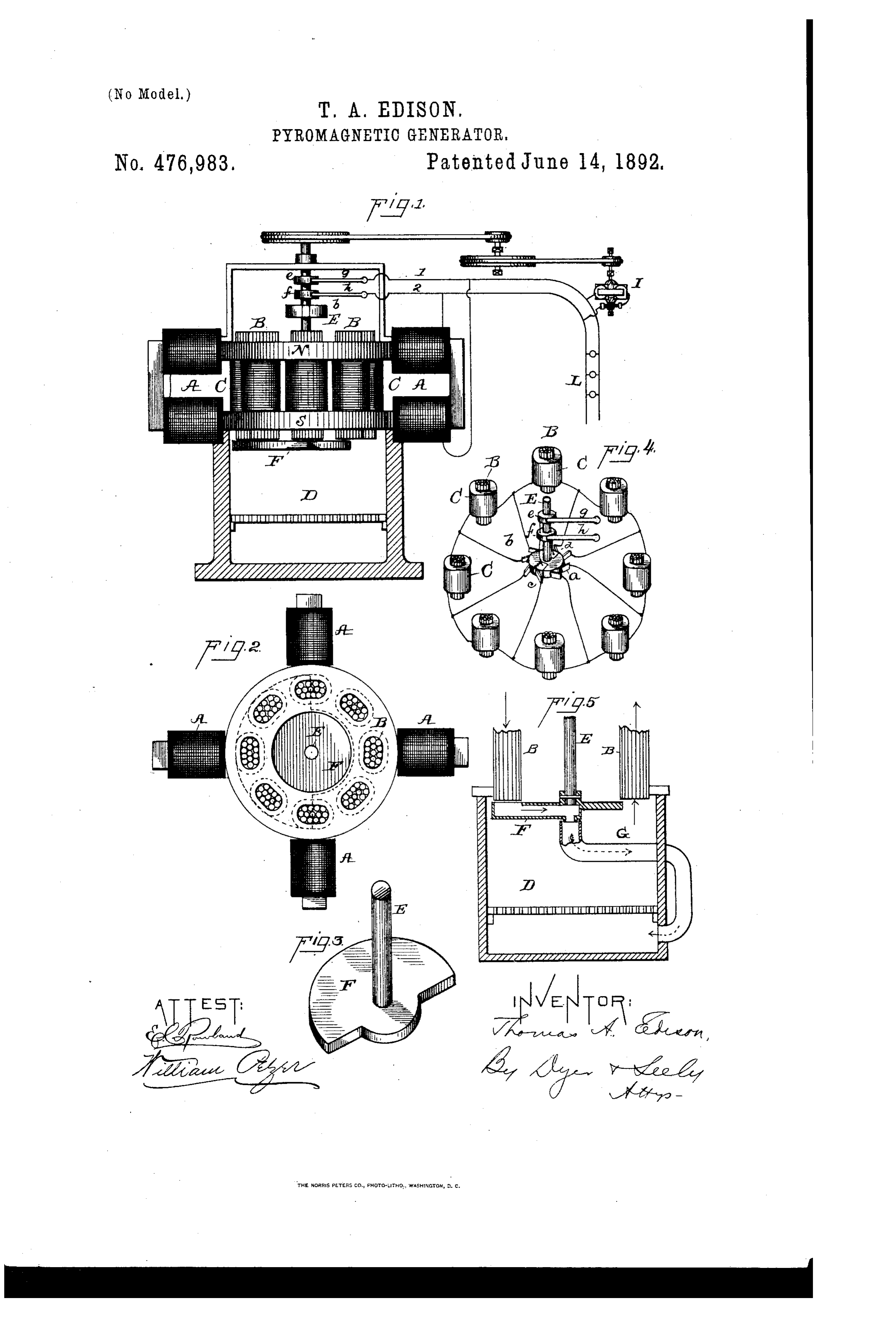
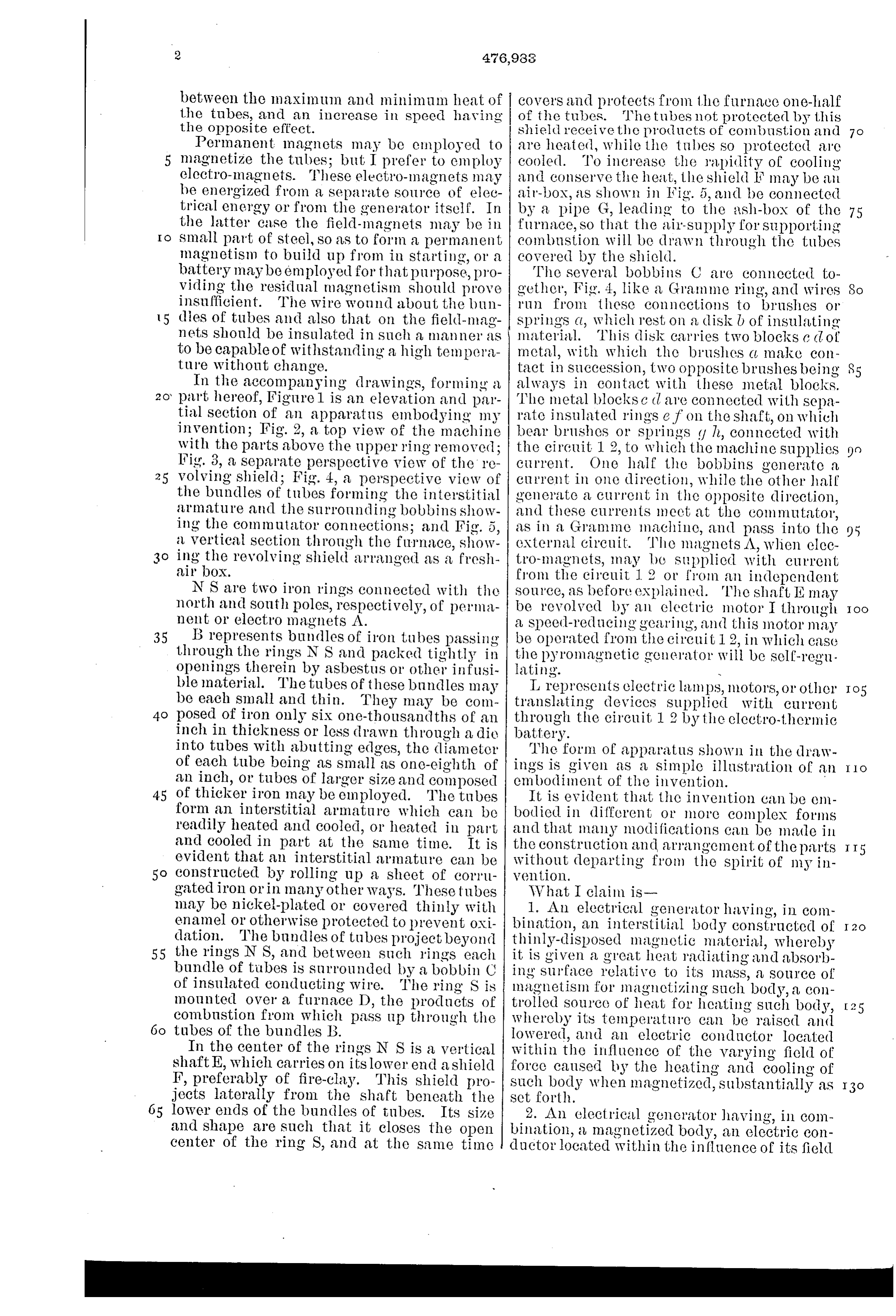
between the maximum and minimum heat of covers and protects from the furnace one-half the tubes, and an increase in speed having of the tubes. The tubes not protected by this the opposite effect. shield receive the products of combustion and 7 O Permanent magnets may be employed to are heated, while the tubes so protected are magnetize the tubes; but I prefer to employ cooled. To increase the rapidlity of cooling electro-magnets. These electro-magnets may and conserve the heat, the shield F may be all be energized from a separate source of elec air-box, as shown in Fig. 5, and be connected trical energy or from the generator itself. In by a pipe G, leading to the ash-box of the 75 the latter case the field-magnets may be in furnace, so that the air-supply for Supporting O small part of steel, so as to form a permanent combustion will be drawn through the tubes magnetism to build up from in starting, or a covered by the shield.
battery may be employed for that purpose, pro The several bobbins C are connected to viding the residual magnetism should prove gether, Fig. 4, like a Gramme ring, and wires So insufficient. The wire wound about the l) un run from these connections to brushes or l 5 dies of tubes and also that on the field-mag springs (l, which rest on a disk l) of insulating nets should be insulated in such a manner as material. This disk carries two blocks C (lof to be capable of withstanding a high tempera metal, with which the brushes (t, make con ture without change. tact in succession, two opposite brushes being In the accompanying drawings, forming a always in contact with these metal blocks. part hereof, Figurel is an elevation and par The metal blocks c clare connected with sepa tial Section of an apparatus embodying my rate insulated rings e. f on the shaft, on which invention; Fig. 2, a top view of the machine bear brushes or springs (1 h, connected with with the parts above the upper ring removed; the circuit 12, to which the machine Supplies Fig. 3, a separate perspective view of the re current. One half the bobbins generate a 25 volving shield; Fig. 4, a perspective view of current in one direction, while the other half the bundles of tubes forming the interstitial generate a current in the opposite direction, armature and the surrounding bobbins show and these currents meet at the commutator, ing the commutator connections; and Fig. 5, as in a Gramme machine, and pass into the 95 a vertical section through the furnace, show (external circuit. The magnets A, when elec ing the revolving shield arranged as a fresh tro-magnets, may be supplied with current air box. from the circuit 1 2 or from an independent N S are two iron rings connected with the source, as before explained. The shaft E may north and South poles, respectively, of perma be revolved by an electric motor I through OO nent or electro magnets A. a speed-reducing gearing, and this motor may 35 B represents bundles of iron tubes passing be operated from the circuit 12, in which case through the rings N S and packed tightly in the pyromagnetic generator will be self-regu. openings therein by asbestus or other infusi lating. - ble material. The tubes of these bundles may L represents electric lamps, motors, or other be each small and thin. They may be com translating devices supplied with current posed of iron only six one-thousandths of an through the circuit 12 by the electro-thermic inch in thickness or less drawn through a die battery.
into tubes with abutting edges, the diameter The form of apparatus shown in the draw of each tube being as small as one-eighth of ings is given as a simple illustration of an II O an inch, or tubes of larger size and composed embodiment of the invention. 45 of thicker iron may be employed. The tubes It is evident that the invention can be em form an interstitial armature which can be bodied in different or more complex forms readily heated and cooled, or heated in part and that mally modifications can be made in and cooled in part at the same time. It is the construction and arrangement of the parts I I5 evident that an interstitial armature can be without departing from the spirit of my in constructed by rolling up a sheet of corru vention.
gated iron or in many other ways. These tubes What I clain is may be nickel-plated or covered thinly with 1. An electrical generator having, in com enamel or otherwise protected to prevent oxi bination, an interstitial body constructed of dation. The bundles of tubes project beyond thinly-disposed magnetic material, whereby 55 the rings N S, and between such lings each it is given a great heat radiating and absorb bundle of tubes is surrounded by a bobbin C ing surface relative to its mass, a source of of insulated conducting wire. The ring S is magnetism for magnetizing such body, a con mounted over a furnace D, the products of trolled source of heat for heating such body, combustion from which pass up through the whereby its temperature can be raised and I 25 tubes of the bundles B. lowered, and an electric conductor located In the center of the rings N S is a vertical within the influence of the varying field of shaft E, which carries on its lower end a shield force caused by the heating and cooling of F, preferably of fire-clay. This shield pro such body when magnetized, substantially as I 30 jects laterally from the shaft beneath the set forth.
lower ends of the bundles of tubes. Its size 2. An electrical generator having, in com and shape are such that it closes the open bination, a magnetized body, an electric con center of the ring S, and at the same time ductor located Within the influence of its field
Page 4
of force, a controlled source of heat for heat heat to and cutting it off from such magnet ing such body, whereby its temperature can ized bodies in succession, whereby the tem be raised and lowered, and a commutator for perature of such bodies is progressively raised 7 O commutating the alternating current gener and lowered, and a cold-air channel controlled ated in said electric conductor into a straight by said director or shield and connected there current, substantially as set forth. by with the magnetized bodies as they are cut 3. An electrical generator having, in com off from the source of heat, substantially as bination, an interstitial body constructed of Set forth. 75 thinly-disposed magnetic material, whereby 9. An electrical generator having, in Com O it is given a great heat radiating and absorb bination, a series of magnetized interstitial ing Surface relative to its mass, a source of bodies constructed of thinly-disposed mag magnetism for magnetizing such body, a con netic material, so as to have a great heat ra trolled Source of heat for heating such body, diating and absorbing surface relative to their whereby its temperature can be raised and mass, electric conductors located within the 15 lowered, an electric conductor located within influence of the fields of force of such bodies, the influence of the varying field of force a source of heat, and a heat director or shield caused by the heating and cooling of such directing the heat to and cutting it off from body when magnetized, and a commutator for such magnetized bodies in succession, where commutating the alternating current gener by the temperature of such bodies is progress ated in said electric conductor into a straight ively raised and lowered, substantially as set Clil'rent, Substantially as set forth. forth.
4. An electrical generator having, in com 10. In an electrical generator, the combina bination, a magnetized body, an electric con tion, with a magnet, of an interstitial body of ductor located within the influence of its field magnetic material placed in metallic connec of force, a Source of heat for heating such body, tion with both poles of the magnet and form and a moving director or shield alternately ing a keeper thereto, an electric conductor directing the heat to and cutting it off from wound around or upon such interstitial body, such magnetized body, substantially as set and a controlled source of heat, whereby the 95 forth. temperature of such interstitial body can be 3O 5. An electrical generator having, in com raised and lowered, substantially as set forth. bination, a magnetized body, an electric con 11. An electrical generator wherein are ductor located within the influence of its field combined two iron rings or plates connected of force, a source of heat for heating such body, by a number of interstitial bodies of magnetic OO a moving director or shield alternately direct material, one or more magnets magnetizing 35 ing the heat to and cutting it off from such such rings or plates and interstitial bodies, magnetized body, and a cold-air channel con conductors wound around such interstitial trolled by said director or shield and connected bodies, a furnace, and means for directing the thereby with said magnetized body when the heat from such furnace through such bundles heat is cut off therefrom, substantially as set of tubes progressively, substantially as set
6. An electrical generator having, in com 12. An electrical generator wherein are bination, a series of magnetized bodies, elec combined two iron rings or plates connected tric conductors located within the influence by a number of interstitial bodies of mag IO of the fields of force of such bodies, a source netic material, one or more magnets magnet 45 of heat, and a heat director or shield direct izing such rings or plates and interstitial ing the heat to and cutting it off from such bodies, conductors wound around such inter magnetized bodies in succession, whereby the stitial bodies, a furnace, and means for direct temperature of such bodies is progressively ing the heat from such furnace through such II5 raised and lowered, substantially as set forth. interstitial bodies progressively and for draw 7. An electrical generator having, in com ing fresh air to supply said furnace through bination, a series of magnetized bodies, elec the interstices of the other bodies, substan tric conductors located within the influence tially as set forth.
of the fields of force of such bodies, a source 13. An electrical generator wherein are 2C) of heat, a heat director or shield directing the combined two iron rings or plates connected 55 heat to and cutting it off from such magnet by a number of interstitial bodies of mag ized bodies in succession, whereby the tem netic material, one or more magnets magnet perature of such bodies is progressively raised izing such rings or plates and interstitial and lowered, and a commutator collecting the bodies, conductors wound around such inter I 25 currents from said several electric conductors stitial bodies, a furnace, and a moving shield and delivering them as a straight current to covering the open ends of such interstitial the translation - circuit, substantially as set bodies in succession and cutting them off forth. from the heat of the furnace, substantially as S. An electrical generator having, in com set, forth.
bination, a series of magnetized bodies, elec 14. An electrical generator wherein are tric conductors located within the influence combined two iron rings or plates connected of the fields of force of such bodies, a source by a number of interstitial bodies of mag of heat, a heat director or shield directing the netic material, one or more magnets magnet
Page 5
izing such rings or plates and interstitial tor supplied with current by said commutator bodies, conductors wound around such inter and operating both said commutator and said stitial bodies, a furnace, a moving shield cow directing means, substantially as set forth. 25 ering the open ends of such interstitial bodies 17. An electrical generator wherein are in succession, and a fresh-air duct connected combined two iron rings or plates connected with said shield for drawing fresh air through by a number of interstitial bodies of magnetic the tubes covered by the shield, substantially material, one or more magnets magnetizing as set forth. such rings or plates and interstitial bodies, 15. The combination, with the moving heat conductors wound around such interstitial directing shield of a pyromagnetic generator, bodies, a furnace, a moving shield covering of a motor moving such shield operated or the open ends of said interstitial bodies in suc controlled by the current from such generator, cession and cutting them off from the heat of whereby the generator is made self-regulat the furnace, and an electric motor operating 35 ing, substantially as set forth. said shield and supplied with current from 16. An electrical generator wherein are such conductors, substantially as set forth. combined a series of magnetized bodies, elec This specification signed and witnessed this tric conductors within the influence of the 24th day of May, 1887.
fields of force of such bodies, a source of heat, TIOS. A. EDISON. a moving director or shield for directing the heat to such bodies progressively, a moving Witnesses:
commutator for collecting the currents in WILLIAM PELZER, duced in said conductors, and an electric mo E. C. ROWLAND.
Provenance
- Collection
- Cited prior art
- Original PDF
- patentimages.storage.googleapis.com →
- Pages
- 5
- Method
- pdftotext (the PDF's own text layer) + pdftoppm 300dpi page scans
- Source
- Google Patents bibliographic record
- Granted
- 1892-06-14
- Transcribed from
- patentimages.storage.googleapis.com →