patent · US4676599
Micro-optical lens holder
30 June 1987
Page 1 — bibliographic record
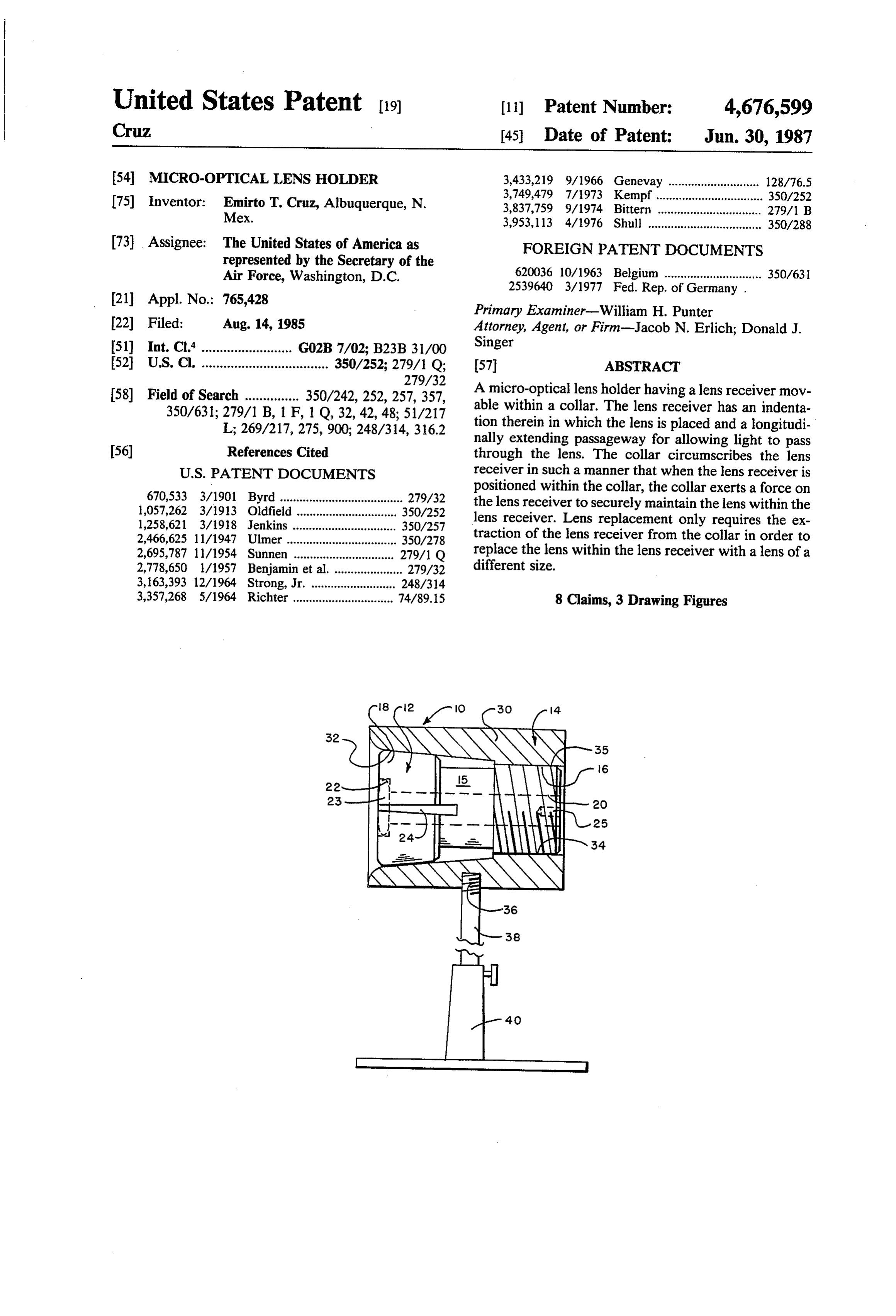
United States Patent (19) 11 Patent Number: 4,676,599 Cruz 45 Date of Patent: Jun. 30, 1987 54 MICRO-OPTICAL LENS HOLDER 3,433,219 9/1966 Genevay ............................ 128/76.5 75) Inventor: Emirto T. Cruz, Albuquerque, N. 3,749,479 7/1973 Kempf................................. 350/252 Mex. 3,837,759 9/1974 Bittern ................................ 279/1 B 3,953,113 4/1976 Shull ................................... 350/288 73 Assignee: The United States of America as FOREIGN PATENT DOCUMENTS represented by the Secretary of the
Air Force, Washington, D.C. 620036 10/1963 Belgium .............................. 350/631
Primary Examiner-William H. Punter 22 Filed: Aug. 14, 1985 Attorney, Agent, or Firm-Jacob N. Erlich; Donald J. 51) Int. Cl. ......................... G02B 7/02; B23B31/00 Singer 52 U.S.C. ................................... 350/252; 279/1 Q; 57 ABSTRACT
58) Field of Search ............... 350/242, 252,257,357, A micro-optical lens holder having a lens receiver mov 350/631; 279/1B, 1 F, 1 Q, 32, 42,48; 51/217 able within a collar. The lens receiver has an indenta L; 269/217, 275,900; 248/314, 316.2 tion therein in which the lens is placed and a longitudi nally extending passageway for allowing light to pass (56) References Cited through the lens. The collar circumscribes the lens receiver in such a manner that when the lens receiver is
670,533 3/1901 Byrd ....... ... 279/32 the lens receiver to securely maintain the lens within the 1,057,262 3/1913 Oldfield. 350/252 lens receiver. Lens replacement only requires the ex 1,258,621 3/1918 Jenkins ....... ... 350/257 traction of the lens receiver from the collar in order to 2,466,625 11/1947 Ulmer.................................. 350/278 2,695,787 11/1954 Sunnen ............... ... 279/1 Q replace the lens within the lens receiver with a lens of a 2,778,650 1/1957 Benjamin et al. ..................... 279/32 different size.
3,357,268 5/1964 Richter ............................... 74/89.15 8 Claims, 3 Drawing Figures
Page 2
Drawing sheet — no readable text.
Page 3
Drawing sheet — no readable text.
Page 4
the indentation which contains the lens therein com
MICRO-OPTICAL LENS HOLDER pletely through the threaded rear portion of the re
STATEMENT OF GOVERNMENT INTEREST
ceiver so as to allow a light beam to pass therethrough when the lens is in place. A pair of small openings situ
The invention described herein may be manufactured 5 ated at the rear of the lens receiver adjacent the and used by or for the Government for governmental threaded end enables a tool to be inserted therein in purposes without the payment of any royalty thereon. order to screw or unscrew the receiver into or from the collar, respectively.
BACKGROUND OF THE INVENTION The collar is made up of a cylindrically-shaped annu This invention relates generally to lenses, and, more 10 lar member having a tapered interior, with one end particularly, to a uniquely designed small optical lens portion thereof having internal threads capable of mat holder capable of easily permitting the replacement of ing with the external threads on the lens receiver. The the lens within the holder. tapered housing portion of the lens receiver conforms With the substantial use of optical systems requiring 15 to the interior taper of the collar such that when the lens miniaturized lenses or micro-optical lenses therein, it receiver is screwed into the collar and the receiver is has become increasingly necessary to provide a holder drawn rearward, the taper on the collar acts in a cam which enables such micro-optical lenses to be readily like fashion to deflect the slotted housing portion of the replaced therein. Many laboratory systems such as receiver against the lens situated within the opening those involving the use of lasers or microscopic work therein. In this manner the lens is securely held in place require as part of the system micro-optical lenses of 20 within the lens receiver.
approximately 7-8 mm in diameter. In addition, with the miniaturization of cameras and photographic equip necessary tois unscrew
When it desirable to replace the lens, it is merely ment it also becomes necessary to provide such small This action releases thethepressure lens receiver from the collar. on the housing portion lenses in cameras, microscopes and other related optical and enables the lens to be withdrawn from the lens
devices. Heretofore, most miniaturized lens systems indentation. By having a light passageway or aperture involved the use of lenses which were permanently contained within a cylindrical-type holder. It therefore pass through the entire length of the receiver the lens became necessary when the replacement of such a lens through operable may be with a light beam being passed there was desired that the entireholder of the lens be replaced cally manufactureddirection.
in either
The collar may be specifi be used with any type of with another holder having the appropriate lens also 30 permanently secured therein. Such a system created a optical system, or, if desired, the collar may be of a plain large expense in maintaining a tremendous inventory of external configuration and be adjustably mounted upon such lens/holder combinations. Furthermore, the stor an optical stand.
age space required for the numerous types of lens/- It is therefore an object of this invention to provide a holder combinations has been greatly increased with 35 holder for micro-optical lenses.
the increased requirement for a variety of lenses of It is another object of this invention to provide a different powers of magnification required in optical micro-optical lens holder in which the lens contained systems in use today. therein can be readily replaced by various other types of It is therefore highly desirable to provide for a lens lenses.
holder which is particularly suited to removably con It is a further object of this invention to provide a tain a lens therein, and, in particular, a micro-optical micro-optical lens holder which finds utility when uti lens. lized in a number of different types of optical systems.
SUMMARY OF THE INVENTION
It is still a further object of this invention to provide a micro-optical lens holder which is economical to pro
The present invention overcomes the problems en 45 duce and which utilizes conventional, currently avail countered in the past and as set forth in detail herein able components that lend themselves to standard mass above by providing a micro-optical lens holder which producing manufacturing techniques.
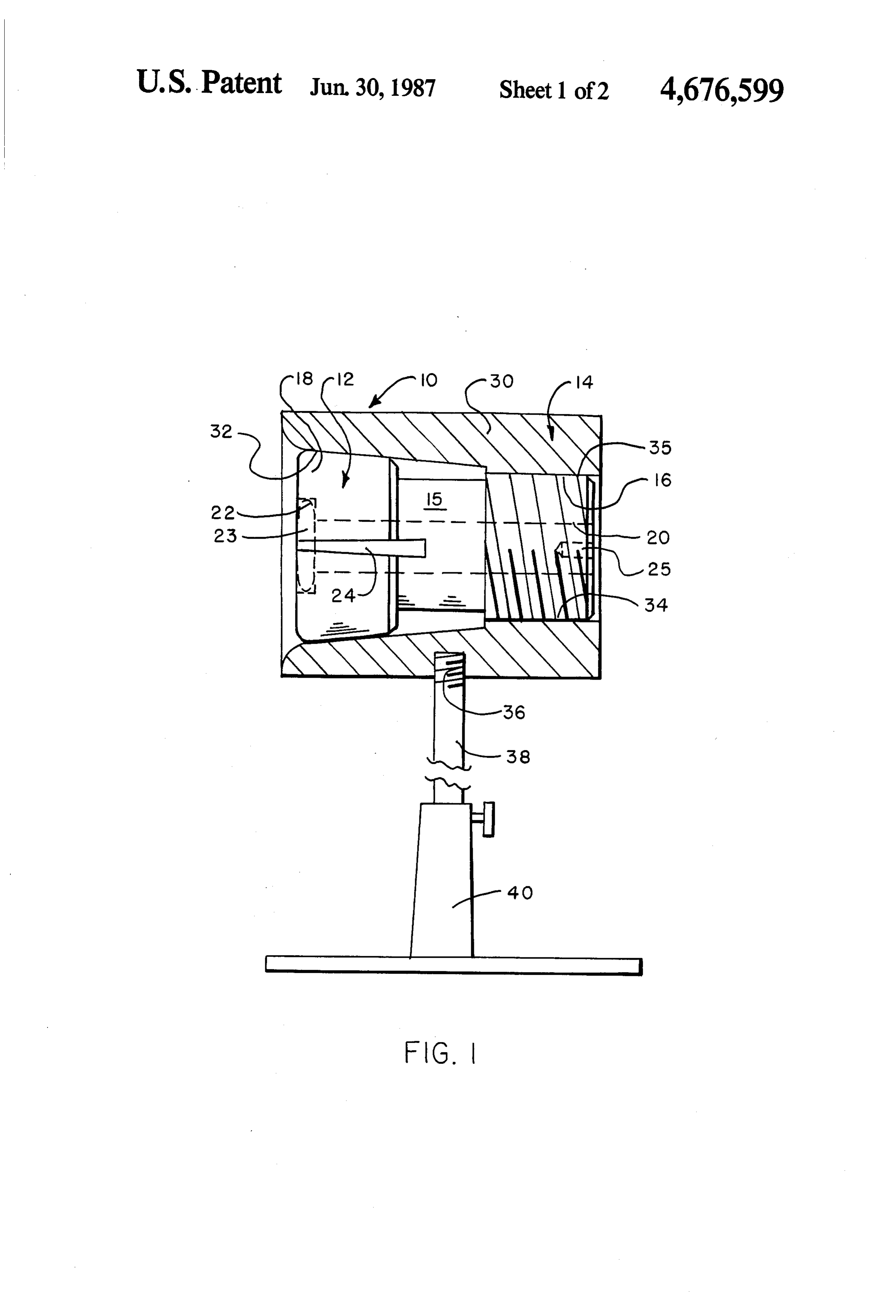
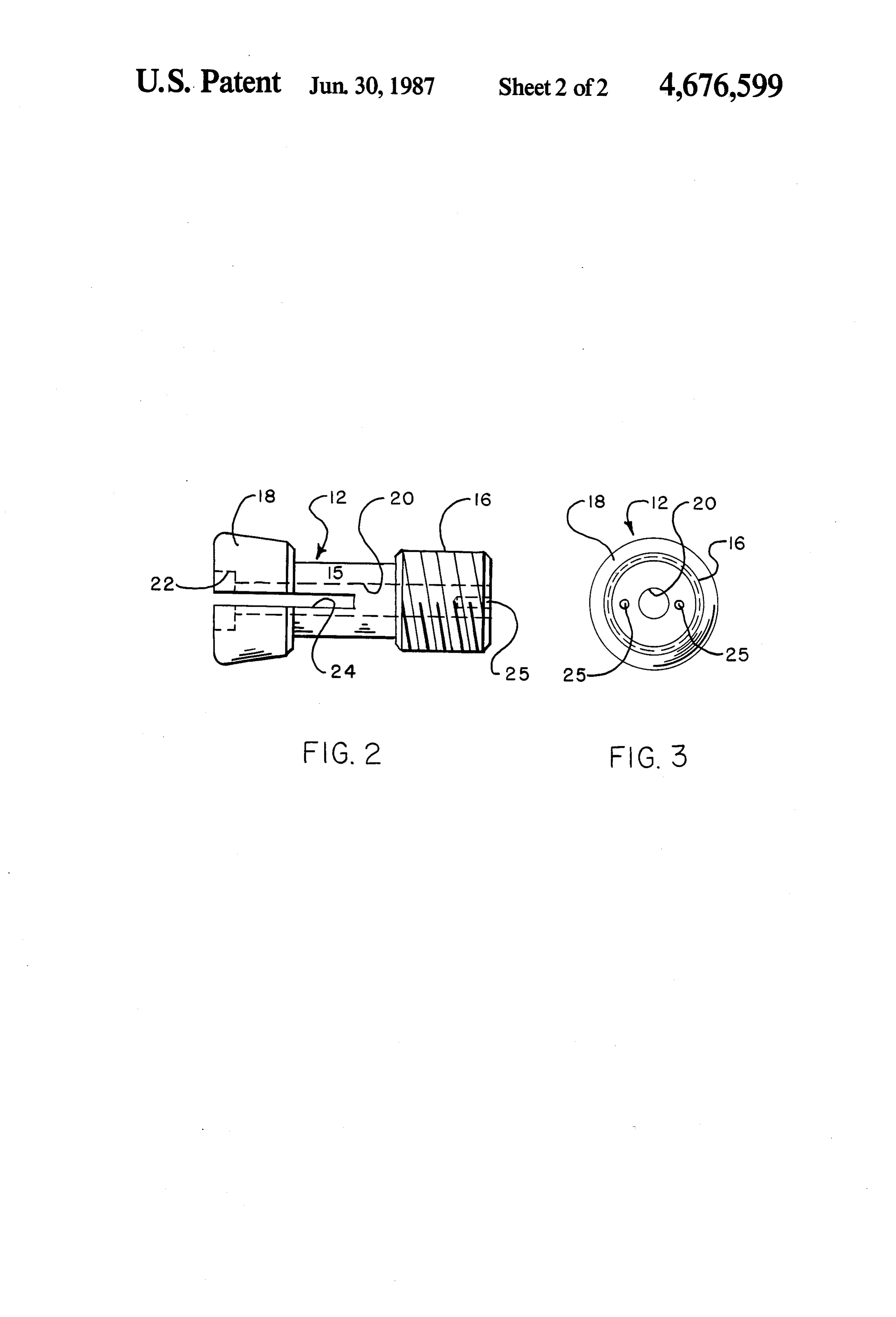
not only enables various lenses to be replaceable within For a better understanding of the present invention, the holder, but also enables high accuracy mounting of together with other and further objects thereof, refer the lens within an optical system. 50 ence is made to the following description, taken in con The lens holder of the present invention is made up of junction with the accompanying drawings and its scope two major components, a substantially cylindrically will be pointed out in the appended claims. shaped collar and a lens receiver. In addition, if so de BRIEF DESCRIPTION OF THE DRAWINGS sired, the lens collar may be mounted upon an adjust able stand for use within an optical system. More partic 55 FIG. 1 is a side elevational view showing the micro ularly, the lens receiver is designed of an elongated optical lens holder of the present invention partly in member being threaded at one end thereof and having a cross section;
tapered housing portion at the other end thereof. Situ FIG. 2 is a side elevational view of the lens receiver ated within the tapered housing portion is an indenta of the micro-optical lens holder of the present inven tion which can accommodate a lens therein which is tion; and preferably in the form of a micro-lens 7-8 mm in diame FIG. 3 is an end view of the lens receiver of the ter. A plurality of longitudinal, circumferentially micro-optical lens holder of the present invention. spaced apart slots are provided within the housing por DETAILED DESCRIPTION OF THE tion so as to enable the housing portion to have suffi cient deflection capability. Consequently, the lens can 65 PREFERRED EMBODIMENT be placed therein and securely held within the housing Reference is now made to FIG. 1 of the drawings in portion when the receiver is placed within the collar. In which the micro-optical lens holder 10 of this invention addition, a longitudinally extending aperture runs from is clearly illustrated in a partially cross sectioned view.
Page 5
As is evident from FIG. 1, lens holder 10 of the presentportion 18 to take place upon lens 23 in order to se invention is made up of two major components: (1) a curely hold lens 23 within indentation 22. In this man lens receiver 12 and (2) a collar 14 which operably ner lens 23 is aligned with the longitudinal passageway engages the lens receiver 12. More specifically, as 20 passing through receiver 12. If lens 23 is to be re shown in FIGS. 1-3 of the drawings, the lens receiver 5 placed, it is merely necessary to unscrew receiver 12 12 is made up of a rod-shaped member or body 15 hav from collar 14. As receiver 12 is withdrawn from collar ing external threads 16 at one end portion thereof and 14 housing portion 18 springs back to its original config an enlarged tapered lens housing portion 18 at the other uration and permits the release of lens 23 situated within end thereof. A centrally located opening or passageway indentation 22. In this manner a number of different 20 is formed along the longitudinal axis of receiver 12 to O sized lenses can be easily accommodated by receiver 12 allow the passage of light therethrough. In addition, a so that holder 10 may be utilized in a number of differ lens receiving indentation 22 is formed at the other end ent optical systems.
of housing 12 to accommodate any suitable sized lens Although any suitable tool may be used in conjunc 23. Although the exact dimensions of the lens 23 con tion with holder 10 in order to rotate receiver 12 with tained within the indentation 22 may vary within the 15 respect to collar 14 it is preferable that a two pronged scope of the present invention, it is preferable that such instrument be inserted within the appropriate openings a lens indentation accommodate micro-optical lenses of 25. Once in position, the instrument can easily rotate between 7-8 mm in diameter. receiver 12 within collar 14.
Also formed within the housing portion 18 of re Although the external configuration of the collar 14 ceiver 12 are a plurality of longitudinally extending 20 may vary in accordance with the use of lens holder 10, slots 24 (only one of which is shown in the drawings) spaced apart along the outer circumference of housing the exterior portion of collar 14 contains a threaded opening 36 therein which is used to threadably engage 18 so as to enable the housing portion 18 to have a small an adjustable rod 38 situated within a conventional degree of deflection when subjected to an external force optical stand 40. In this manner the micro-optical lens in a manner to be described in detail hereinbelow. The 25 holder 10 of the present invention can be readily utilized threaded portion 16 of body 15 of lens receiver 12 has a within any type of optical system in which it is desirable pair of small openings 25 situated therein to receive an to use a wide range of different sized optical lenses. apppropriate tool in order to rotate lens receiver 12 Although this invention has been described with with respect to collar 14 so to enable lens receiver 12 to reference be secured within collar 14. Although not limited to the stood thattothisa particular
following dimensions, lens receiver 12 is generally ap other embodiments withinis the invention also capable of further and spirit and scope of the proximately 1.5 inches in length with the housing por appended claims.
tion 18 thereof approximately 0.31 inches in length and I claim:
the threaded portion 16 approximately 0.5 inches in 1. A lens holder comprising: length. The largest external diameter of the tapered 35 (a) an elongated member, said elongated member housing portion of receiver 12 is approximately 0.62 having inches in diameter while the diameter of the threaded portion 16 is approximately 0.5 inches in diameter. an indentation in one end thereof for removably Reference is now made to collar 14 also shown in receiving a lens therein. FIG. 1 of the drawings. It is clearly illustrated in FIG. a longitudinally extending passageway there 1 that this collar 14 is made of a substantially cylindri through interconnected at one end thereof with cal, annular-shaped element 30 having a tapered interior said indentation, said passageway being in opti configuration. More specifically, although not limited cal alignment with said lens located within said to the following dimensions, one end 32 of collar 14 has indentation, an internal diameter of approximately 0.69 inches while 45 a plurality of longitudinally extending, circumfer the other end 34 has internal threads 35thereon and is of entially spaced apart slots adjacent said indenta an inner diameter of approximately 0.5 inches so as to tion, and matingly engage with the external threads 16 of body 15 a threaded exterior portion adjacent the other end of receiver 12. The tapered interior configuration of thereof; and collar 14 is designed so as to matingly engage with the 50 (b) means circumscribing said elongated member for tapered housing portion 18 of receiver 12. Upon inser maintaining said lens within said indentation, said tion of receiver 12 so that threaded portions 16 and 35 lens maintaining means having a tapered interior are in threadable engagement with each other, pressure opening therethrough, with one end thereof en is applied to housing portion 18 by the tapered interior gaaging said elongated member adjacent said slots, of collar 14 to create a deflection of housing portion 18. 55 and
This deflection securely holds lens 23 in place. It is the said lens maintaining means having a threaded longitudinal slots 24 located within housing portion 18 interior portion for matingly engaging said of receiver 12 which enables the deflection or spring threaded exterior portion of said elongated mem like action to be increased as receiver 12 is threaded into ber;
collar 4. whereby said lens may be easily replaced within said In use, any suitable lens 23 such as a mirco-optical lens holder with a different lens. lens falling within the range of approximately 7-8 mm 2. A lens holder as defined in claim 1 wherein said in diameter can be inserted within the indentation 22 elongated member has a pair of openings adjacent an within receiver 12. The receiver 12 is then threaded into end thereof for receiving a tool capable of rotating said the collar 14 in such a manner that the tapered interior 65 elongated member within said lens maintaining means. portion of collar 14 engages the tapered exterior portion 3. A lens holder as defined in claim 2 wherein said of housing 18 of receiver 12. Continued insertion of elongated member has a tapered housing portion en receiver 12 within collar 14 causes deflection of housing compassing said indentation, said tapered housing por
Page 6
tion matingly engaging said tapered interior of said lens allow deflection of said tapered portion of said maintaining means in a cam-like fashion. body to take place about said indentation; and 4. A lens holder as defined in claim 3 wherein said a collar, said collar being of substantially cylindrical lens maintaining means is in the form of a collar having configuration and having an internal passageway a threaded opening on an exterior wall thereof for oper therein, said internal passageway having a tapered ably engaging an optical stand. preselected internal diameter at one end thereof 5. A lens holder as defined in claim 4 further compris and a preselected internal diameter at the other end ing an optical stand, said optical stand being intercon thereof as well as having internal threads therein; nected to said collar by said threaded opening. whereby said body containing a lens therein can
a substantially cylindrically shaped body portion threadably engage with said collar and wherein having a taper at one end thereof and being of a said tapered internal passageway of said collar preselected external diameter and having a exerts a pressure on said tapered portion of said threaded portion at the other end thereof of a pre body in order to secure said lens within said inden selected external diameter less than said prese 15 tation of said body.
lected external diameter of said tapered portion, a 7. A lens holder as defined in claim 6 wherein said longitudinally extending passageway formed body has a pair of openings adjacent an end thereof for through the entire length of said body, an indenta receiving a tool capable of rotating said body within tion situated at one end of said passageway within said collar.
said tapered portion of said body for receiving a 20 8. A lens holder as defined in claim 7 further compris lens therein, and a plurality of longitudinally ex ing an optical stand, said optical stand being intercon tending, circumferentially spaced apart slots situ nected to said collar.
ated within said tapered portion of said body to k k k k
Provenance
- Collection
- Cited prior art
- Original PDF
- patentimages.storage.googleapis.com →
- Filed
- 1985-08-14
- Pages
- 6
- Method
- pdftotext (the PDF's own text layer) + pdftoppm 300dpi page scans
- Source
- Google Patents bibliographic record
- Granted
- 1987-06-30
- Inventors
- Emirto T. Cruz; United States Department of the Air Force
- Transcribed from
- patentimages.storage.googleapis.com →