patent · US4634272
Optical radar system with an array of photoelectric sensors
6 January 1987
Page 1 — bibliographic record
United States Patent (19) 11 Patent Number: 4,634,272 Endo 45 Date of Patent: Jan. 6, 1987 (54) OPTICAL RADAR SYSTEM WITH AN FOREIGN PATENT DOCUMENTS
ARRAY OF PHOTOELECTRIC SENSORS
75 Inventor: Hiroshi Endo, Yokosuka, Japan 2714178 10/1978 Fed. Rep. of Germany. 73 Assignee: Nissan Motor Company, Limited, 3010137 12/1979 Fed. Rep. of Germany. Japan 2920951 12/1979 Fed. Rep. of Germany.
21 Appl. No.: 478,871 1534093 11/1978 United Kingdom . 22 Filed: Mar. 25, 1983 OTHER PUBLICATIONS 30 Foreign Application Priority Data Official Action issued by the German Patent Office In Jun. 2, 1982 JP Japan .................................. 57.94477 re 3315288.8-35, Germany. 51) Int. Cl. .......................... G01C3/08; G01 C 1/00 Primary Examiner-Stephen C. Buczinski 52 U.S.C. ........................................ 356/5; 356/141; Assistant Examiner-Linda J. Wallace 356/152 Attorney, Agent, or Firm-Lowe, Price, LeBlanc,
Becker & Shur 58) Field of Search ................. 356/4, 5, 28, 141, 152;
250/211 J; 358/213 57 ABSTRACT (56) References Cited An optical radar system includes an optical transmitter
pulse into detection fields arranged in the direction in 3,846,026 11/1974 Waters .................................... 356/5 which the vehicle is moving. An optical receiver in 3,848,999 11/1974 Dall'Armi. ... 356/5 cludes a plurality of arrayed photoelectric sensitive 3,954,340 5/1976 Blomqvist et al. ... 250/216 X elements which receive any searchlight pulses reflected 4,209,806 6/1980 Koike et al. ....... ... 357/24 X by objects in the detection fields. A distance measuring 4,253,752 3/1981 Ichihara .................................. 356/4 device determines the respective distances from the 4,274,735 6/1981 Tamura et al. . system to the objects and the corresponding directions 4,303,335 12/1981 Matsuda et al. ........................ 356/4 in which the objects lie in accordance with the delay 4,35,689 2/1982 Goda .............. ... 356/5 between the drive signal and the reception of the corre 4,317,991 3/1982 Stauffer. ... 356/4 sponding reflected search light pulses by the individual 4,344,705 8/1982 Kompa et al. .......................... 356/5 photoelectric elements.
4,355,895 10/1982 Cairns et al....... ... 356/141 4,391,515 7/1983 Forrester et al. ....................... 356/5 4,518,256 5/1985 Schwartz ................................ 356/5 19 Claims, 6 Drawing Figures
COPUS
Page 2
Drawing sheet — no readable text.
Page 3
Drawing sheet — no readable text.
Page 4
Drawing sheet — no readable text.
Page 5
Drawing sheet — no readable text.
Page 6
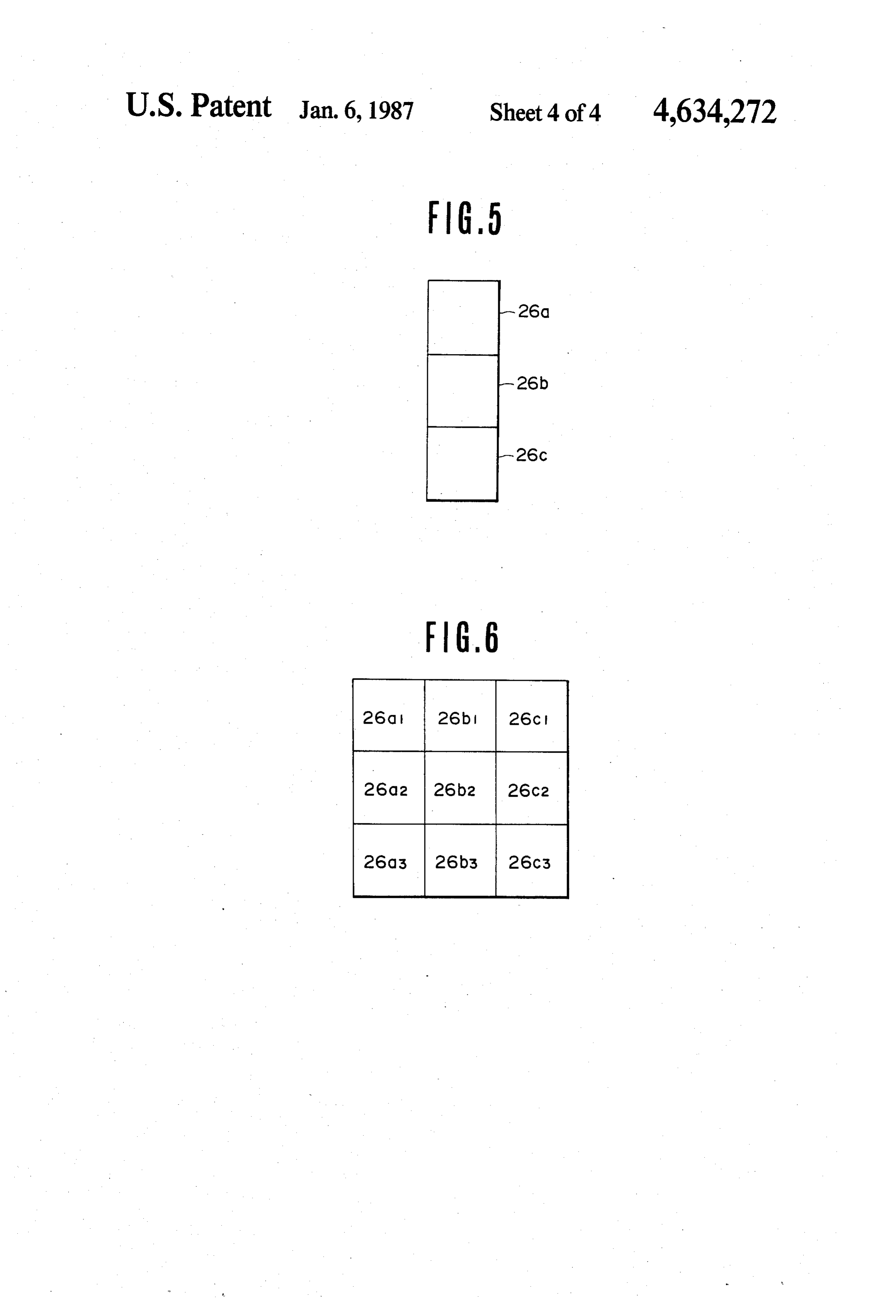
FIGS. 5 and 6 are illustrations of other arrangements
OPTICAL RADAR SYSTEM WITH AN ARRAY OF of photo-sensitive elements.
PHOTOELECTRIC SENSORS
DETALED DESCRIPTION OF THE
BACKGROUND OF THE INVENTION 5 PREFERRED EMBODIMENT
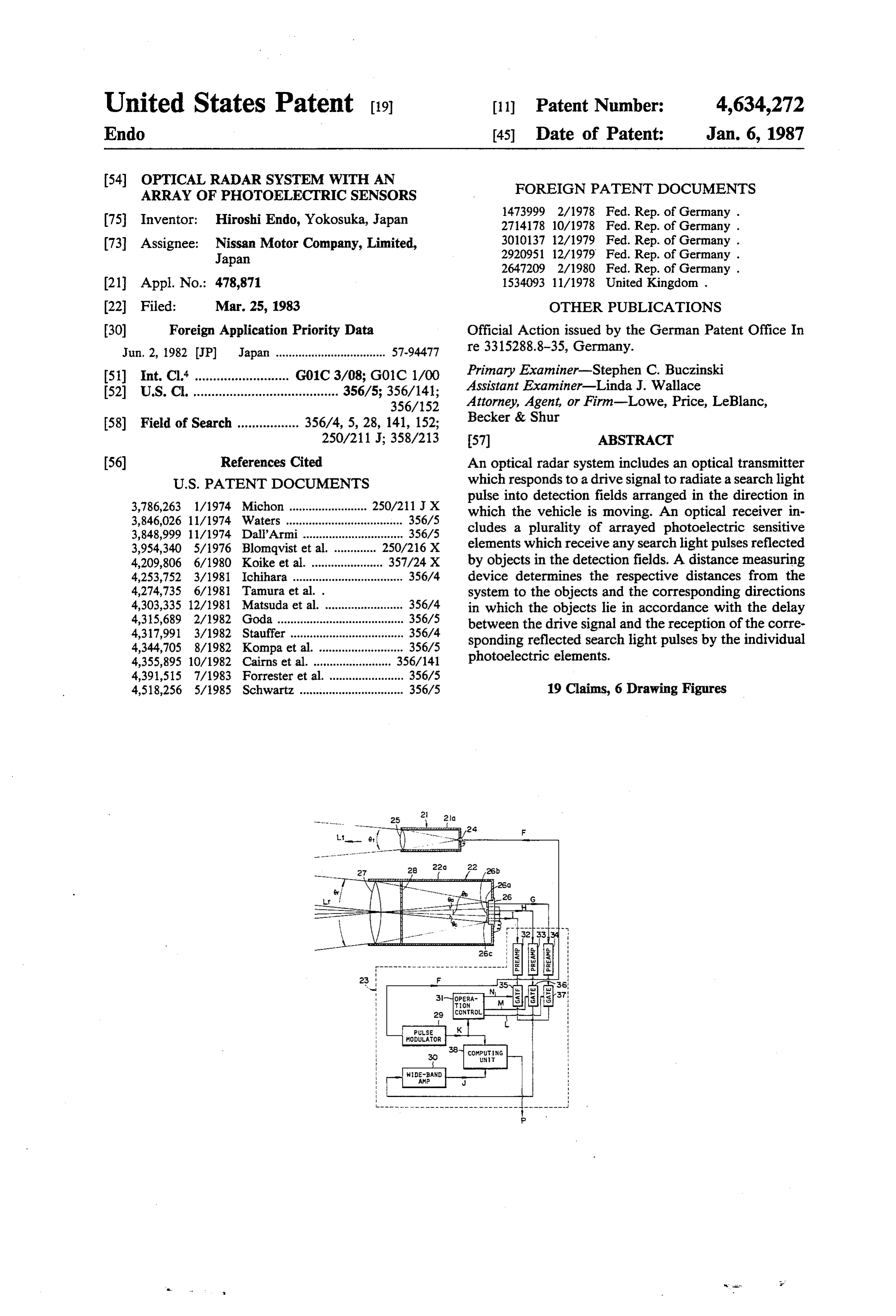
The present invention relates to an optical radar sys Referring to FIG. 1, there is shown a preferred em tem which determines the respective distances from the bodiment of an optical radar system according to the present invention. The system includes a phototransmit system to detected objects and the respective directions ter 21, an optical receiver 22 and a signal processor 23. toward the objects with respect to the system.
A conventional optical radar system adapted to be 10 Phototransmitter 21 includes a light-emitting element mounted on the front of an automotive vehicle includes 24 positioned at one end of a housing 21a. The light emitting element 24 is activated by a drive signal F an optical transmitter, an optical receiver, and a signal produced processor. The transmitter radiates a search pulse of by a pulse modulator 29 of signal processor 23 coherent light produced by a semiconductor laser in a 15 to produce a search pulse Lt of coherent light. The beam having an appropriate angle of divergence toward housing 21a also supports a collecting convex lens 25 in the object to be detected. The optical receiver collects ament fixed spatial relationship with the light-emitting ele 24. Search pulse Lt is transmitted through the lens the light pulses reflected by the object using a lens, eliminates the background noise from the collected 25 towards objects to be detected in the form of a beam light pulses using an interference filter and focuses the 20 of coherent light with angle of divergence 0t. Light filtered light onto a single photo transducer. The result emitting element 24 may be a semiconductor laser. ing pulse signal from the photo transducer is amplified Optical receiver 22 collects the part Llr of search to an appropriate magnitude by a wide-band amplifier in lens signal Lt reflected by the objects by way of a convex the processor. A computing unit of the processor deter 27 positioned in a housing 22a, removes the back mines the distance from the radar system to the object in 25 ground noise light using an interference filter 28 behind accordance with the delay between the arrival of the lens 27 and focuses the filtered light onto a photoelec reflected pulse and the occurrence of a drive signal tric transducer 26 positioned at one end of housing 22a. which triggers the transmitted pulse of coherent light, The photo-sensitive surface of transducer 26 is made up as well known in the art. of three independent areas 26a, 26b and 26c aligned in In this conventional radar system, however, the area 30 the horizontal plane which includes the optical axis of of the light-receiving surface of the light sensitive ele thelens 27. Areas 26a, 26b and 26c are rectangular and of ment is very small so that the region in which the re same size.
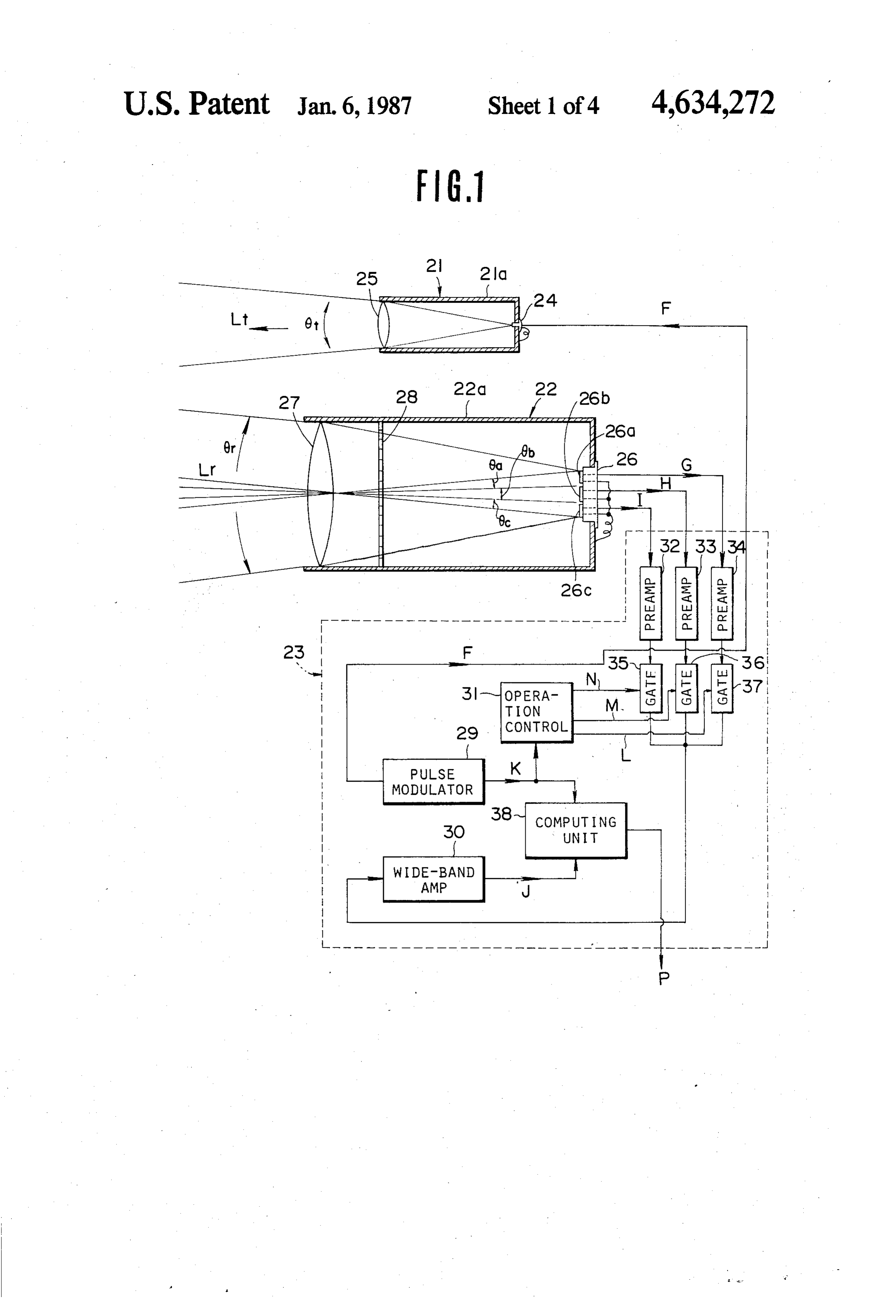
flected pulses can be sensed is limited to a very small The range 0r over which photoelectric transducer 26 area forward of the optical receiver. For example, when can sense reflected light Lr is the sum of the sub-ranges 6a, 0b and 6c of each of the respective areas 26a, 26b an automotive vehicle is travelling along the axis of the 35 and 26c, as shown in FIG. 2.
transmitted pulse beam forwardly of the automotive
If the distance between an object 40 and lens 27 is vehicle on which the optical radar system is mounted, represented the distance between the preceding vehicle and the tance between by R, the focal distance by f, and the dis following vehicle can be computed. However, when by l, the following lens 27 and photoelectric transducer 26 the preceding vehicle leaves the sensible area due to a formula holds: curved or sloped road, the radar system gives out infor 1/R-1/l= 1/f (1) mation such as would be given out when there are no preceding vehicles, which is an undesirable matter. Since R is much greater than f, l essentially equals f. SUMMARY OF THE INVENTION Thus, the reflected light Lr is focused onto photoelec
According to the present invention, an optical radar tricIftransducer the
dimensions of each of the rectangular light system includes an optical receiver which in turn in receiving areas 26a, 26b, 26c have length m and width n, cludes a plurality of arranged photoelectric sensitive the respective detection field angles 6a, 6b and 6c and elements, and a distance measuring device which deter the transverse detection field angle 6y are given by: mines the respective distances from the system to ob 50 jects and the respective directions toward the objects 0a = 0basecat2 tan-m/2f (2) with respect to the system in order to find objects and avoid possible obstacles in the directions in which the 6 vs 2 tann/2f (3) vehicle equipped with the system moves.
Signal processor 23 determines the respective dis
BRIEF DESCRIPTION OF THE DRAWINGS 55 tances from the system to the objects lying within the
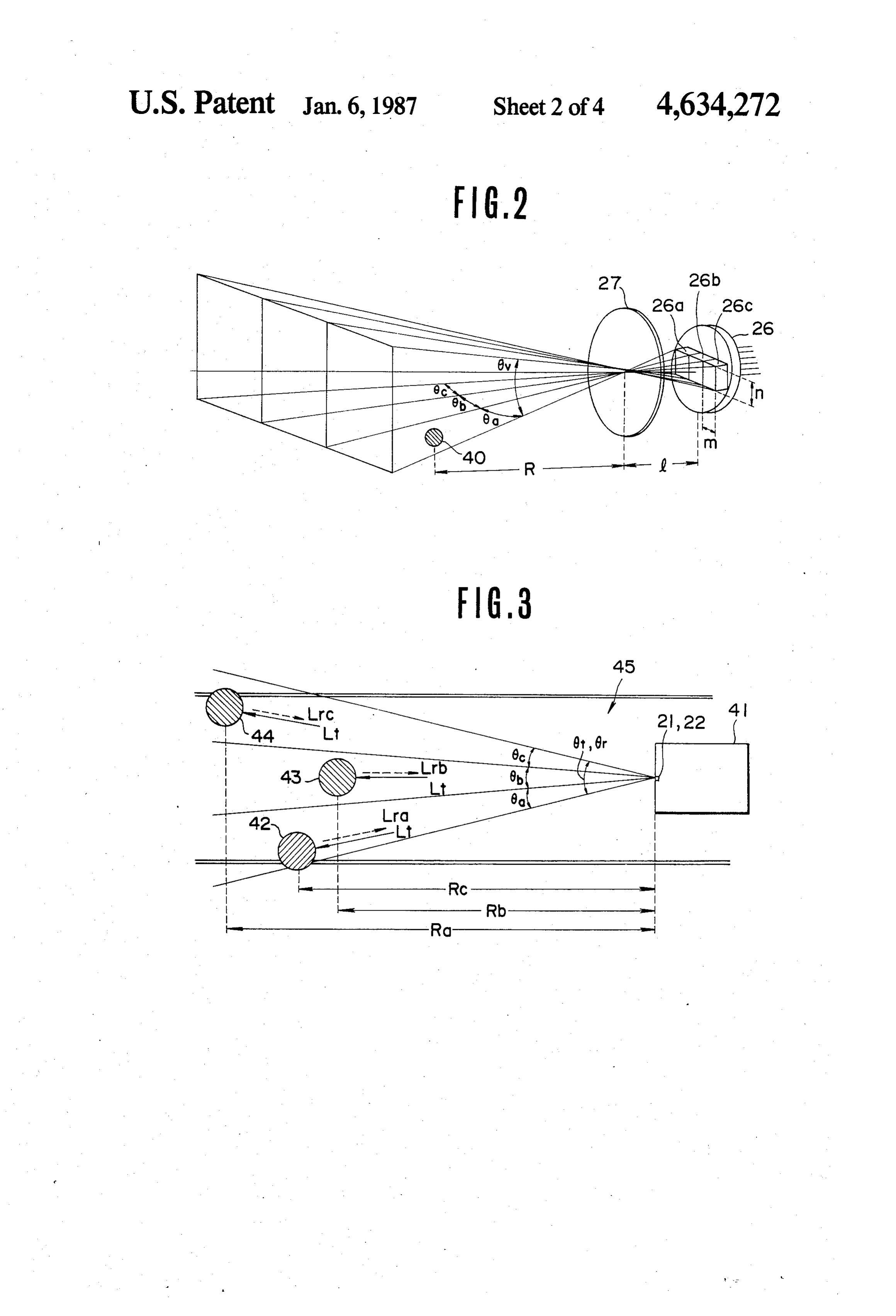
In the drawings: detection fields corresponding to transducers 26a, 26b FIG. 1 is a schematic illustration of a preferred em and 26c on the basis of the electrical signals G, H and I bodiment of an optical radar system according to the from transducers 26a, 26b, 26c, respectively. The pro present invention; cessor includes preamplifiers 32, 33 and 34 which am FIG. 2 is an illustration of the combination of arrayed plify the electrical signals G, H and I respectively, an photo sensitive elements and a lens and the resulting operation control unit 31 which repeatedly produces detection zones; respective gating signals L, M and N in a fixed time FIG. 3 is an illustration of the geometry of detection sequence in response to the pulses of a triggering signal of several objects lying in different directions with re 65 K from pulse modulator 29 in synchronism with the spect to the axis of the radar system; pulses of drive signal F, gates 37, 36 and 35 opened by FIG. 4 is a timing chart of the operation of the radar gating signals L, M and N respectively, a wide-band system according to the present invention; and amplifier 30 which respectively amplifies and shapes the
Page 7
signals G, H and I sequentially outputted by preamplifi signal and then photoelectric sensitive element 26c out ers 32, 33, 34 and a computing unit 38 which determines puts a signal and subsequently stops outputting the sig the respective distances from the system to the objects nal. This fact indicates that the detected vehicle may in accordance with the timing J of the output of wide have entered a curve to the right with respect to the band amplifier 30 and triggering signal K and outputs 5 directions shown in FIG. 3.
distance data P for each of the detection fields in which While the above embodiment employs a plurality of an object is present. photoelectric sensitive elements aligned transversely in The operation of the optical radar system according a single line, the photoelectric sensitive elements may to the present invention will be described with respect alternatively be aligned vertically in a single line, as to FIG. 3 in which the detection of three objects is 10 shown at 26a, 26b, 26c in FIG. 5, or may be arranged in illustrated. As shown, phototransmitter 21 and optical a matrix, as shown at 26a1, 26a2, 26.a3; 26b1, 26b2, 26b3; receiver 22 of the system are centrally mounted on the 26c1, 26c2, 26c3 in FIG. 6.
front end of the vehicle body. The angle of divergence An increase in the number of photoelectric sensitive 6t of search beam Lt from transmitter 21, which natu elements would enable the sizes and shapes of objects to rally equals the angular detection range 6r of optical 15 be sensed.
receiver 22, is chosen so as to approximately cover the Such an optical system may be mounted on airplanes width of the road lane (e.g., about 3.5 m) when a safe for the same purpose.
inter-vehicle distance (e.g., about 50 m) is maintained. While the present invention has been described and The photo-sensitive elements 26a, 26b and 26c are set to shown in terms of a preferred embodiment thereof, it is sense reflected light from the left-forward, central-for 20 not limited to the particular embodiment. Various ward and right-forward directions respectively with changes and modifications could be easily made by respect to the axis of the system. those skilled in the art without departing from the scope Assume that drive signal F having period Tp and of the present invention as set forth in the attached pulsewidth Tw, as shown in FIG. 4(b), is outputted by claims.
pulse modulator 29, and a search light pulse having 25 What is claimed is:
wavelength , and pulsewidth. Tw is transmitted. If 1. A system for measuring a distance to an object, there are moving objects such as motorcycles 42, 43, 44 comprising:
at respective distances Ra, Rb and Rc in front of the a first means responsive to a predetermined drive radar system within the detection fields 6a, 6b and 6c, signal for transmitting a coherent pulsating light to the light pulses Lira, Lrb and Lrc reflected by the re 30 a detection region of predetermined dimensions spective motorcycles and returning to photo-receiver and orientation with respect to the system; 22 arrive at receiver 22 delayed respectively by times b. second means including means for collecting a ta, Tb and Tc with respect to the timing of transmission portion of the coherent pulsating light reflected by of searchlight Lt, as shown in (d), (f) and (h) in FIG. 4. the object in the detection region and a plurality of The reflected light pulses Lira, Lrb and Lirc received by 35 arrayed photo-sensitive elements each monitoring receiver 22 are focused by lens 27 onto photoelectric a distinct light receiving area of said detection elements 26a, 26b and 26c which output signals G, H. region and receiving the collected coherent light and I indicative of the reflected light pulses Lira, Lrb reflected from objects therein; and and Lrc, respectively to signal processor 23. Signals G, c. third means for generating and outputting the drive H and I are amplified by 20-30 dB by preamplifiers 32, signal to said first means and determining the dis 33 and 34 and outputted to gates 35, 36 and 37, respec tance to the object in the detection region on the tively. basis of the difference in time between an output Gates 35, 36 and 37 are supplied with gating signals timing of the drive signal and timing of reception of L, M and N, as shown at (), (k), and (l) in FIG. 4, which a received electric signal derived from each said go high sequentially in response to triggering signal K, 45 light receiving area of said plurality of arrayed as shown in (a) in FIG. 4 in synchronism with drive photo-sensitive elements, signal F from operation control unit 31 to cause signals said third means comprising means for sequentially G, H and I to pass alternatingly through the corre processing the received electric signals from each sponding gate. The output terminals of gates 35, 36 and of said plurality of photo-sensitive elements within 37 are connected so that the sequentially gated pulses 50 a sequence of predetermined time periods and G, H, and I are concatenated to form a serial signal, as means for measuring a time within each of said prede shown in (m) in FIG. 4. Wide-band amplifier 30 ampli termined time periods for reception of reflected fies and shapes the serial signal pulses into a timing light by the photo-sensitive elements, signal, J, such as is shown at (n) in FIG. 4, outputted to thereby determining a time for transit of said light computing unit 38. Computing unit 38 determines the 55 pulse to an object in said light receiving area moni distances Ra, Rb and Rc to respective objects 42, 43, tored by the photo-sensitive elements. and 44 on the basis of the respective delay intervals ta, 2. The system according to claim 1, wherein said Tb and Tc of timing pulses of signal J with respect to the third means includes means for sequentially determining corresponding pulses of trigger signal K and outputs the distance between the system and each object. distance data P for each of the detection fields in which 3. The system according to claim 2, wherein said an object is present. plurality of arrayed photo-sensitive elements are As described above, the possible movement of ob aligned horizontally in a single line.
jects can be predicted by monitoring changes in the 4. The system according to claim 2, wherein said distances to the objects in the right-, left- and central plurality of arrayed photo-sensitive elements are forward detection fields with respect to the axis of vehi 65 aligned vertically.
cle 41. For example, assume that at first a vehicle is 5. The system according to claim 2, wherein said detected within the central detection field so that pho plurality of arrayed photo-sensitive elements are ar toelectric sensitive element 26b is first outputting a ranged in the form of a matrix.
Page 8
6. The system according to claim 1 wherein said third plurality of detecting means comprising photo-sen means is further operable for determining an orientation sitive means; and of the object on the basis of said difference in time. distance measuring means for determining respective 7. Apparatus as recited in claim 1 wherein said means longitudinal distances to objects detected in corre for sequentially processing includes means for provid sponding detection areas, ing outputs of each of said plurality of photo-sensitive said distance measuring means comprising means for elements in a time-multiplexed arrangement to said sequentially processing the reflected signals de means for measuring time. tected by said plurality of photo-sensitive means 8. Apparatus as recited in claim 7 wherein said means within a sequence of predetermined corresponding for sequentially processing further includes gating 10 time periods and means for sequentially gating said outputs of said plural means for measuring a time within each of said prede ity of photo-sensitive elements onto a single line thereby termined time periods for reception of reflected to provide a concatenated sequence of signals to said light by the photo-sensitive means, means for measuring time for sequentially measuring thereby determining a time for transit of said light time differences between reflected light from sequential 15 pulse to an object in said detection area monitored ones of said photo-sensitive elements and a reference by the photo-sensitive means. time corresponding to a transmission time of said pulsat 13. Apparatus as recited in claim 12 wherein said ing light. plural photo-sensitive means are disposed in the vicinity 9. An apparatus as recited in claim 8 wherein said of said transmitter means.
gating means comprises a plurality of gates having re 20 14. Apparatus as recited in claim 12 wherein said spective input terminals respectively connected for providing means for sequentially processing includes means for receiving output signals from said outputs of said photo sitive means outputs of each of said plurality of photo-sen sensitive elements and having output terminals, said means for measuring in a time-multiplexed arrangement to said output terminals connected to said single line, and wide 25 15. Apparatus as recited time. band amplifying means connected to receive said output means for sequentially processing in claim 14 wherein said signals sequentially from said single line and for shaping ing means for sequentially gating further said includes gat outputs of said said output signals and for providing the shaped signals plurality of photo-sensitive means onto a single line to said means for measuring time. thereby to provide a concatenated sequence of signals 10. An optical radar system for a vehicle comprising: 30 said means for measuring time for sequentially mea a. an optical transmitter responsive to the pulses of a to suring time differences between reflected light from drive signal to emit corresponding pulses of light; sequential ones of said photo-sensitive means and a b. means for directing the propagation of each pulse reference time corresponding to a transmission time of so as to cover a predetermined detection region; said coherent light pulse.
c. a plurality of photo-sensitive elements, each re 35 16. An apparatus as recited in claim 15 wherein said sponsive to incident pulses of light to produce sen gating means comprises a plurality of gates having re sor pulse signals; spective input terminals respectively connected for d. means for focussing light reflected from said emit receiving output signals from said outputs of said photo ted light pulses by objects within said detection sensitive means and having output terminals, said out region onto said photo-sensitive elements such that 40 put terminals connected to said single line, and wide said detection region is subdivided into a plurality band amplifying means connected to receive said output of detection fields, the reflected light from each of signals sequentially from said single line and for shaping said fields being focussed onto exactly one of said said output signals and for providing the shaped signals photo-sensitive elements; and e. a processing unit responsive to said drive signal and 45 to 17.
said means for measuring time.
Apparatus as recited in claim 12 wherein said said sensor signals for sequentially determining distance measuring means comprises a delay measuring whether or not objects capable of reflecting light means for determining a time delay between transmis exist in any of said fields of said detection region sion of said signal by said transmitter means and detec and further for sequentially determining the dis tion of a reflected signal by any of said plurality of tance and direction to detected objects on the basis 50 detecting means to determine a distance to an object in of a time delay between pulses of said drive signal the corresponding detection area.
and corresponding pulses of said sensor signals. 18. Apparatus as recited in claim 17 wherein said 11. Apparatus as recited in claim 10 wherein said delay measuring means comprises means for detecting processing unit comprises means for sequentially en delays between transmission of said signal and detection abling passage of said sensor signals to a means for 55 of a reflected signal by each of said plurality of detect measuring a time of reception of said respective sensor ing means to compute longitudinal distances to each of signals within respective predetermined time periods a plurality of objects detected in a plurality of said trans thereby determining a time for transit of said light pulse verse detection areas.
to an object within said fields of said detection region to 19. A system for measuring a distance to an object, identify a distance between said object and the vehicle. 60 comprising:
12. Apparatus for determining longitudinal distances a first means responsive to a predetermined drive to objects in a plurality of transverse detection areas in signal for transmitting a sequence of timed coher a Zone, comprising: ent light pulses to a detection region of predeter transmitter means for transmiting a coherent light mined dimensions and orientation with respect to pulse longitudinally to said zone, 65 the system;
a plurality of detecting means each operable for de b. second means including means for collecting a tecting presence of an object in a corresponding portion of the coherent light pulses reflected by the one of said transverse direction areas, each of said object in the detection region and a plurality of
Page 9
arrayed photo-sensitive elements each respectively tive elements monitoring said respective light re monitoring a distinct light receiving area of said ceiving areas, and detection region and receiving the collected cohere d. Synchronizing means for gating each of said ar ent light reflected by said object; rayed photo-sensitive elements for a predetermined . . third means for generating and outputting the drive 5 time period in respective synchronization with said signal to said first means and determining the dis timed light pulses and for measuring a time dura tance to the object in the monitored areas of said tion within each predetermined time period, said time duration indicative of a time between trans detection region on the basis of the difference in mission of said:light pulse and collection of said time between timing of the drive signal and timing O portion of said light pulse from an object in said of reception of a received electric signal derived respective light receiving areas monitored thereby. from each of said respective arrayed photo-sensi ; ; ; ; ; ; ; ; ; ;
Provenance
- Collection
- Cited prior art
- Original PDF
- patentimages.storage.googleapis.com →
- Filed
- 1983-03-25
- Pages
- 9
- Method
- pdftotext (the PDF's own text layer) + pdftoppm 300dpi page scans
- Source
- Google Patents bibliographic record
- Granted
- 1987-01-06
- Inventors
- Hiroshi Endo; Nissan Motor Co Ltd
- Transcribed from
- patentimages.storage.googleapis.com →