patent · US4596990
Multi-jet single head ink jet printer
24 June 1986
Page 1 — bibliographic record
United States Patent (19) 11) Patent Number: 4,596,990 Hou 45 Date of Patent: Jun. 24, 1986 54 MULTI-JET SINGLE HEAD INKJET 4,091,390 5/1978 Smith .................................... 346/75 PRINTER 4,194,210 3/1980 Krause .................................. 346/75 4,303,925 12/1981 Harbour.... ... 346/75 X 75 Inventor: Shou L. Hou, Radnor, Pa. 4,346,393 8/1982 Wallace ............................... 346/140 73 Assignee: TMC Company, Wayne, Pa. 4,374,387 2/1983 Iyoda ..... ... 346/75 4,401,991 8/1983 Martin ... ... 346/75 21 Appl. No.: 626,651 4,429,315 l/1984 Tamai.................................... 346/75 22 Filed: Jul. 2, 1984 OTHER PUBLICATIONS Pawletko et al.; High Speed Printer, IBM Tech. Disc.
Related U.S. Application Data Bulletin, vol. 19, No. 9, Feb. 1977, pp. 3355-3356. 63 Continuation-in-part of Ser. No. 343,288, Jan. 27, 1982, Pelkie et al., Ink Jet Head, IBM Tech. Disc. Bulletin, abandoned. vol. 20, No. 2, Jul. 1977, pp. 553-554. 51) Int. Cl. ............................................. GOD 15/16 Fillmore et al., Ink Jet Splatter Reduction with Double 52 U.S. C. ................................. 346/75; 346/140 R; Throughput, IBM Tech. Disc. Bulletin, vol. 21, No. 2,
58) Field of Search ............................. 346/75, 140, 1; Primary Examiner-Joseph W. Hartary 400/126 Attorney, Agent, or Firm-Dann, Dorfman, Herrell and 56) References Cited Skillman
3,298,030 l/1967 Brown ................................... 346/75 A multi-inkjet printer contains in nozzle orifices, which 3,373,437 3/1968 Sweet & Cumming .............. 346/75 are aligned in one or two nozzle orifice arrays with its 3,562,757 2/1971 Bischoff ................ . 346/75 X axis (or axes) substantially parallel to the relative print 3,586,907 6/1971 Beam et al. ........................... 346/75 direction. All print droplets generated from nozzle ori 3,596,275 7/1971 Sweet ........ 346/75 X fices are individually charged and are deflected under a 3,689,.693 9/1972 Cahill ................................ 346/75 X common deflection electric field substantially perpen 3,714,928 2/1973 Taylor. 346/75 UX 3,786,517 1/1974 Krause .................................. 346/75 dicular to the relative print direction. All nozzle orifices 3,813,676 5/1974 Wolfe .................................... 346/75 may be individual single jets, or may be formed on an 3,828,354 8/1974 Hilton ........... . 346/75 X orifice plate sharing the same ink system, same stimula 3,836,913 9/1974 Burnett et al. ........................ 346/75 tion, same deflection electrodes and the same ink collec 3,877,036 4/1975 Loeffler ................................ 346/75 tor. Using the interlacing schemes described in this 3,900,162 8/1975 Titus ..... 346/75 X teaching, the said multi-inkjet printer can print marks, 4,010,477 3/1977 Frey ...................................... 346/75 characters, or graphics on receiving medium at n times 4,059,183 11/1977 Hoskins ............................. 346/75 X the print speed of a single jet printer and still maintain 4,060,804 11/1977 Yamada ... ... 346/75 X 4,069,486 1/1978 Fox ....................................... 346/75 ing excellent print quality.
4,074,278 2/1978 Robertson ............................. 346/75 4,079,824 3/1978 Ku ....................................... 400/124 21 Claims, 15 Drawing Figures RELATEDIRECo of on
sex ešSeš
a SPACA belAY
In SPACIAL DELAY:
PRINT Recto
Page 2
Drawing sheet — no readable text.
Page 3
Drawing sheet — no readable text.
Page 4
Drawing sheet — no readable text.
Page 5
Drawing sheet — no readable text.
Page 6
at each voltage will either allow that deflection voltage
MULT-JET SINGLE HEAD INKJET PRINTER to be imposed on the charging electrode or typically in most printers completely removes voltage to allow the
This is a continuation-in-part application of U.S. pa ink to be caught in the ink gutter positioned to catch tent application Ser. No. 343,288, filed Jan. 27, 1982 5 uncharged particles and recirculate them to the reser now abandoned. voir for reuse. m The present invention relates to the use of more than In another configuration, the print head which con one jet in a single head inkjet printer to accomplish tains a jet nozzle and deflection plates may be held faster and more effective printing, while maintaining an stationary, while the receiving medium (paper or ob excellent print quality for serial printers. The multi-jet 10 jects) may be moved by transport means to produce the nozzles are aligned in a straight line substantially paral same mark, character, or graphics as the moving print lel to the relative printing direction, while droplets from head printer previously described. each jet (or nozzle) are deflected under the deflection electric field in a direction substantially perpendicular beInelectrostatic the prior art, it has been understood that there can to the printing direction. An interlacing technique is 15 lets but there is ainteraction between adjacent ink drop certain tolerance to error which can be used to assure quality as good as that of a single continu ous jet printer, but it yields a print speed n-times faster, accommodated ably less than 30 to the droplet placement. This is prefer microns for a resolution of 240 dots per where n is the number of nozzles in the inkjet array inch (or 10 dots/mm) and less than 25 for 300 dots printer. The present invention also relates to the method /inch printing (or 12 dots/mm.). In the prior art, vari of interlacing to produce that printing. 20 ous techniques were employed for minimizing this er
STATE OF THE ART ror. One of these was the use of guard drops as taught At the present time there are available from various by U.S. Pat. No. 3,562,757, issued February, 1971, to V. sources continuous single jet printer devices. Such a Bischoff. Also, there are charge compensation schemes printer has an ink reservoir which is under a constant 25 such as illustrated by U.S. Pat. No. 3,828,354, issued pressure of typically 16 to 80 pounds per square inch. Aug. 6, 1974, to H. T. Hilton. However, such known The pressure causes the ink filament ejected from a processes have also reduced the number of printing droplets by a factor of 2 to 3 depending, for example, small orifice of 20 to 50 microns in diameter toward a small well-defined area of the paper or other receiving tween upon the number of non-charged droplets placed be medium to be printed which paper is supported a fixed 30 charged, the printing droplets. If every other droplet is not distance from the nozzle on a suitable platen. Under the If only every the printing speed is reduced by a factor of 2. stimulation of an ultrasonic wave, the filament is broken other third droplet is potentially capable into a stream of well-defined ink droplets at a rate equal of charge, printing speed is reduced by a factor of 3. to the frequency of the superimposed ultrasonic wave. An inkjet printer of the present invention may be of Through charge induction, droplets are charged one by 35 the type shown in U.S. Pat. No. 3,596,275, issued July one before break-up and the amount of charge causes 27, 1971, to R. G. Sweet or U.S. Pat. No. 3,298,030, each droplet to deflect generally perpendicular to the issued January 1967, to A. Lewis and D. Brown. The printing direction in proportion to the charge imposed. process has produced 240 dots/inch (or 10 dots/mm.) The droplet is deflected under the influence of an elec printing at 92 characters per second at 12 pitch. trostatic field produced by deflection means to a prede There is another approach using inkjet array. Nu termined position. In the course of each of the succes merous closely packed inkjet nozzles are aligned in a sive deflections a straight line, generally perpendicular straight line perpendicular to the printing direction. The to the print direction (usually a vertical line), or parts of non-charged droplets are used to print on paper; while a line, is drawn so that by drawing a series of closely the non-printing droplets are charged and deflected into spaced vertically oriented segments of lines the desired 45 a common gutter and are recirculated into its ink sys character is completed. The charge imposed on the tem. The process was first taught in U.S. Pat. No. droplets is varied in a predetermined stepwise fashion, 3,373,437, issued Mar. 12, 1968, to R. G. Sweet and R. but for each droplet there is the option of putting the C. Cumming. The process has been further developed charge at a level which causes the droplet to be directed at Mead Corporation as taught in U.S. Pat. No. to a gutter or ink catcher rather than impinging upon 50 3,586,907 to D. R. Beam et al, U.S. Pat. No. 3,714,928 to the paper. R. P. Taylor, U.S. Pat. No. 3,836,913 to M. Burnett et Typically, these non-printing droplets are not al, and U.S. Pat. No. 4,010,477 to J. A. Frey. charged and only the droplets used to draw the succes In this approach, an array with up to 1200 nozzles sive vertical line segments are charged. Successive ver have been aligned in a 25 cm. head in a direction per tical lines are drawn as a carriage supporting at least the 55 pendicular to the print direction. Since each nozzle is a inkjet orifice and charging electrode moves transverse single continuous jet and is printing in a binary mode, a to the jet deflection, usually horizontally across a line paper roll up to 10 inches width has been printed after on the paper on the platen for a serial printer. The passing under the print head only once at a speed in charge potential for successive droplets is increased or excess of 1000 feet perminute which is the fastest elec decreased in generally fixed predetermined steps so that tronic printer ever built to date.
if all of the droplets are allowed to impinge the paper, The approach has all nozzles share a common ink they will together draw a vertical line. Characters are System, a common ink reservoir, a common deflection produced by moving the carriage horizontally effec electrode, and a common ink collector. The cost is tively drawing a successive sequence of vertical line substantially less than those of 1200 single continuous segments at predetermined positions which are needed 65 jets.
to form the sequence of selected characters. Particle Limited by how closely we can pack nozzles per charge information for each possible character capable millimeter and by jet straightness obtained by today's of being printed is stored in a memory which typically fabrication technology (1 to milliradian), the print
Page 7
quality has not exceeded an equivalent of 240 dots/inch The vertical matrices printed by different nozzles in the (or 10 dots/mm.). array will interlace to form a high resolution character. PRESENT INVENTION Means are provided to produce relative movement between print head and receiving medium substantially
The present invention is directed to a print head con- 5 taining from 2 to n jets. All jets are aligned in a straight parallel to the axis of nozzle alignment. line substantially parallel to the relative printing direc jet "1" will printifevery
For example, the array head contains two nozzles, even number of vertical matri tion. Each jet deflection is in a direction substantially ces, while the jet "2" will perpendicular to the print direction. Proper delay is vertical matrices. There is aprint every odd number of time delay for jet '2' with provided to each jet during printing to maintain a good 10 respect to jet "1" by (d+1/R)/10V seconds where: printing quality. By the use of the multiple jets the print d is the inter jet spacing in mm., ing speed will be increased 2 to n times faster depending R is the resolution in dots/mm., and upon the number of jets used. At 12 characters per inch V is the relative printing speed in cm./sec; or a spa printing, a high resolution character needs 640 print droplets at 10 dots/mm. (or 240 dots/inch) resolution; 15 It cial delay of (dR 1) dotted lines. will then be understood that the distance between and needs 1000 print droplets at 12 dots/mm. (or 300 dots/in.) resolution. While at 5 dots/mm. (or 120 dots centers of two nozzles must be a multiple integer of the /inch) resolution, only 160 print droplets are sufficient inter-dot distance between centers for the given resolu to form a character. A typical continuous inkjet oper tion.
ates at about 100,000 droplets a second. Hence, a typical 20 If three nozzles are used, each nozzle prints only single continuous jet printer prints about 50 characters every third vertical matrices, i.e., per second at 12 dots/mm. resolution; about 80 charac jet "l' prints (3mE1)th dotted line; ters per second at 10 dots/mm. resolution; and about jet '''2'' prints (3mE2)th dotted line; 310 characters per second at 5 dots/mm. resolution. jet "3" prints (3mE3)th dotted line; The following table lists the printing speeds as a func- is where m is an integer. The time delays with respect to tion of process and a number of jets: jet "1" are, (d+1/R)/10V seconds for jet "2"; and TABLE I (2d-E2/R)/10V seconds for jet "3", or there are spacial
Printing Speed Vs Number of Jets per Head delays with respect to jet "1" by (dR+1) dotted lines at 132,000 droplets/second for jet "2", and (2dR-2) dotted lines for jet "3". Number of Jets/Head 2 4 30 In general, if there are n nozzles in a single head 12 2-guard-drop 44 cps 88 cps 176 cps 44 n cps separated by a distance d between centers (d is also an dots/mm scheme integer of 1/R), each nozzle will print every nth dotted 1-guard-drop 66 cps 132 cps 264 cps 66 n cps line apart. In particular, the Kth jet in the array will scheme
O 2-guard-drop 68 cps 136 cps 272 cps 68 in cps print every (mn-K)th dotted line, while the first jet dots/min scheme 35 will print every (mini-1)th dotted line, where n is an 1-guard-drop 103 cps 206 cps 412 cps 103 n cps integer. There exists a time delay for the Kth jet with scheme 5 2-guard-drop 275 cps 550 cps 1100 cps 275 in cps respect to the first jet by (K-1)(d+1/R)/10V second, dots/mm scheme or a spacial delay of (K-1)(dR-El dotted lines. 1-guard-drop 412 cps 825 cps 1650 cps 412 in cps Let us now examine the electrostatic interaction be scheme 40 tween charged droplets on flight between two adjacent jets which could effect the droplet placement error.
At 12 dots/mm., a single continuous jet printer has a Electrostatic Coulomb force between two charged par quality and speed comparable with that of a daisywheel ticles of adjacent jets is printer. There is very little price performance advan tage over a daisywheel printer. By adding multi-nozzle q192 to the print head, the present invention offers a printing speed increase by n-times (where n is the number of nozzles in a single print head), while maintaining the same high resolution quality. Furthermore, the addi where the q is the charge contained in the droplet "i", r is distance between the droplets of adjacent jets, and
tional structure required in accordance with the present K is a constant.
invention is relatively nominal. The parts are known charged dropletsNote that the closest distance between from 2 adjacents jets is the distance and easily fabricated and many parts can be used in between the jet nozzles which as a practical proposition common such as the ink system, the deflection plates, the gutter and recirculation system. Hence, the process is taken to be 1-3 mm. At 132,000 droplets/sec. and a is cost effective. 55 droplet velocity of 2000 cm./sec., the inter-droplet The following are the descriptions of this invention. spacing for a single jet is 0.152 millimeters, the inter The present invention has the inkjet nozzles aligned droplet spacing is 7 to 20 times closer than the inter-jet in a straight line and is in parallel with the relative print spacing. Since Coulomb force is inversely proportional direction. Each nozzle is capable of producing a stream to the square of the distance, correction due to adjacent of ink droplets. Each droplet is properly charged to a jet is very small. Hence, one can ignore both the elec pre-determined level and is able to be deflected by the trostatic correction as well as the aerodynamic wake deflection electric field to a maximum deflection of at effect for droplets between jets. least 1.35 times the character height perpendicular to More specifically, the inkjet printer apparatus of the the print direction. In other words, each nozzle in the present invention employs an ink chamber or reservoir inkjet printer prints exactly like the inkjet printer de 65 having at least two matched orifice nozzles aligned scribed in the Sweet patent and Lewis and Brown pa parallel to the relative print direction. Means of con tent. When multi-nozzle print head is used as described, stant pressure or of constant flow is employed to apply each nozzle will print a portion of the vertical matrices. pressure to the reservoir to force ink out through each
Page 8
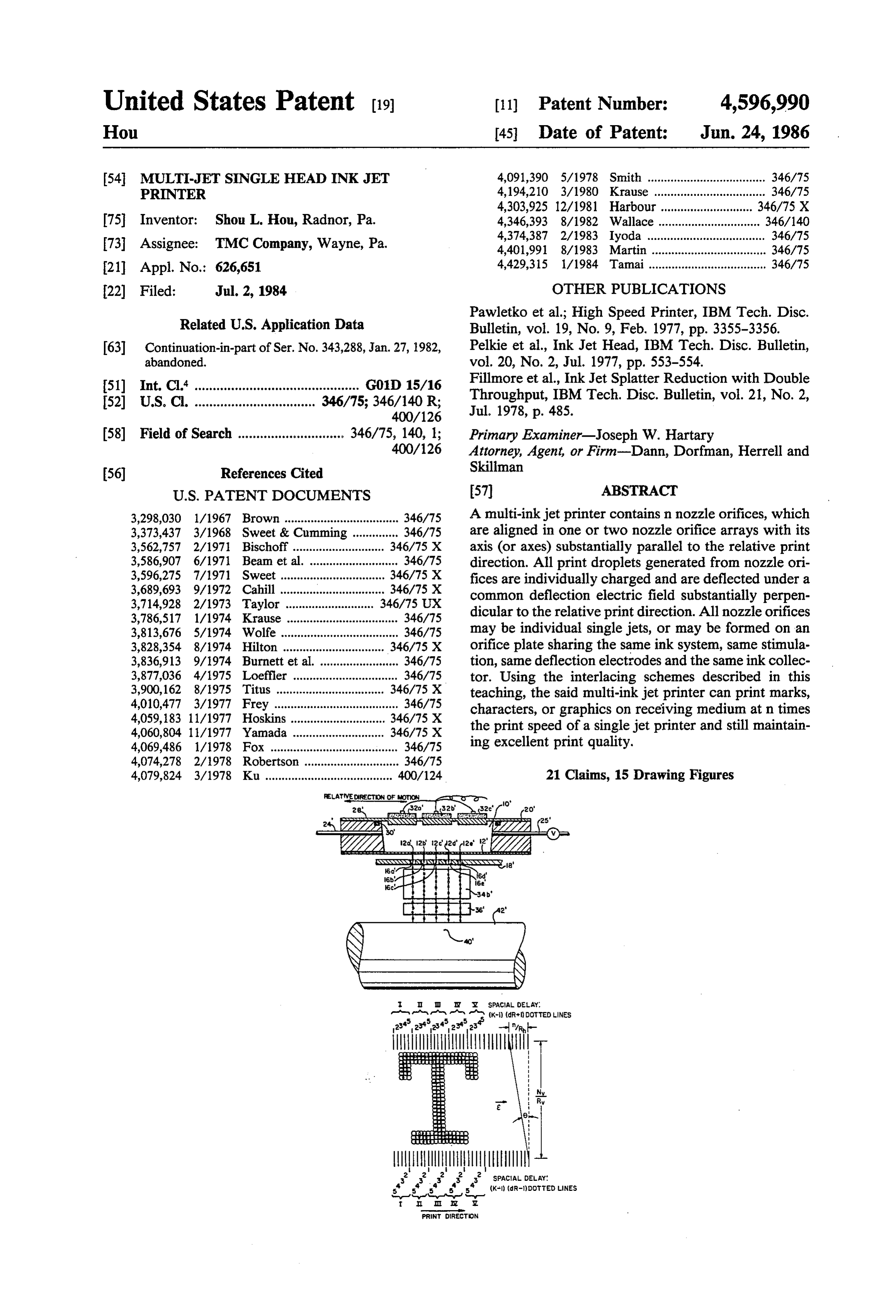
of said orifices in a thin filament, including means ac 2nth dotted line by the first jet by (d-1/R)/10V sec coustic energy means generating waves of the same onds where "d' is in the inter-jet spacing in millimeters, phase being preferred, acting on the ink to break the "V" is the relative print speed in cm/sec., and “R” is filament into droplets of predetermined size, each drop resolution in dots per millimeter. The spacial delay is let being of a size to produce a dot of predetermined size expressed (dR+1) dotted lines. in a roster of dots forming a printed character. Deflec DRAWINGS OF THE PRESENT INVENTION tion plates are positioned so that all of the droplets pass in droplet paths from the respective nozzles each in The present invention will be better understood by planes, transverse to the deflection plates. Deflection reference to the accompanying drawings in which: voltage supply means is connected to the deflection 10 FIG. 1 is a side elevational view of a two jet version plates to impose an electrostatic field between the de of the present invention in a partial sectional view or in flection plates. Charging electrode means is fixed rela the section as taken through the charging electrode ring tive to each orifice nozzle in position adjacent to the and deflecting plate along the paths from one orifice; respective orifice nozzles along the droplet paths from FIG. 2 is a plan view from above partially in section that nozzle. Electrostatic shielding means may be inter 15 showing a section through the jet path at orifice level at posed between adjacent charging electrodes to isolate both orifices and the bottom plate of the deflection charge effects imposed on droplets of one stream from plates;
droplets of another. A source of voltage is connected to FIG. 3 is an alternative construction shown in a view the respective charging electrode means. Each charg similar to that of FIG. 1;
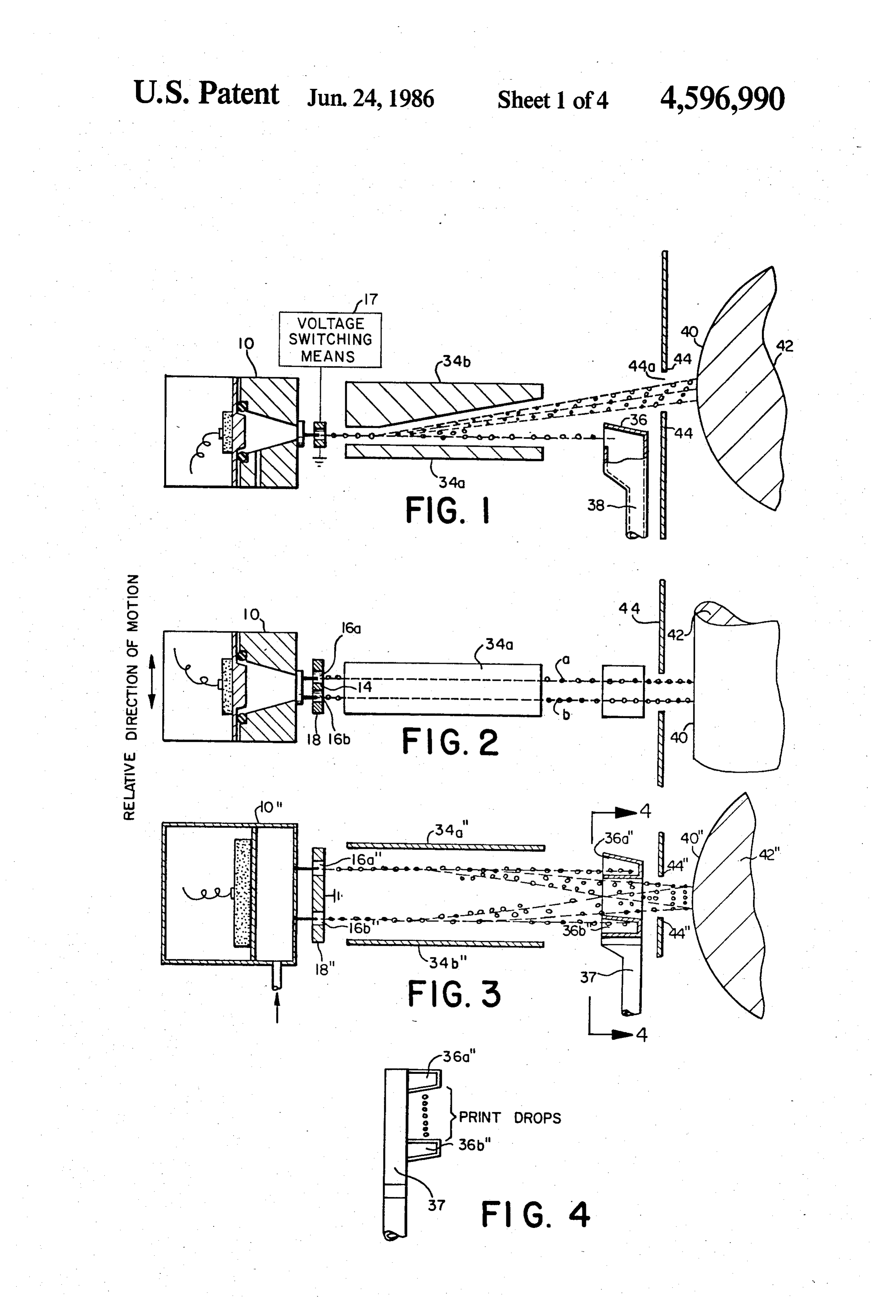
ing electrode, in turn, is capable of inducing electro 20 FIG. 4 is a detail view taken along line 4-4 of FIG. static charge on the individual droplets as they break off 3 showing a modified ink collector means; from the ink filament emerging from the orifice associ FIG. 5 is a side sectional view of printer head in FIG. ated with the charging electrode. The droplets are then 1;
deflected into paths determined by their respective FIG. 6 is sectional view taken along line 6-6 of FIG. charges as they pass through the field imposed by the 25 5;
deflection plates. Voltage switching means is provided FIG. 7 is a front view of the inkjet head as seen from for applying in a prearranged order selected voltages line 7-7 of FIG. 6;
(which may include Zero voltage) to each charging FIG. 8 is a sectional view taken along line 8-8 of electrode, as the individual droplets pass through. The FIG. 5;
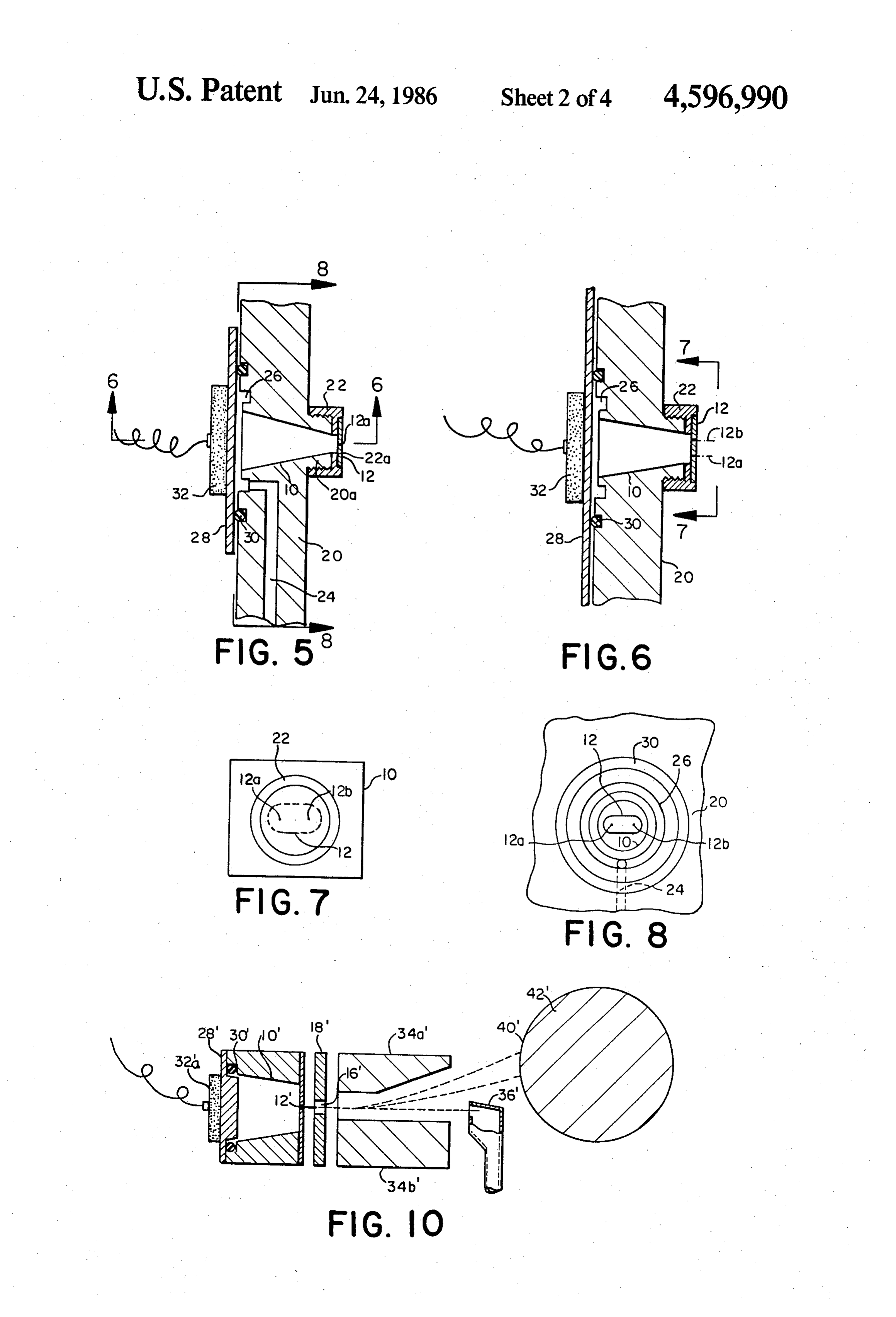
selected level of voltage induces charge on each droplet 30 FIG. 9 is a schematic drawing representing a five jet to follow a predetermined droplet path to a predeter version of the present invention;
mined position on a receiving medium. Ink collector FIG. 10 is a side sectional view across any one of the means is positioned for collection of non-print ink drop jets in FIG. 9;
lets for all nozzles moving along the predictable paths FIG. 11 illustrates how a letter "T" is printed by the generated by a particular selected level of voltage typi 35 five jet printer;
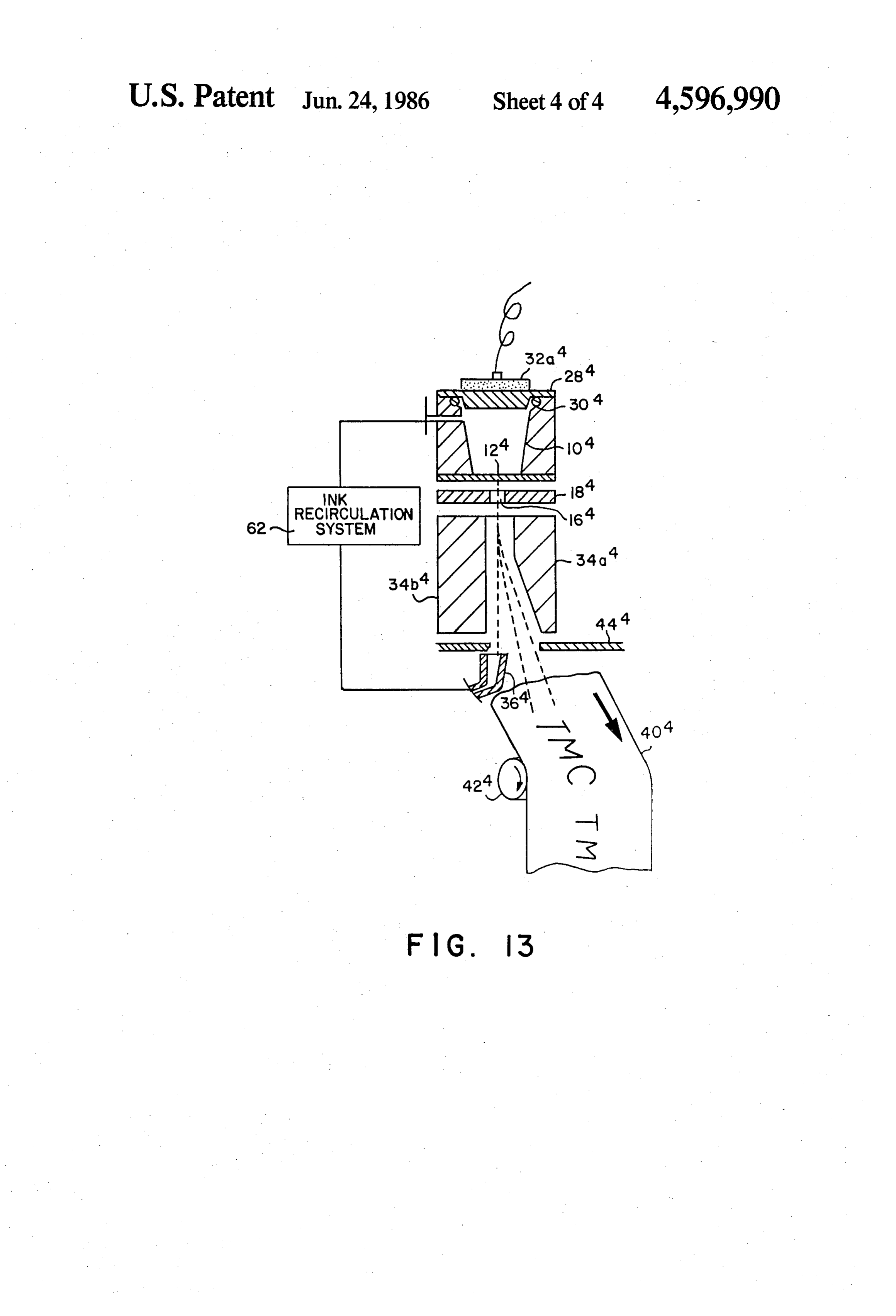
cally at zero potential. Means is supplied for supporting FIGS. 12A, 12B and 12C are fragmentary perspec receiving medium in position such that droplets moving tive views of different configurations of changing elec along paths in a plane from an orifice nozzle will im trodes; and pinge the supported receiving medium at points along a FIG. 13 shows one of the many possible means of line opposite that orifice nozzle and parallel to a line 40 moving an ink receiving medium relative to fixed nozzle opposite another orifice nozzle upon which droplets orifices.
from said other nozzle impinge. In one embodiment, SPECIFIC EMBODIMENTS OF THE PRESENT carriage is provided for moving together the orifice INVENTION nozzles and charging electrode means, and usually the deflection means and other ink system related elements 45 Referring now to the drawings, FIGS. 1 and 2, 5, 6, relative to the means supporting the receiving medium 7 and 8 illustrate a preferred embodiment. Much of the paper transverse to the plane of droplet paths from a system is known to be conventional. Much of it has been particular nozzle. In other embodiments, the print head shown in schematic form since the actual physical form containing an array of nozzles aligned in an axis, charg is well known. Thus, for example, in FIGS. 1 and 2, the ing electrodes, and deflection electrodes are held sta SO ink chamber 10 is shown schematically. The orifice tionary, while the receiving medium is moved in a di nozzles through which ink filaments are ejected from rection substantially parallel to the axis of nozzle ori the reservoir are best seen as nozzles 12a and 12b in an fices. Thus, it should be understood that the present orifice plate 12. The use of two nozzles in this configu invention is directed broadly to relative movement ration is new. A support structure 18 of insulating mate between the print head and the receiving medium. Any 55 rial supports ring charging electrodes 16a and 16b, be type of relative movement, consistent with the opera tween which is provided a conductive electrostatic tion of a print head, between the print head nozzles and shield 14 of conductive material. receiving media of unlimited variety, is contemplated to Considering FIGS. 5 and 6 briefly, it will be seen that be within the scope of the present invention. the reservoir structure is more representative of an The method of the present invention involves either actual form which would be employed. The reservoir manually or automatically, as by computer, delaying provides a cone-shaped cavity in a block 20 provided the printing of intermediate lines until the second nozzle with a cylindrical extension 20a the outside surface of orifice catches up with the position adjacent to the first which is threaded to engage the threads of a cap 22. The nozzle orifice was in when it printed the line adjacent to cap closes the narrow end of the conical cavity and is which the new line is to be printed by the second noz 65 provided with the orifices 12a and 12b on an orifice zle. In accordance with the present invention, the pat plate 12, Ink is fed into the cavity 10 through a conduit tern of dots in the (2n+1)th dotted line printed by the 24, preferably from a sump fed from the return means second jet is delayed from the time of the printing of the from the gutter (to be described) through a suitable
Page 9
pump which supplies pressure at a constant rate, typi mounted in the other side of the metal cover for stimula cally about 16 to 80 pounds per square inch. The ink is tion. For maximum transfer of acoustic energy, the fed into the ink chamber by way of a cavity 26 adjacent distance between the orifice plate and the back plate for to back plate 28 mounted on the reservoir plate 20 using stimulation should be (2m+1) A/4 where A is the acous a sealing gasket 30 and suitable fasteners and supporting tic wavelength of the ink, and m is an integer. Other an ultrasonic transducer 32. A filament of ink on the than two orifice nozzles at the orifice plate and an elon order of 20 to 30 microns in diameter is ejected under gated cone tip, the head structure remains identical with the pressure through the orifice nozzle and is broken that of a single jet head structure.
into well-defined ink droplets in the charge rings 6 at a Charging electrodes 16a and 16b consist of two metal rate equal to the rate of the frequency of the ultrasonic O rings with 1.0 mm inner diameter. The thickness of the source, thus, enabling each individual droplet to be charging electrode or the length of each ring is about separately and differently charged by the charging 0.9 to 1.8 mm. The distance between centers of the means 14. charging rings is identical to the distance between cen Specifically the two jets involved here are charged ters of the orifice nozzles.
by the charging ring electrodes 16a and 16b which are 5 Both the orifice nozzles 12a and 12b and two charg adjacent to the ink filaments prior to breaking into drop ing rings 16a and 16b are located an equal distance lets. The ink droplets are deflected by the electrostatic above the bottom of the deflection plates 34a. plates 34a and 34b. The amount of deflection of an In operation nozzles 12a and 12b produce jets that are individual droplet depends upon the charge imposed as close to identical twins as possible. As the printer upon that droplet by its charging ring electrode 16a or 20 head traverses along its carrier rod (not shown), for 16b. In the usual configuration, uncharged droplets are example, from left to right, for any given spot on the allowed to proceed undeflected through the electro paper, jet a will reach there first, while jet b is 3 mm. static field between the plates 34a and 34b into the gut away. The printed dot from a droplet in jet a will be 3 ter or catcher 36. They are returned by drain 38 to a mm. away from the one in jet b, plus additional error sump and by the pump back to the reservoir through the 25 caused by the jet straightness. Hence jet straightness is line 24 as described all in conventional manner. If in a major concern for a high resolution printing ink jet stead of not being charged the droplets are charged, the array. For a printing resolution of 300 dots per inch, the electrostatic field will act upon them to deflect them. droplet placement error should be within 25 microns. The arrangements shown in the drawings requires an The corresponding jet straightness is less than 1 millira upward deflection. The amount of deflection is usually 30 dian.
proportional to the amount of charge induced on the For a given vertical printed dotted line, there are 40 droplet. By varying the amount of charge in steps, a line printing positions vertically for each jet. Signal voltage of dots can be drawn by successive droplets on a piece plus the charge compensation control are used to assure of paper 40 carried on a platten 42 on a printer. Alterna that droplet is placed within a 25 micron radius of the tively, a receiving medium, other than paper, on a sup 35 predetermined spot position.
port suitable for that medium possibly different from the platen and suitable for the supported receiving medium 300Indots a regular text printing mode with a resolution of per inch (or 12 dots/mm.), jet a will print the could be used. The ink must pass through an elongated 2nth dotted line, while jet b will print the (2n+1)th slot 44a in a shield 44 and the slot is gauged to permit dotted line. There is a delay of 3 x 12-1 dotted lines the full length of the character to be drawn or printed between jets, or a time delay of (3-1/12)/10V seconds on the paper 40. In practice, although they are shown as before jet b starts printing elements broken-away, suggesting their extension the by jet a, where 'V' next is to the dotted line printed the relative velocity in length of the platen, the deflection electrodes 34a and cm./second. For bi-directional printing, jet a lags be 34b may be short and carried on the print head carriage hind jet b by 3 x 12t 1 dotted lines or lags by a time of or may be made optionally long and extend the length 45 (3-1/12)/1OV seconds.
of the printer platen. The same is true of the catcher or For a resolution of 240 dots/inch (or 10 dots/mm), gutter 36. The rest of the structure, the charging elec each jet prints 32 positions. Jet a prints the even number trodes 16a and 16b and their support 18 are effectively mechanically integral with the reservoir and orifices 2n th dotted lines and jet b prints the odd (2n-1)th dotted lines. Time delay between these two jets is and are part of the print head which, in the illustrated SO embodiment, may move parallel to the length of the (3-1/10)/10V general, if 'd' is seconds or 3X 10⁻¹ dotted lines. In the inter-jet spacing in mm. and resolu platen. The print head therefore is designed to sequen tion is R dots/mm., then the time delay between two tially print as it moves along the structure, parallel to Jets is the platen.
Some dimensions actually used in a two jet construc 55 (d+1/R)/10V seconds;
tion are helpful in visualizing the size of the structure.
The two orifice nozzles located along the horizontal or a spacial delay of diameter (or axis) are spaced on the order of 3 to 4 mm apart. The tip of the cone in the ink chamber 10- is {dRit- ) dotted lines.
elongated in the horizontal direction, the direction of 60 head traverse to a dimension of 6 mm as opposed to 3 In a draft printing mode, the electronics takes a mm in the vertical dimension. The elongated cone tip is slightly different sequence. Jet a will print at the 202m) recommended to focus the acoustic energy and to as th dotted lines; while jet b prints at the 202m+1) th sure an efficient non-perturbed acoustic wave reaching dotted lines. All odd number of dotted lines are omitted. at the orifice nozzles with identical energy density and 65 The time delay between two jets is always at identical phase. The back of the cone has a diameter of 8 mm and is closed by a stainless steel plate 28 with (d-2/R)/10V seconds;
a circular disc transducer 32, 8-10 mm in diameter,
Page 10
or a spacial delay of corresponding spacial delay is (K-1)(dR-1) dotted lines.
(dR-2) dotted lines away. Character printing is done through a character gener "d”, “R” and “V” have been defined previously. ator on a ROM chip. The signal from each dotted col umn
Since each jet is basically the same as a regular single provide will first go through a specific shift register to continuous jet used in regular printing, droplet charg being sent a proper spacial delay (or time delay) before ing, charge compensation, and guard drop scheme are charge electrode. to the driving electronics for the Kth jet the same. To minimize the cross talk between jets, elec In FIG. 9 the printer head assembly starts with a trostatic shielding between charging electrodes is rec 10 transducer array 32a, 32b, 32c' of rectangular shape ommended.
Referring now to FIG. 9, a configuration is shown in mounted on a back plate 28' opposite to the rectangular which a 5-nozzle jet configuration is employed. The pads 31a', 31b' and 31c'. A transducer array is necessary structure is very similar to that for the 2-jet array shown when the total length of the inkjet array exceeds A/2, in FIGS. 1, 2,5 through 8 and therefore similar numbers 15 the half acoustic wavelength of the ink. The acoustic with the addition of primes thereto are employed in the wave generated by the transducer array must have the structure. The ink reservoir 10' is modified somewhat in same amplitude and phase to avoid generating alongitu shape and elongated within plate 20' in order to accom dinal acoustic standing wave along the direction of the modate three transducers 32a', 32b, 32c'. The back plate orifices. Transducers are mounted by adhesive or me 28' supports the transducers distributed longitudinally 20 chanical fastner means on the back plate 28, which may and the transducers are interconnected in such a way be a flat thin plate, or with a number of corresponding that they will be cummulative or additive in their effect pads. The structure separates the transducer array from rather than counteracting the effect of other transduc direct contact with ink, while transmitting acoustic ers. Specifically, they all act to generate a pulse which energy effectively to the ink chamber. is in phase and they are selected to be of such a fre 25 The ink chamber contains ink inlet 24' and an ink quency as to avoid standing waves or other effects outlet 25", preferably with a controlled valve (not counterproductive to the generation of the droplets. shown). The tapered slot shape ink chamber block has The orifice plate 12" in this case has five separate ori transducer array mounted on the larger crossection end, fices 12a, 12b', 12c, 12d" and 12e'. The orifices are and the orifice plate at the tapered end. Mechanical carefully aligned substantially parallel to the relative 30 clamping, soldering, or gluing by epoxy are methods of print direction so that they produce jets which are di mounting. A tapered shaped ink chamber is to focus the rected in parallel paths. The jets pass through charging acoustic energy toward the orifice plate. The length of rings 16a', 16b', 16c', 16d" and 16e' and they are each the ink chamber should be at least A/2 longer than the supported on an insulating charge plate 18". FIG. 9 is a total length of the orifice array. The width of the slot in sectional view through the structure so that only the the ink chamber should not exceed half wavelength N/2 lower deflection plate 34b' is seen but it will be under 35 to avoid higher order standing wave generation. For stood that an upper deflection plate 34a' is also em the best stimulation, the depth of ink chamber between ployed as in the prior structure. Furthermore, an ink the back plate and the orifice plate should be kept at collector means 36' is positioned so that if no charge is (2m+1) A/4, where m is an integer and A is the acoustic placed upon the droplets, they will be collected by the collection means. However, as in the prior arrange wavelength of the ink at the stimulation frequency. ments, if charges are placed upon the droplets, they will most critical parts of
The fabrication the orifice plate 12" is one of the of the inkjet printer. Although it is be suitably deflected onto paper 40' on a platen 42.
FIG. 11 shows a typical pattern printed by the 5-noz possible(preferably to drill a series of identical holes on a thin metal zle printer of FIG. 9 to print a character “T”. Jet “1” 45 plate, plate) it is better a 5+ to 10 mils stainless or nickel recommended to use photo-fabrication prints the 1st, 6th, 11th, 16th and 21st dotted lines; jet process to control precisely the "2'' prints the 2nd, 7th, 12th, 17th and 22nd dotted lines; shape. Silicon single crystal wafer dimension can be made and the
dotted lines. The interlacing of all printed dotted lines orifice plate through oxidation then preferentially etch nozzles at predetermined positions using photo-resist.
forms the character 'T'. Note that all 5 nozzles must be identical in every practical means. Jetstraightness must 50 One can also use electroform process to fabricate a be within acceptable level. The interlacing scheme precision orifice plate, where a photoresist image is first blends all 5 jet printing in every portion of the charac made on a conductive substrate before electrodeposi ter. Hence, it produces a more homogeneous appear tion. Care must be exercised to assure a perfectly round ance, and every slight misalignment will be averaged holes with identical dimensions to minimize the droplet out. The vertical positional accuracy are precisely taken 55 placement error.
care of by electronic compensation on the amount of The charge plate 18' has equal number of holes lined charge given to each individual droplet. up concentrically with the orifices as shown in FIG. Note that the printing sequence by the 5-jet array is 12A. Conductive rings 16a', 16b', 16c', 16d and 16e are shown on the top of FIG. 11 where kth jet prints every made on the holes in the charge plate and is individually (5m--K)th dotted lines, if we choose a time delay for connected to the driving circuit for charging electrode. the Kth jet with respect to the 1st jet by Electrostatic shields connected to ground, as repre (K-1)(d-1/R)/10V seconds, where d, R, m, and V sented by the ground symbol in FIGS. 1 and 2, between are as defined above. The corresponding spacial delay is adjacent charge rings are recommended though not (K-1)(dR-1) dotted lines for th Kth jet. Another necessary. Another configuration of the charge plate printing sequence is shown in the bottom of FIG. 11 65 consists of an array of conductive U-shaped channels where the Kth jet prints every (5m-K)th dotted lines, 18a (see FIG. 12B) or semi-circles 18b (see FIG. 12C) if we choose the time delay for the Kth jet with respect on the charge plate. Each channel is connected to the to the first jet by (K-1)(d-1/R)/10V seconds. The driving electronic circuit. A conventional voltage
Page 11
switching system 17 is provided for imposing successive ing medium is held stationary just like a typewriter levels of potential on the various conductive rings, for serial printer where the paper is held stationary during example, rings 16a' through 16e', shown in FIG. 9. printing. The paper may be advanced in increments Although the former configuration has superior shield after each line of printing is finished. ing against cross-talk between jets, the latter has advan The other standard practice in printers is holding the tages in operation especially during the start-up and print head stationary, while means are provided to shut down. move the receiving medium as shown in FIG. 13. In this The width of the deflection plates and catcher 36 figure, all of the structure shown in the previous figure have to be widened to cover beyond the entire jet array is repeated and corresponding parts are given corre in the present invention. Otherwise, they are identical O sponding number designators with the addition of an with that of a single jet printer. The ink chamber, de exponent 4. It will be understood correspondingly num flection plates, catcher and ink system including pump, bered parts function as their similarly numbered coun filtration, ink supply and tubings are common to all jets. terparts in earlier figures do. However, in this instance, Attention is now directed to FIGS. 3 and 4 which instead of the paper or other medium receiving the shows a modified construction wherein two jets or two 15 printing or other type of ink coverage standing still, it is rows of nozzle orifices substantially parallel to the rela moved relative to the stationary inkjet structure. Vari tive print direction are employed but the jets are pro ous forms of movement can take place, but in the repre vided one above the print area and the other below the sented situation, a continuous web of paper or other ink print area instead of in lateral alignment. receiving material 40" moves in the direction shown by FIG. 3 is the side view of another type of 2-jet config 20 the arrow along a conveying system represented only uration, where two jets are placed 3 to 6 mm apart one by the single roller 42. It will be understood that suit on above and the other below the printing area. The charge electrodes for jet a and jet b have opposite polar able conventional supply and take up means must be provided and possibly other types of known web han ities. Under the deflection electric field given in FIG. 3, dling equipment will be required in an actual installa charged droplets from jet a will be positively "+" 25 charged, hence deflected downward; while droplets tion, in accordance with techniques well known in the art.
from jet b will be negatively charged "-" and are The catcher for the ink 36 feeds a conventional ink deflected upward. A dual catcher is shown in FIG. 4 recirculation means 62 which returns ink to ink reser which is a sectional view from line 4-4 in FIG. 3. The voir 104.
upper catcher catches the non-print droplets from jet a 30 In either case, the direction of nozzle orifices array and the lower catcher catches the non-print droplets and the relative print direction are substantially in paral from jet b. The aperture between the catcher fingers is lel the window for printing. It is at least 0.1 inch in height. notasphysically required in this teaching. The nozzle orifices do
One may interlace droplets from jet a to droplets from with prior arts cover the entire printing area in constrast jet b to form a single line (each jet needs only the ers the entire printing areamulti-jet
on various printers, which cov number of steps per vertical line), or interlace the dot issued to R. Sweet and R. Cumming Pat.
ted lines printed by each jet to form a character. In 4,364,060, issued to K. Jinnai, et al. where U.S. and jets
Pat. No.
are oper either scheme, the 2-jet head printer will print twice the ated in binary mode; and like U.S. Pat. No. 4,091,390 speed of a single jet printer. issued to N. C. Smith and J. T. Wilson and U.S. Pat. No. Furthermore, the jet a and jet b in FIG. 3 may be 3,786,517 replaced by two rows of inkjet array, each array is inclined orissued to K. A. Krause where multiple jets, substantially parallel to the relative print direction. physically cover the entiretoprinting perpendicular the relative print direction, area and each jet by
Row a is located above the print area and row b is deflection prints a band of area between one of its near located below the print area. The polarities of the est neighbor jets.
matched charge electrodes for row a is opposite to that 45 Printers may be operated to precisely control the of row b so that the print droplets from each row of ink jet array are deflected in opposite direction into the positions ing to the where each dotted line is printed before mov next print position for the second dotted line.
print area to form the predetermined characters or im Usually printers ages. Using the interlacing schemes described previ locity node. Toare operated in a constant relative ve print a vertical straight line and to ously, high resolution images can be obtained at a print 50 ing speed n times faster than a single jet printer, where utilize every print droplet, a printer with n nozzle ori n is the total number of jets in the print head. fices must have its deflection electric field tilted by an angle 6. This, in practice, usually means tilting elec
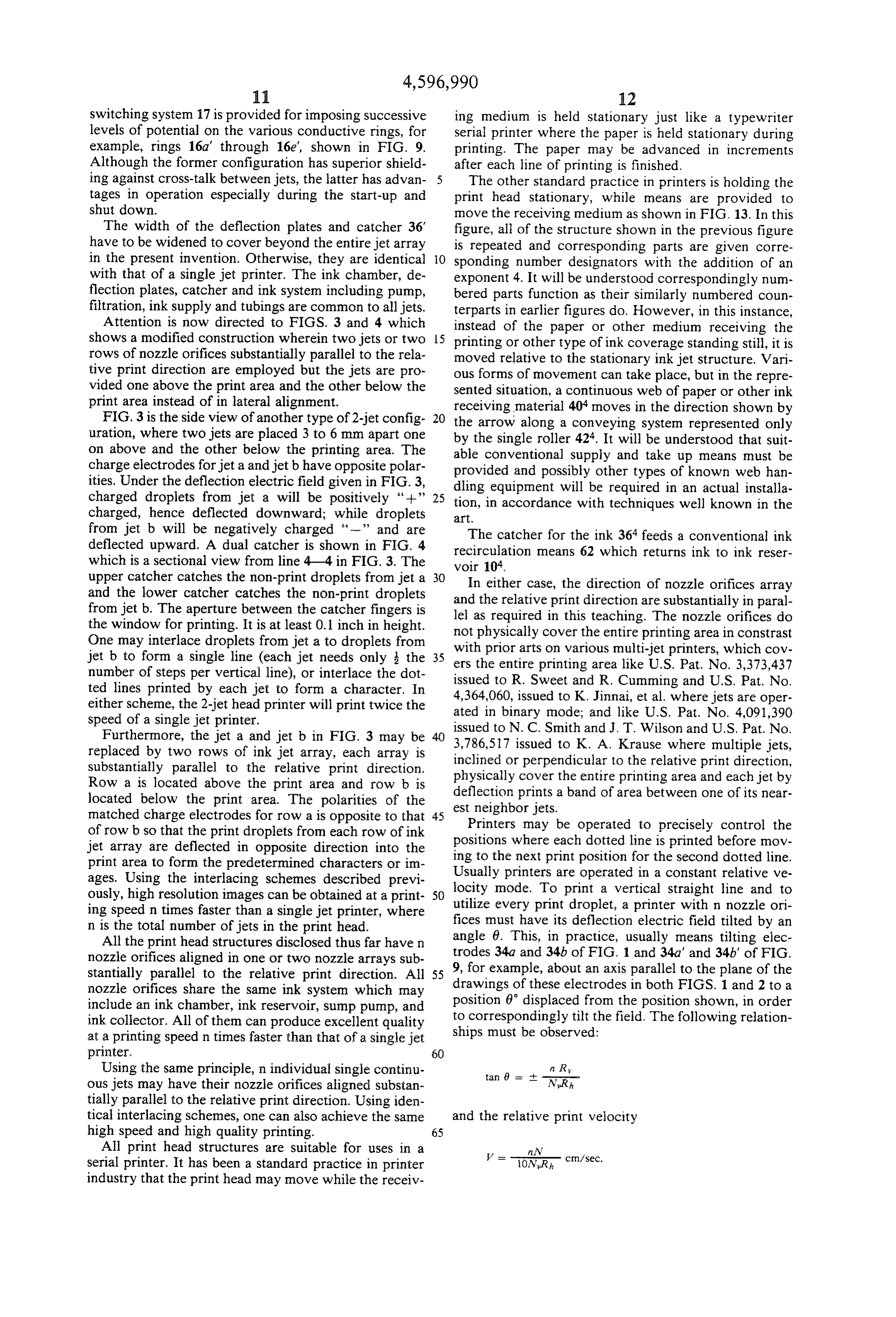
All the print head structures disclosed thus far have n trodes nozzle orifices aligned in one or two nozzle arrays sub 34a and 34b of FIG. 1 and 34a' and 34b' of FIG. stantially parallel to the relative print direction. All 55 9, for example, about an axis parallel to the plane of the nozzle orifices share the same ink system which may drawings of these electrodes in both FIGS. 1 and 2 to a include an ink chamber, ink reservoir, sump pump, and position 6 displaced from the position shown, in order ink collector. All of them can produce excellent quality to correspondingly tilt the field. The following relation at a printing speed n times faster than that of a single jet ships must be observed:
printer. 60
Using the same principle, n individual single continu ous jets may have their nozzle orifices aligned substan tially parallel to the relative print direction. Using iden tical interlacing schemes, one can also achieve the same and the relative print velocity high speed and high quality printing. 65
All print head structures are suitable for uses in a nN.
serial printer. It has been a standard practice in printer V = ioxir, cm/sec, industry that the print head may move while the receiv
Page 12
where 6 is the angle between the direction of deflection the deflection plates, such that the range of possible electric field and the normal of relative print direction, deflection is sufficient to permit the printing of one n is the total number of nozzle orifices in the print head, line of a predetermined width on receiving medium N is the total number of available print droplets gener in one sweep across the printing band, ated per second per jet, Ny is the number of vertical 5 voltage switching means applying selected voltage in print positions available per nozzle orifice, and Rh, Ry a prearranged order to each charging electrode as are horizontal and vertical resolutions in dots/mm., individual droplets break off from the ink filament respectively. The “--' and "-' signs depend on the adjacent the charging electrode to induce a charge direction of relative movement and the sequence of of predetermined magnitude on each droplet caus droplet printing either from top to bottom or visa versa. O ing each droplet to follow a particular path to a The relationship can also be visualized from FIG. 11, predetermined position within each line on the the diagram which schematically illustrates the range of receiving medium, distribution of ink droplets by the electrostatic field in a ink collector means positioned for collection of non line along a relatively moving receiving surface at a printink droplets for all jets generated by a particu constant speed. In order to print the lines normal to the 15 lar level of voltage, and direction of movement and the physical alignment of means for supporting the receiving medium and said the orifice nozzles, the field must be tilted; otherwise, array of nozzle orifices for relative movement in a the lines will be tilted at an angle-6 to normal which is direction substantially parallel to said axis of said determined by relative speed of movement. Correction array of nozzle orifices so that by relative move is accomplished by tilting the deflection field by the 20 ment a band is covered on the receiving medium in angle 6. When the printer is operating in a constant which all print positions within the band are able to velocity mode, such correction will allow the line to be be filled by lines each drawn by a single nozzle normal to the direction of movement. In a five jet orifice such that the lines drawn by all of the nozzle printer, as shown in FIGS. 9 and 11, the resolution is orifices are interlaced within the band. 240 dots per inch both in the vertical and horizontal 25 2. The multi-inkjet printer of claim 1 in which the directions. Hence, n/Rh=5, N/Ry=32 and tan nozzle orifices and related structure are stationary and 6s, 0.15625 or 6s 8.88. the means supporting the receiving medium is movable The invention as described above suggests only a few relative thereto. m of its possible embodiments. While some variations and 3. The multi-inkjet printer of claim 1 in which the modifications have been described, it will be clear to 30 nozzle orifices and related structure are on a carriage those skilled in the art that many more exist. All varia movable relative to the means supporting the receiving tions, modifications and embodiments of the invention medium, and means for advancing the receiving me with the scope of the claims are intended to be within dium in increments of predetermined width. the scope and spirit of the present invention. 4. The inkjet printer of claim 1 in which the ink I claim: 35 collector means is connected by recirculation means 1. A multi-ink jet printer providing interlacing of back to the ink chamber.
print lines to provide a band of printing across a receiv 5. The inkjet printer of claim 1 in which electrostatic ing medium comprising: means is interposed between adjacent charging elec an ink chamber and an array of nozzle orifices gener trodes to isolate charge effects imposed on droplets of ally aligned on an axis substantially parallel to the one stream from droplets of another.
relative print direction, 6. The inkjet printer of claim 1 in which the means to means to apply pressure to the ink chamber to force apply pressure to the reservoir to force ink out through ink out through each of said nozzle orifices in a thin the orifices is constant pressure or constant flow means filament, including means acting on the ink to and the means acting on the ink to break the filaments break the filament into droplets of predetermined 45 into droplets is an acoustic wave generator positioned size, each droplet producing a dot of predeter relative to the ink chamber and nozzle orifices to gener mined size in a raster of dots forming a printed ate acoustic waves of the same amplitude and the same character, phase.
deflection plates between which all of the droplets 7. The inkjet printer of claim 1 in which the means to pass in droplet paths from the respective nozzle 50 apply pressure to the reservoir includes means for recir orifices each in paths transverse to an electrostatic culating ink from the ink collector means and applying field created by the deflection plates, constant pressure or constant flow characteristics to the deflection voltage supply means connected to the ink and the means acting on the ink to break the filament deflection plates to impose an electrostatic field into droplets includes a plurality of acoustic wave gen between the deflection plates, 55 erating means positioned relative to the ink chamber charging electrode means fixed relative to each noz and the nozzle orifices such that acoustic waves gener zle orifice in position adjacent to the breaking point ated are of the same amplitude and the same phase. of ink filament associated with the respective noz 8. The inkjet printer of claim 1 in which a plurality of zle orifices along the droplet paths from that noz charge rings are molded in a single insulating block and zle, conductive members are placed between the charge a source of voltage connected to the respective electrodes and are grounded electrically to afford elec charging electrodes means each of which in turn is trostatic shielding to isolate charge effects imposed on capable of inducing electrostatic charge on the droplets of one stream of droplets of another. individual droplets as they break off from the fila 9. The inkjet printer of claim 1 in which the charging ment emerged from the nozzle orifice associated 65 electrode means are supported in common insulating with the charging electrode, causing the droplets Structure.
to be deflected into paths determined by their 10. The inkjet printer of claim 9 in which the charg charge as they pass through the field imposed by ing electrode means are each ring-shaped, U-shaped, or
Page 13
semicircular shaped, and each charging electrode is 14. An inkjet printer for printing along a band onto a precision-formed to be identical to one another. relatively moving receiving medium comprising: 11. A multi-ink jet printer providing interlacing of an ink chamber having at least two matched orifice dotted lines in a matrix print format for marking a re nozzles so that one orifice is positioned beyond one ceiving medium comprising: edge of the band of printing and the other orifice is an array of nozzle orifices aligned along an axis and positioned beyond the other edge of the band, connected to an ink source, means to apply pressure to the ink chamber to force means to apply pressure to the ink source to force ink ink out through each of said orifice nozzles in a thin out through each of said nozzle orifices in a thin filament, including means acting on the ink to filament, including means acting on the ink to O break the filament into droplets of predetermined break the filament into droplets of predetermined size, each droplet capable of producing a dot of size, droplets issuing from a respective one of said predetermined size in a raster of dots forming the nozzle orifices capable of producing one of the printing within the band, dotted columns in the matrix print format, deflection plates between which all of the droplets means for establishing an electrostatic field having a 15 pass in droplet paths from the respective orifice direction substantially perpendicular to said axis of nozzles each in paths transverse to the deflection said array of nozzle orifices through which all of plates, said droplets pass, each droplet path being trans deflection voltage supply means connected to the verse to the direction of the electrostatic field, deflection plates to impose and electrostatic field charging electrode means positioned adjacent to each 20 between the deflection plates, nozzle orifice for individually charging said drop charging electrode means fixed relative to each ori lets, fice nozzle in position adjacent to the respe tie a signal source connected to said charging electrode orifice nozzles along the droplet paths from that for selectively inducing electrostatic charges on nozzle, said individual droplets as they break off, causing 25 a source of voltage connected to the respective them to be deflected into paths determined by their charging electrode means each of which in turn is charge level as they pass through said electrostatic capable of inducing electrostatic charge on the field, such that the range of possible deflection is individual droplets as each droplet breaks off from sufficient to permit the printing of a matrix print the filament emerged from the orifice nozzle asso format of a predetermined height on the receiving 30 ciated with the charging electrode, causing the medium, droplets to be deflected into various positions switching means for switching said signal source in a within a plane transverse to the deflection plates to prearranged order to apply a selected voltage to place dots in a straight line on the receiving me each charging electrode means as individual drop dium or omit them as determined by their charge as lets break off to induce a charge of predetermined 35 they pass through the field imposed by the deflec magnitude on each droplet to cause each droplet to tion plates, imposing positive charges of predeter be directed to a predetermined position on the mined magnitude upon the stream of droplets from receiving medium whereby each dotted line of the one nozzle orifice and negative charges upon the matrix print format is marked by droplets issuing droplets from the other nozzle orifice so that the from one of said nozzle orifices only and the re 40 droplets are deflected in opposite directions, and spective dotted lines are interlaced until each ma print lines produced by each orifice nozzle are trix print format is completed, and interlaced to form separate lines defining a desired means for supporting the receiving medium and said mark, or a character, and array of nozzle orifices for relative movement in a means for supporting the receiving medium and the at direction substantially parallel to said axis of said 45 least two matched orifice nozzles for relative array of nozzle orifices. movement substantially parallel to the relative 12. An inkjet printer in a serial printer configuration print direction.
in which nozzle orifices are aligned substantially paral 15. The inkjet printer of claim 14 in which separate lel to the relative print direction and in the same plane ink collector means positioned above and below respec along which relative movement occurs between the 50 tive orifices are employed to collect the non-print ink receiving medium and the nozzle orifice array including droplets from the respective orifices. droplet charging means and deflection means, the path 16. The inkjet printer of claim 14 in which said ori of droplets produced from different nozzle orifices at fice nozzles are in two rows of inkjet nozzle orifice any given time lying in parallel planes transverse to arrays located above and below the print area, each deflection plates, such that the droplets from one nozzle 55 array of nozzle orifices aligned in an axis substantially orfice impinging receiving medium supported in their parallel to each other, the signals for the charging elec paths in one pass cover all printing positions in the line trodes having opposite polarities between the two rows and, as required, form lines of predetermined width of orifice nozzles so that print droplets from said two parallel to and interlaced with lines formed by droplets rows of orifice nozzles are deflected in opposite direc from the other nozzle orifices confined to the same 60 tion into the print area and are interlaced to form a band, the width of which is determined by the deflec predetermined character or image, and means for sup tion of ink droplets, there being sufficient nozzle orifices porting the receiving medium and said arrays of nozzle to cover all lines including all print positions in the orifices for relative movement in a direction substan band. tially parallel to the axis of said arrays of nozzle orifices. 13. The inkjet printer of claim 12 in which the spac 65 17. The method of printing with a multi-ink jet ing of the nozzle orifices and the timing of the relative printer to accomplish proper line interlace within a motion are such that lines drawn by droplets from the given character where the printer has an array of noz respective orifices are interlaced with one another. zles parallel to the relative print direction, means for
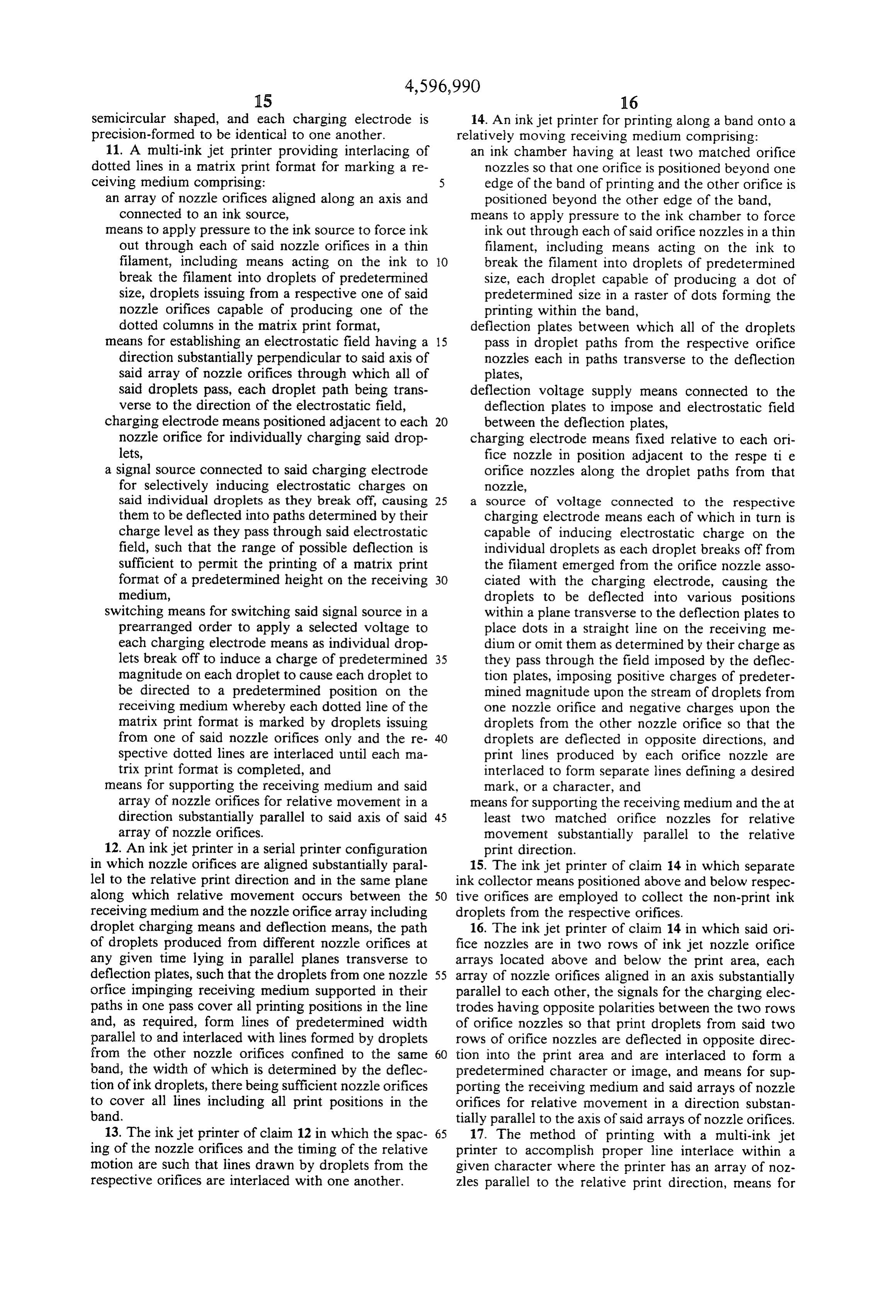
Page 14
generating sequentially timed droplets from the nozzles, millimeter, and repeating the process along each individual means for each nozzle for omitting or impos line of characters.
ing different charges upon the droplets in accordance 19. A method of inkjet printing using two jet heads with instructions from a memory and means for deflect aligned parallel to the relative print direction compris ing droplets on which a charge has been imposed to ing generating droplets by a jet orifice structure, plac permit drawing a complete line including every se ing programmed charges on successive droplets and lected print location in that line comprising: deflecting the droplets onto a receiving medium to print generating droplets from each of the adjacent noz an nth line in a character, employing a second jet to zles, print the (n+1)th line, by the same process, after a charging each droplet in accordance with selected 10 timed delay of (D-E1/R)/10V seconds or a spacial character patterns of characters selected from delay of (RD-1) dotted lines, where resolution is R memory, imposing a uniform field for the array to deflect ters dots per millimeter, D represents spacing between cen charged droplets to draw parallel lines or partial relative of adjacent nozzles in millimeters, and V is the lines needed for selected characters transverse to 15 printing velocity in cm/sec. 20. A method of inkjet printing using two jet heads the direction of relative movement to provide a aligned substantially parallel to the relative print direc band of printing, such that the kth jet of an in jet tion comprising generating array will print every (minck)th line where m is an droplets by a jet orifice integer, and structure, placing programmed charges on successive timing delay between the droplet line patterns for 20 droplets and deflecting the droplets onto a receiving adjacent nozzles to (D-El/R)10V seconds where R medium to print at the 202n)th line in a character, em is the resolution defined in dots per millimeter and ploying a second jet to print the 202n+1)th line, by the D is the spacing in millimeters between adjacent same process, after a timed delay of (D-2/R)/10V nozzles and "V" is the relative print speed in seconds or a spacial delay of (DR2) dotted lines, cm/sec. so that interlaced lines properly complete 25 where resolutions is R dots per millimeter, Drepresents the selected characters. spacing between centers of adjacent nozzles in millime 18. The method of printing with a multi-ink jet ters, and V is the relative print velocity in cm/sec. printer having an array of nozzles parallel to the relative 21. A multi-inkjet printer of claims 1, 11, 12, 14, or 16 print direction, means for generating sequentially timed containing n nozzles orifices aligned in one or two ar droplets from the nozzles, individual means for each 30 rays with axis (or axes) substantially parallel to the nozzle for omitting or imposing different charges upon relative print direction, printing in a constant relative the droplets in accordance with instructions from a print velocity mode, the deflection electric field must be memory and means for deflecting droplets on which a tilted by an angle 6, statisfying the following relation charge has been imposed to permit drawing a complete ships:
line including every selected print position in that line 35 comprising:
generating droplets from each of the adjacent noz -- in R
zles, charging each droplet in accordance with selected and the relative print velocity character patterns of characters selected from 40 memory, imposing a uniform field for the array to deflect cm/sec, charged droplets to draw parallel lines or partial lines needed for selected characters transverse to the direction of relative movement to provide a 45 where 0 is the angle between the direction of deflection band of printing, such that the kth jet of an in jet electric field and the normal of relative print direction, array will print every (minck)th line where m is an n is the number of nozzle orifices in the print head, Nis integer, and the total number of possible print droplets generated per subjecting droplets generated from a lagging adjacent orifice per second, N is the number of possible print jet to form adjacent interlaced lines in a character 50 positions available in the vertical direction, and Ry and to a spacial delay of (DR-1) dotted lines wherein Rh are resolutions in dots/mm. in the vertical and horia D is the spacing between centers of adjacent noz Zontal directions, respectively.
zles in millimeters and R is resolution in dots per
Page 15
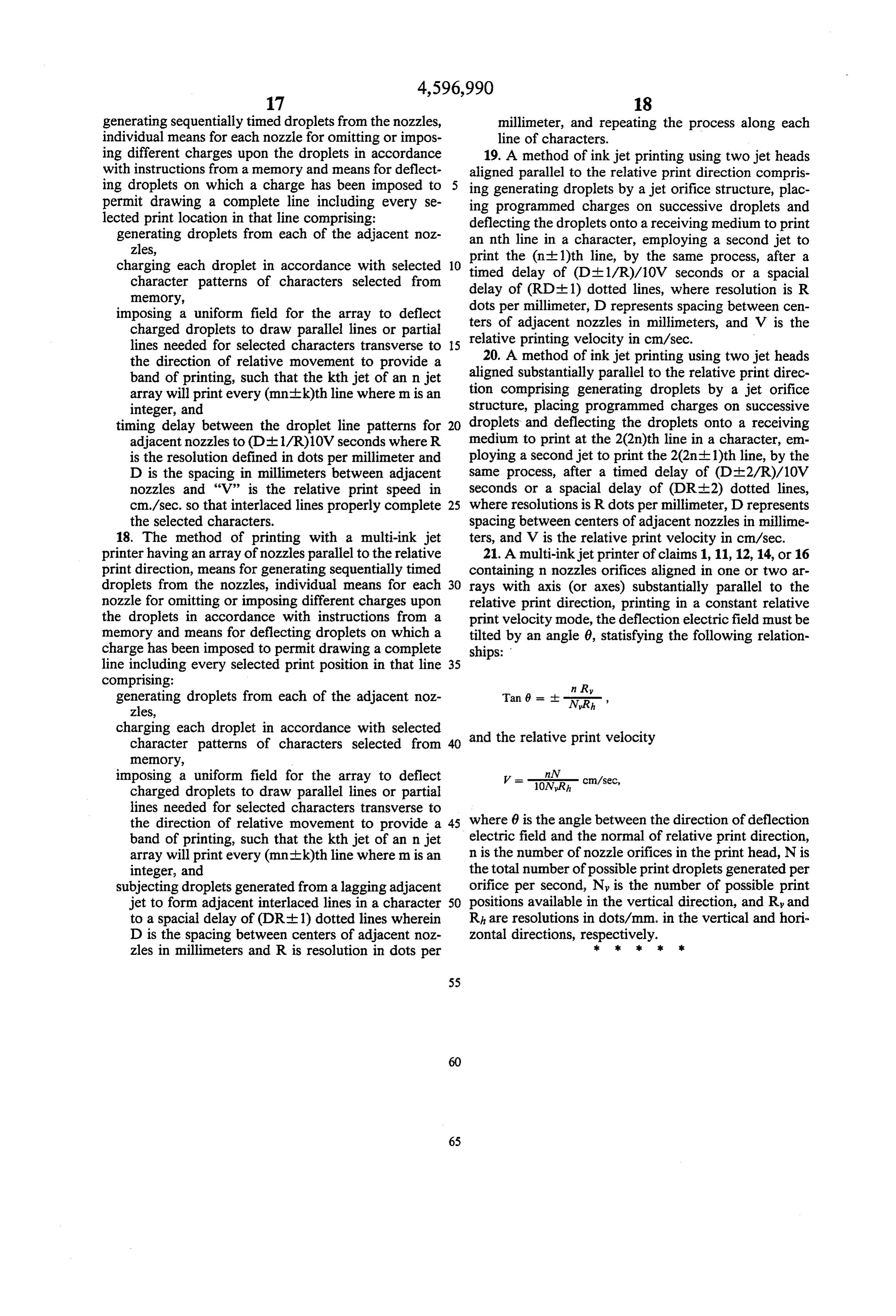
UNITED STATES PATENT AND TRADEMARK OFFICE
CERTIFICATE OF CORRECTION
NVENTOR(S) : Shou. L. Hou it is Certified that error appears in the above-identified patent and that said Letters Patent is hereby Corrected as shown below
Column 8, line 38, delete " (2n + l)th" and insert
Column 9 line 64, delete "th" and insert --the-- Column l2, line 33, delete "constrast" and insert
Claim l4, column l6, line l9, delete "and" and insert --an--;
Claim l4, column l6, line 22, delete "respe ti e" and insert --respective -- ;
Claim 2l, column l8, line 29, delete "nozzles" and insert --nozzle --.
Signed and Sealed this
Twenty-fourth Day of March, 1987
Attest:
DONALD J. QUIGG
Attesting Officer Commissioner of Patents and Trademarks
Page 16
UNITED STATES PATENT AND TRADEMARK OFFICE
CERTIFICATE OF CORRECTION
INVENTOR(S) : Shou. L. Hou
It is Certified that error appears in the above-identified patent and that said Letters Patent is hereby Corrected as shown below:
Column 8, line 38, delete " (2n + l)th" and insert
Column 9, line 64, delete "th" and insert --the-- ; Column l2, line 33, delete "constrast" and insert
Claim l4, column lie, line l9, delete "and" and insert --an--
Claim l4, column l6, line 22, delete "respe ti e" and insert --respective -- ;
Claim 21, column l8, line 29, delete "nozzles" and insert --nozzle --.
Signed and Sealed this
Twenty-fourth Day of March, 1987
Attest:
DONALD J. QUIGG
Attesting Officer Commissioner of Patents and Trademarks
Provenance
- Collection
- Cited prior art
- Original PDF
- patentimages.storage.googleapis.com →
- Filed
- 1984-07-02
- Pages
- 16
- Method
- pdftotext (the PDF's own text layer) + pdftoppm 300dpi page scans
- Source
- Google Patents bibliographic record
- Granted
- 1986-06-24
- Inventors
- Shou L. Hou; TMC Co
- Transcribed from
- patentimages.storage.googleapis.com →