patent · US442801
Stone-grinding wheel
16 December 1890
Page 1
(No Model.) 2 Sheets-Sheet 1,
G. B. ECKHARD T.
STONE GRINDING WHEEL.
No. 442,801. Patented Dec. 16. 1890. WZZ - A/Z. 2W242 /2, -4-ee v. 12-4244
the Noras perERs co, Phot-tuito, WASHINGroN, d. c.
Page 2
Drawing sheet — no readable text.
Page 3
UNITED STATES PATENT OFFICE.
GEORGE B. ECKHARDT, OF TOLEDO, OHIO.
STON E- G R N DNG WHEE.
SPECIFICATION forming part of Letters Patent No. 442,801, dated December 16, 1890. Application filed April 14, 1890, Serial No. 347,915. (No model.)
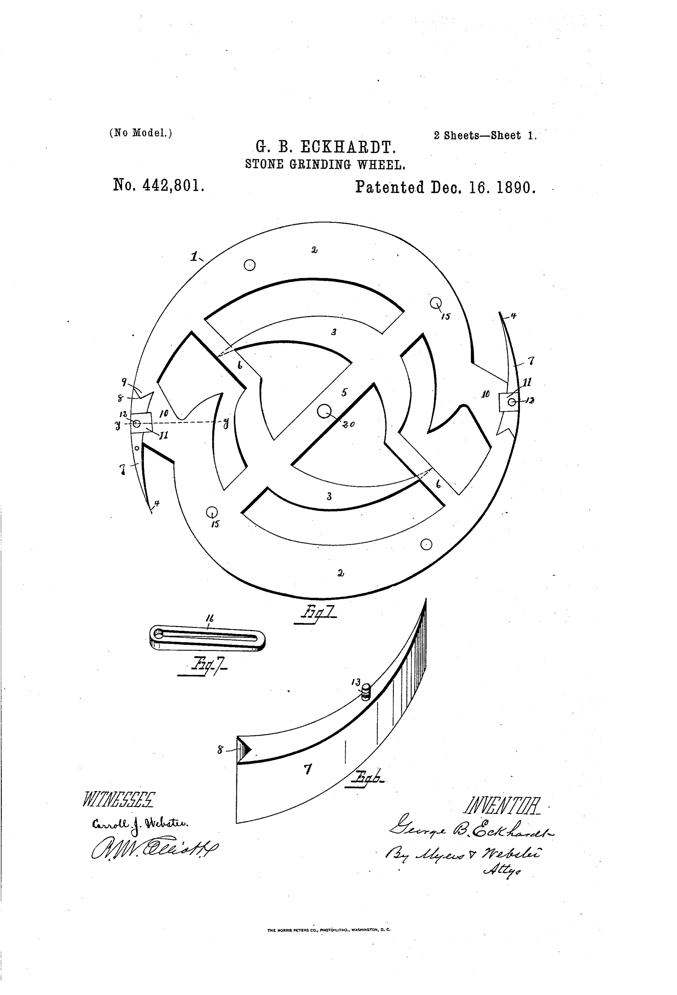
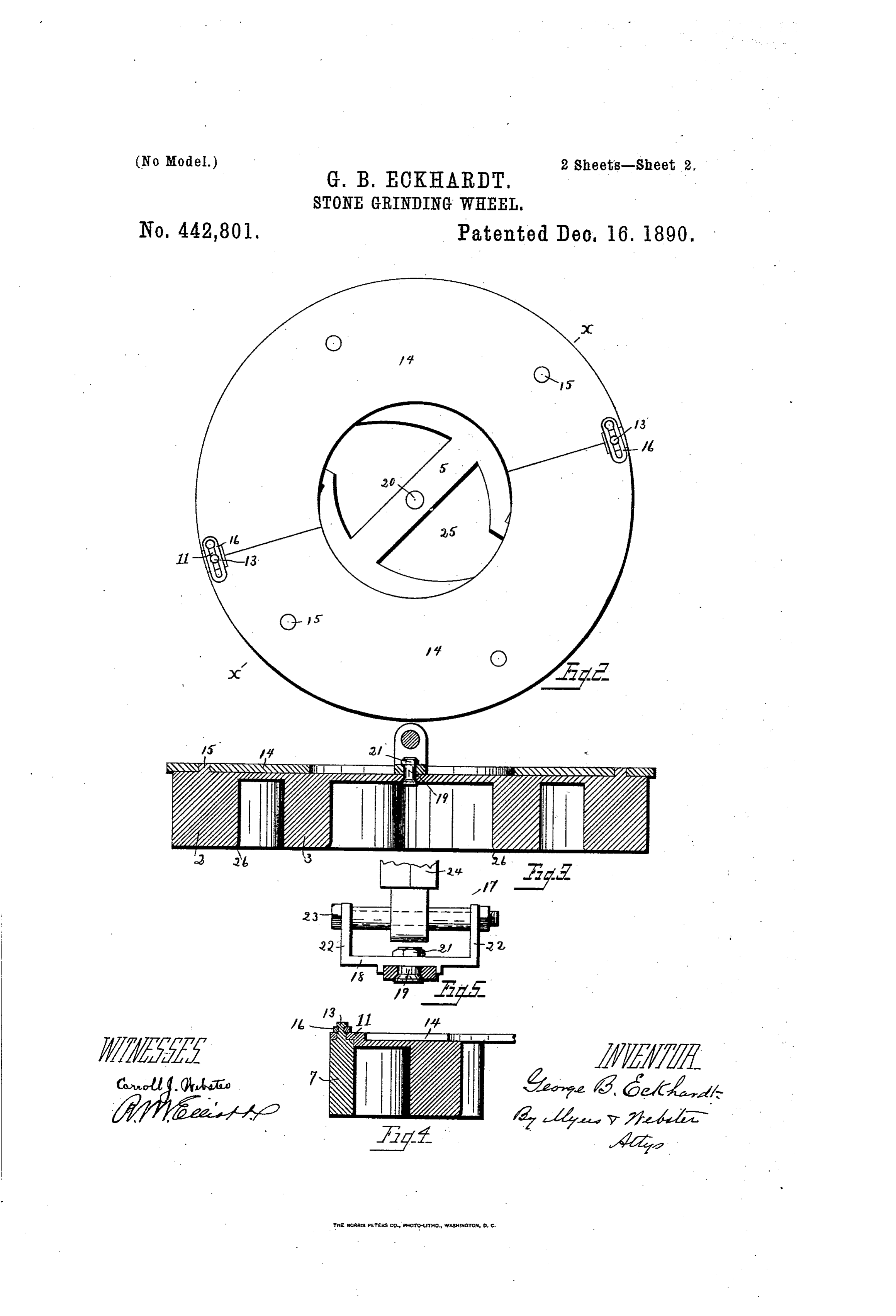
To all whon it inctly concern tion, illustrated in the drawings, and more Be it known that I, GEORGE B.ECKHARDT, particularly pointed out in the claims. a citizen of the United States, residing at To In the accompanying drawings, forming ledo, in the county of Lucas and State of Ohio, part of this specification, and in which like 55 5 have invented certain new and useful Im numerals of reference indicate corresponding provements in Stone-Grinding Wheels; and I parts, I have illustrated one form of device do hereby declare that the following is a full, embodying the essential features of my in clear, and exact description of the invention, vention, although the same may be carried which will enable others skilled in the art to into effect in other ways without in the least O which it appertains to make and use the same, departing from the spirit thereof, and in these reference being had to the accompanying drawings drawings, and to the figures of reference Figure 1 is a top plan view of my improved marked thereon, which form part of this speci grinding-wheel, showing its peculiar construc fication. tion. Fig. 2 is a similar view showing the My invention relates to improvements in cover in place upon the wheel. Fig. 3 is a Wheels for grinding or polishing stone. vertical sectional view taken on the line aca Heretofore grinding-wheels have been gen of Fig. 2, showing more particularly the rela erally constructed of a series of concentric tion between the cover and wheel. Fig. 4 is rings secured to a suitable backing provided a similar view taken on the line y if of Fig. 1, 7 o With an opening through which the material showing the manner of holding the cover used to grind down the stone is fed. It has upen the wheel. Fig. 5 is an enlarged detail been found in practice that the best cutting view showing the form of hanger for connect result of the material cannot be obtained for ing with the wheel, the actuating shaft being the reason that it would not be changed be broken off. Fig. 6 is a perspective detail view 75 25 tween the rings so as to present a fresh sur of a removable point used on this wheel, and face to the stone as the wheel was operated, Fig. 7 is a perspective detail view of the as that part nearest the center would be but wedge-shaped key for holding the cover in slightly agitated or changed, thereby leaving place upon the wheel.
the work to be done by the material confined Referring to the drawings, 1 designates the between the rings farthest removed from the wheel, which may be constructed of any center. It is the object of the invention to metal, but preferably in this instance of iron, overcome these obstacles by producing a consisting of two outer fingers 2 and two inner grinding-wheel which shall be so arranged fingers 3. The peripheries of the fingers 2 are that the cutting material will be drawn to involute, or, more properly speaking, eccentric 3 5 ward and away from the center, whereby the with regard to the pivotal point about which said cutting material is caused to be brought the wheel revolves, while the inner sides are into contact with every part of the grinding of a like configuration, only in a less degree, wheel, thereby increasing the utility of the and terminate at 4, forming points, the func wheel and the rapidity of grinding down the tion of which will be described farther on. O StOne. The inner fingers are also eccentrically With these objects in view the invention arranged. The fingers are connected and consists, broadly, of a grinding - wheel con braced by means of plates 5 and 6, which are structed with a series of fingers arranged in of sufficient thickness to give rigidity to such a manner as to exert a centripetal action the said fingers. It has been found in upon the grinding material, whereby when practice that when the wheel is made of cast the wheel is in operation there will be a con iron the points of the outer fingers crum stant circulation of a grinding material to the ble when in use, from the fact that, being Center. thinner than the remaining portion of the The invention further consists in the wa finger, they become chilled sooner, and are Co rious novel details of construction, as will be consequently brittle and apt to break and hereinafter fully described in the specifica cannot be sharpened when they have become
Page 4
dulled. In order to overcome these obstacles, can work its way between the grinding-faces I provide the wheel with a removable point 7, and stone the more rapid will be the Oper provided with an angular recess S, adapted ation. In order to give as large a feed as lO engage an angular point 9 on the fingers. possible, I bevel off the inner faces of each of Upon the inner ends of the fingers 2 are cast the fingers, as shown at 26, so that as the plates 10, which connect with the outer ends wheel revolves and the material strikes the of the fingers, as shown, and against which inclined faces just referred to it will paSS un the points abut. The plates 10 also carry der the wheel more rapidly than Were a 55 lugs or projections 11, provided with aper straight wall presented, as with wheels of or O tures 12, through which extend studs 13 upon dinary construction. the point. The cover 14 is constructed, pref Having thus fully described my invention, erably, of two Semicircular pieces, which are what I claim as new, and desire to secure by provided with apertures adapted to engage up Letters Patent, is
Wardly - extending projections 15 upon the 1. A grinding-wheel provided with eccen Wheels to hold the said cover from unoving. In trically-disposed fingers and plates connect Order to lock the covers and the points securely ing said fingers, as set forth. in place, wedge-shaped slotted keys 16 are en 2. A grinding-wheel constructed with a se ployed which engage with the studs 13 of the ries of eccentrically-arranged fingers and re points, so that by driving the wedges in the movable points carried by the outer series of points are drawn up against the covers, thus fingers.
Securely clamping the two parts together. 3. A grinding-wheel constructed of a series The coupling 17 for communicating with of eccentrically-arranged fingers, the outer of the motion-imparting mechanism consists of the said series being provided with remov a base 18, provided with an aperture adapted able points, a cover adapted to fit on said 25 to receive a bolt 19, which extends through wheel, and means for clamping wheel and an opening 20 in the wheel, and nut 21, serv cover together.
ing to clamp the base and wheel securely to 4. The combination of a grinding-wheelcon gether. At each end the base is provided structed of a series of fingers provided with 75 with an upwardly-extending fange 22, through removable points, studs carried by the said which extends a bolt 23 for clamping the fingers and points, a cover adapted to fit on lower end on the shaft 24 in place, which shaft the said wheel and having apertures adapted communicates with a motion-in parting mech to engage the said studs, and a wedge-shaped anism. key adapted to engage the studs on the points In operation the wheel is revolved in the to clamp the said points and coversecurely in 35 ordinary manner, and the cutting material, place.
which may be chilled shot, sand, or einery, 5. A grinding-wheel constructed with a se is fed to the interior of the wheel through the ries of fingers arranged substantially eccen space 25. As the wheel revolves, the cutting tric to its pivotal point and having the inner 85 material will work its way under the lower faces of each of the fingers beveled off at the part of the wheel until it strikes the points, point at which it contacts with the stone. when they will act as gatherei's to drive the In testimony that I claim the foregoing as material back to the center of the wheel again, my own I hereby affix my signature in pres from which point it works its way out in the ence of two witnesses.
manner just described. As the utility of this GEORGE B. ECKHARDT. 45 device depends largely upon the rapidity Witnesses:
with which it can grind away stone, it follows R. W. ELLIOTT, that the greater the amount of material that WILLIAM WEBSTER.
Provenance
- Collection
- Cited prior art
- Original PDF
- patentimages.storage.googleapis.com →
- Pages
- 4
- Method
- pdftotext (the PDF's own text layer) + pdftoppm 300dpi page scans
- Source
- Google Patents bibliographic record
- Granted
- 1890-12-16
- Transcribed from
- patentimages.storage.googleapis.com →