patent · US4242200
Filters for purifying fluids containing ferromagnetic particles
30 December 1980
Page 1 — bibliographic record
United States Patent 19 11 4,242,200 Dubourg 45 Dec. 30, 1980
(3) ESSESSEEPs FOREIGN PATENT DOCUMENTS PARTICLES 2909017 9/1979 Fed. Rep. of Germany ........... 210/223
75 Inventor: Michel Dubourg, Le Mesnil Saint 204324 9/1970 United Kingdom - ... 210/222 Denis, France Primary Examiner-Theodore A. Granger o Attorney, Agent, or Firm-Haseltine, Lake & Waters 73 Assignee: Framatome, Courbevoie, France 57 ABSTRACT 21 Appl. No.: 81,092 A filter for purifying a fluid containing ferromagnetic particles, e.g. water in the primary circuit of a nuclear 22 Filed: Oct. 2, 1979 reactor using pressurized water, comprises a cylindrical envelope containing steel beads and provided with a 51 int. Cl............................................... BoD 35/06 coil for magnetizing the beads. The beads are supported 52 U.S. Cl. .................................... 20/222, 210/51,
inlopea cylindrical basket located in the cylindrical enve and the side wall of which is perforated certain
ally opposite the are arrangedzones perforated withinof the the basket basket radi side y TawV TwV wall. Fluid to be purified enters through a central drip d tube which is provided with radial perforations in zones 56) References Cited radially opposite the deflectors which serve to prevent
2,398,725 4/1946 Schutte .................................. 21/223 tion.
2,452,220 10/1948 Bower ....... ... 210/222 2,607,492 8/1952 Anders ................................. 210/222 7 Claims, 4 Drawing Figures
N R
N 19
shasarasar Saarancracy
Page 2
Drawing sheet — no readable text.
Page 3
Drawing sheet — no readable text.
Page 4
Drawing sheet — no readable text.
Page 5
leaves through the other end of the filter to be recycled
FILTERS FOR PURIFYING FLUIDS CONTAINING into the primary circuit.
FERROMAGNETIC PARTICLES The disadvantages of a filter of this type are that the oxide scale tends to be deposited contantly in the same
The invention relates to improvements in filters for zones of the mass of steel beads, since the fluid circu purifying fluids containing ferromagnetic particles and lates along a constant path, and that it is difficult to more particularly for purifying the primary fluid of a restrict the circulation rate of the fluid in the bed of nuclear reactor using pressurised water. beads in order to assist filtration, and at the same time to In reactors using pressurised water, the pressurised ensure a maximum circulation rate of the fluid in the water, which constitutes the primary fluid and which 10 filter in order to be certain of achieving effective filtra comes into contact with the fuel rods before being sent tion.
into the steam generators in order to heat and vaporise Furthermore, if it is desired to restrict the circulation the boiler feed water or secondary fluid, becomes rate of the fluid in the filter and to increase the path of charged, during its circulation in the reactor and in the 15 the passage through the mass of beads, it may be neces steam generators, with iron oxide particles formed dur sary to increase the size of the filter to such an extent ing the prolonged contact of the water with certain thatAccording its bulk and its cost become prohibitive. to the invention there is provided a filter steel parts of the nuclear reactor. for purifying a fluid containing ferromagnetic particles, It is very important to remove these oxide particles said filter comprising:
from the primary fluid by means of a filter, in order to prevent the amount of oxide in the primary fluid from 20 to aancylindrical envelope having an inlet for connection inlet pipe for the fluid to be purified and an outlet becoming excessive and to prevent these particles from for connection to an outlet pipe for the purified fluid; becoming activated after having resided in the core and ferromagnetic beads within said envelope and be then being deposited on the primary piping, making a tween significant contribution to the activity and to the con 25 a coilwhich the fluid will, in use, pass surrounding said cylindrical envelope for con tamination of the surfaces. nection to electric current supply means to produce a The particles trapped by the filter can no longer cir magnetic culate in the primary circuit and the probability of con beads will,field for magnetising said beads so that said tamination of the operating and maintenance personnel veyed by the fluid; retain ferromagnetic particles con in use, is thus reduced; the personnel can therefore remain near 30 an unclogging circuit communicating with the inte the reactor installations for a longer time without suffer rior of said envelope;
ing excessive irradiation. a cylindrical basket for supporting said beads, ar This purification of the primary fluid most of course ranged within said envelope and coaxial with said enve be carried out while the reactor is in operation in order lope, said basket being provided with perforations al to ensure continuous purification of the pressurised 35 lowing the interior of said basket containing said steel Water, beads to communicate with the space between said However problems arise from the fact that this filtra envelope and said basket and into which said outlet tion must be effected on pressurised water at high tem opens said perforations being provided in zones of the perature. side wall of said basket and at the ends of said basket; In order to effect this purification, it has been pro deflectors, arranged within said basket and having posed to use an electromagnetic filter comprising a solid walls spaced inwardly of said side wall of said cylindrical envelope filled with beads of a ferromag basket, and extending over a certain length in the axial netic material, particularly steel beads, which is sub direction, in that zone of said basket in which said beads jected to a magnetisation cycle so that the beads will are located; and retain the ferromagnetic particles conveyed by the pri 45 a central tube which is connected at one and to said mary fluid. inlet and is closed at its other end, and which is directed An electromagnetic filter of this type, which com along the axis of said filter and arranged in the bed of prises a coil surrounding the envelope in which the beads in a central part of said basket, said tube having beads are located, in order to create a magnetic field radially directed lateral perforations for placing the capable of magnetising the beads, is generally arranged 50 interior of said tube in communication with the interior in parallel with a primary pump used for the circulation of said basket in the zones of said tube which are located of the pressurised water. radially opposite said deflectors, said deflectors being The interior of the cylindrical envelope containing arranged opposite said perforated zones of said side wall the beads also communicates with an unclogging circuit of said basket, which zones are located radially opposite which is independent of the primary fluid circuit and 55 said perforations in said central tube, in order to prevent enables periodic removal of the oxide particles retained fluid from passing directly, along a solely radial path, by the beads. from said central tube to said space between said basket A proportion, which is generally of the order of a few and said envelope.
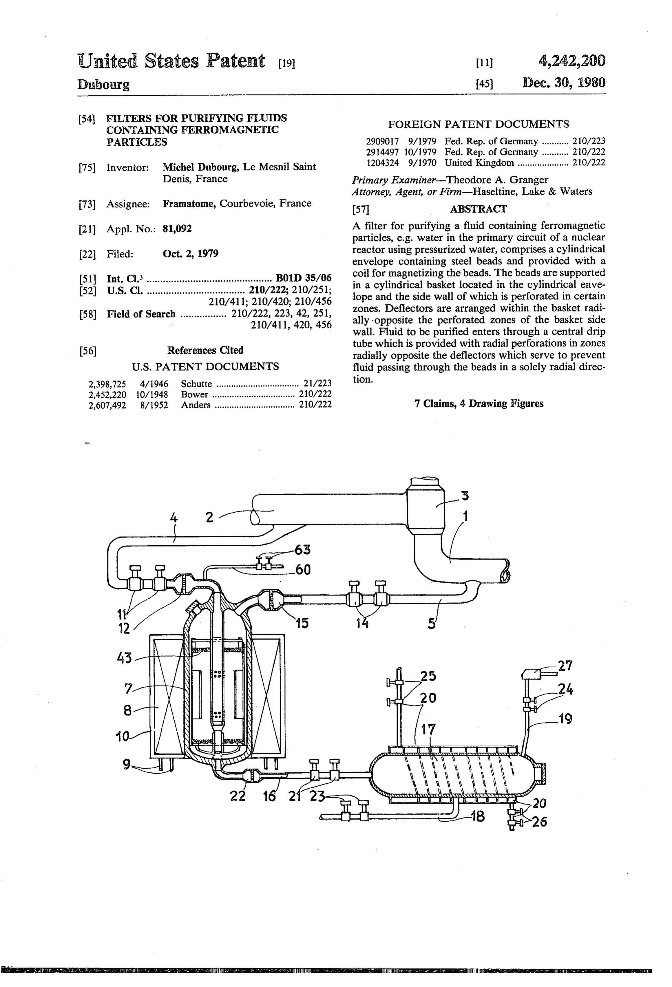
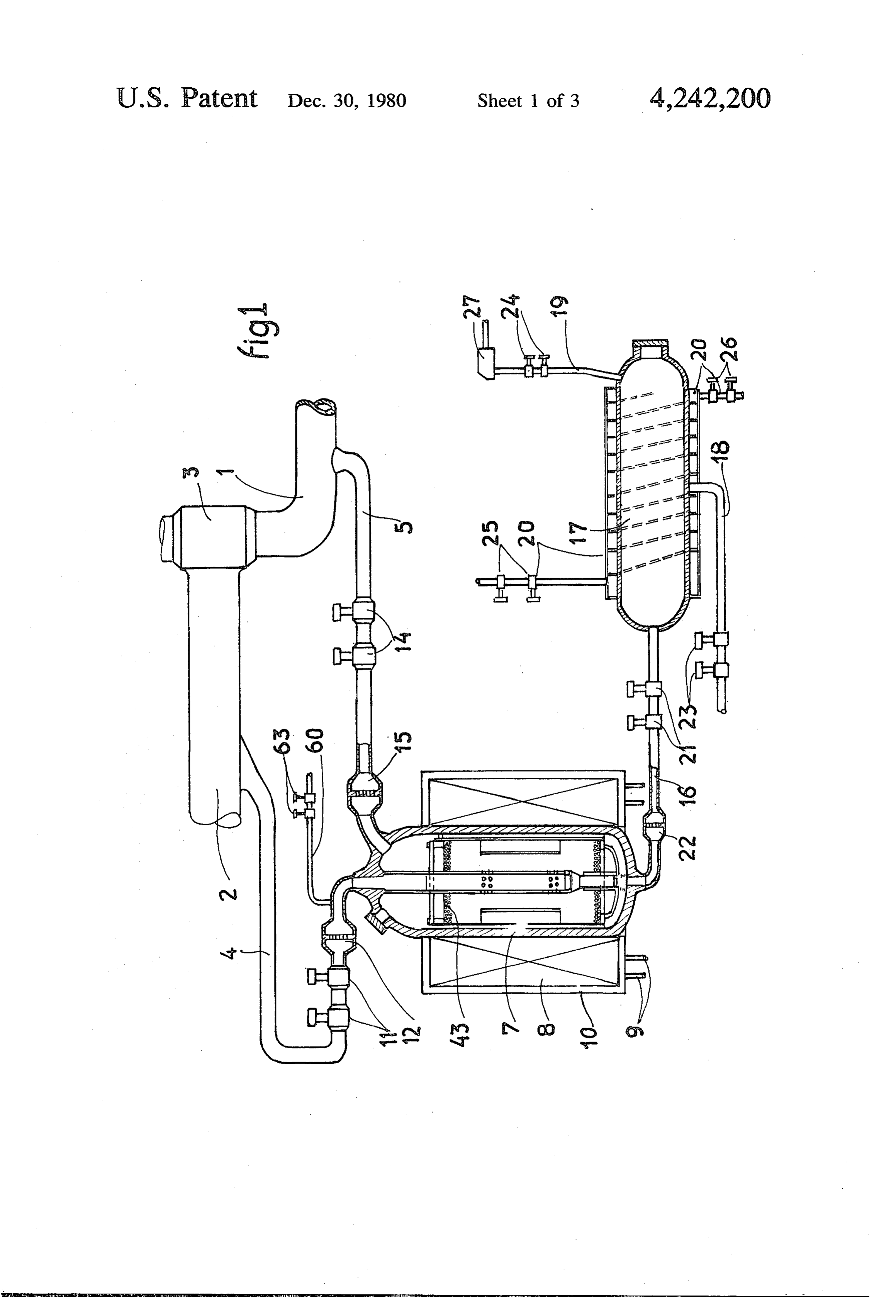
per cent, of the primary fluid flow, is diverted to the An embodiment of a filter according to the invention, filter. 60 for use in the primary circuit of a nuclear reactor using It is thus possible to purify the primary fluid continu pressurised water, either in parallel with a primary ously without thereby interfering with the circulation pump or as an off-take on the cold side of the primary of this fluid in the primary circuit and without thermal circuit, will now be described by way of example only, degradation (cooling) of the fluid, and also to unclog with reference to the accompanying drawings. the filter independently of the circulation. 65
IN THE DRAWINGS:
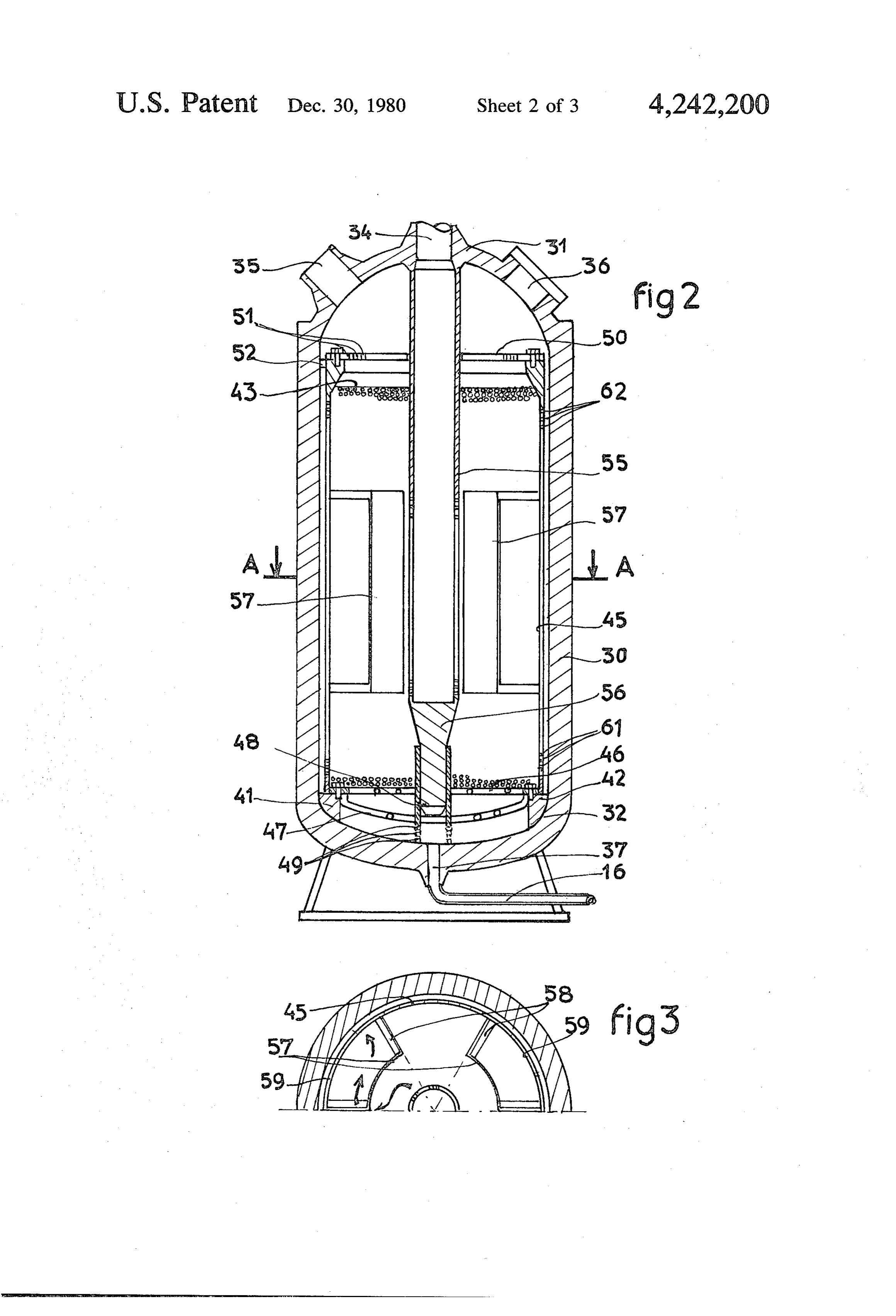
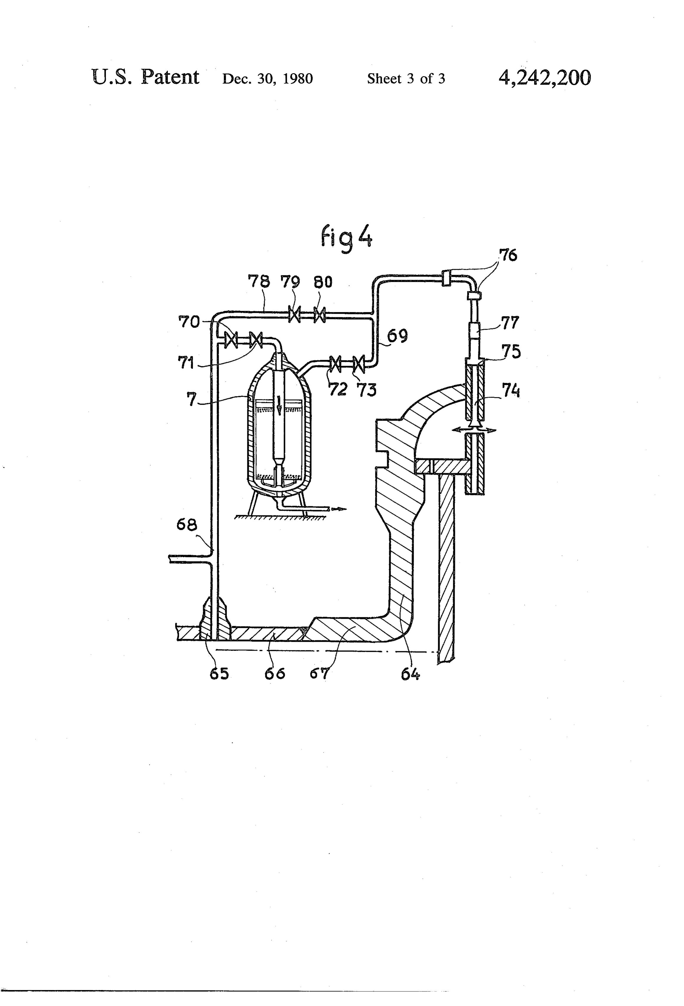
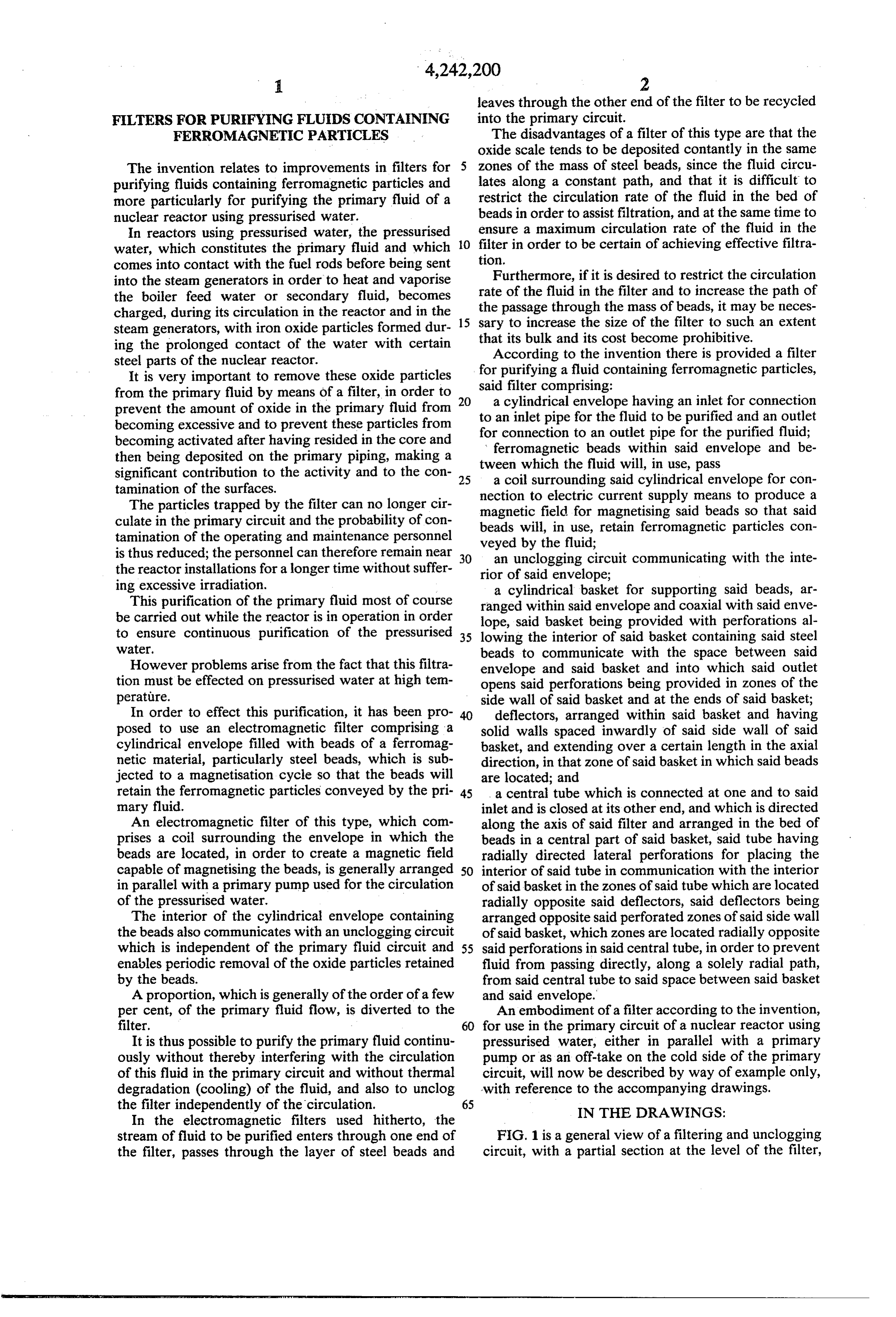
In the electromagnetic filters used hitherto, the stream of fluid to be purified enters through one end of FIG. 1 is a general view of a filtering and unclogging the filter, passes through the layer of steel beads and circuit, with a partial section at the level of the filter,
Page 6
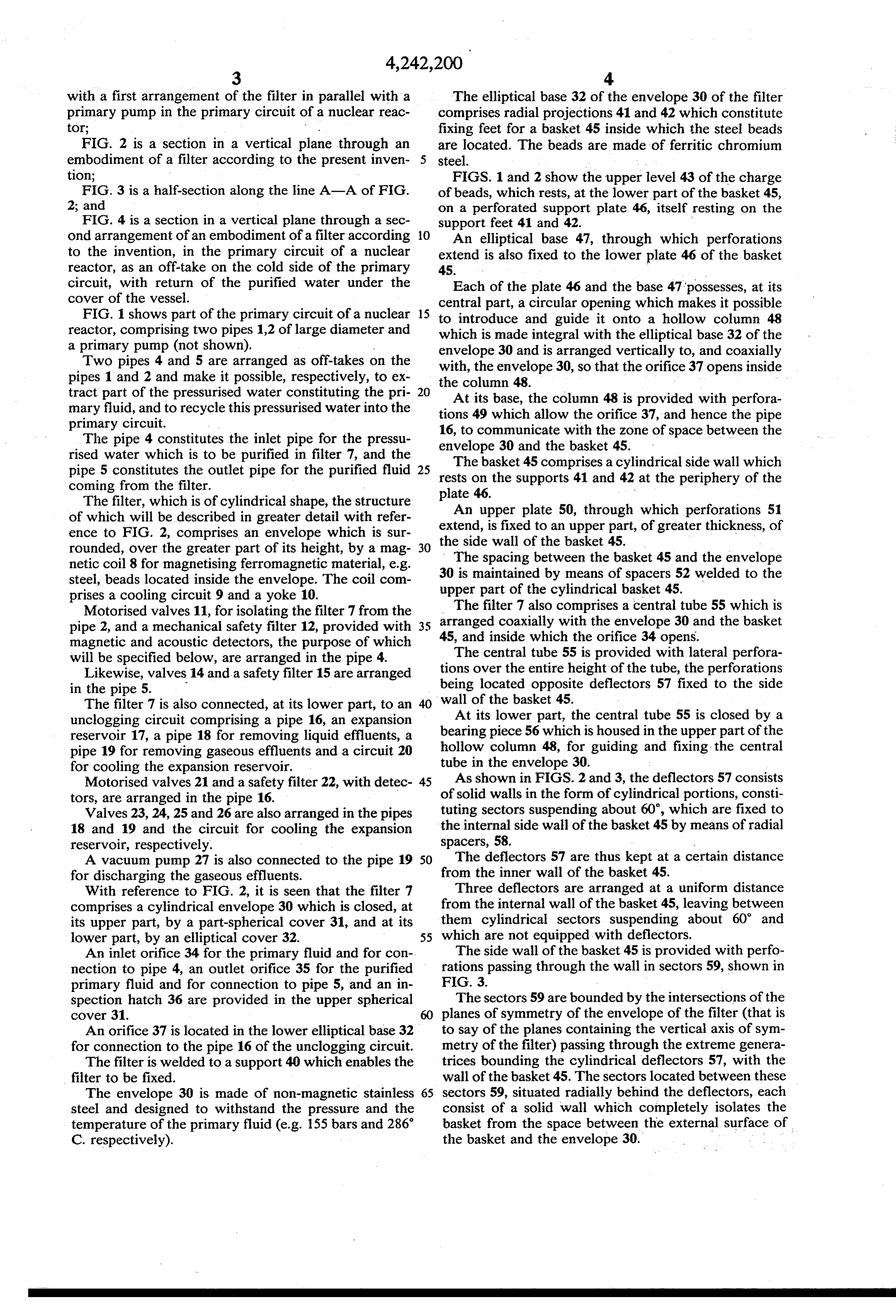
with a first arrangement of the filter in parallel with a The elliptical base 32 of the envelope 30 of the filter primary pump in the primary circuit of a nuclear reac comprises radial projections 41 and 42 which constitute tor; . fixing feet for a basket 45 inside which the steel beads FIG. 2 is a section in a vertical plane through an are located. The beads are made of ferritic chronium embodiment of a filter according to the present inven steel.
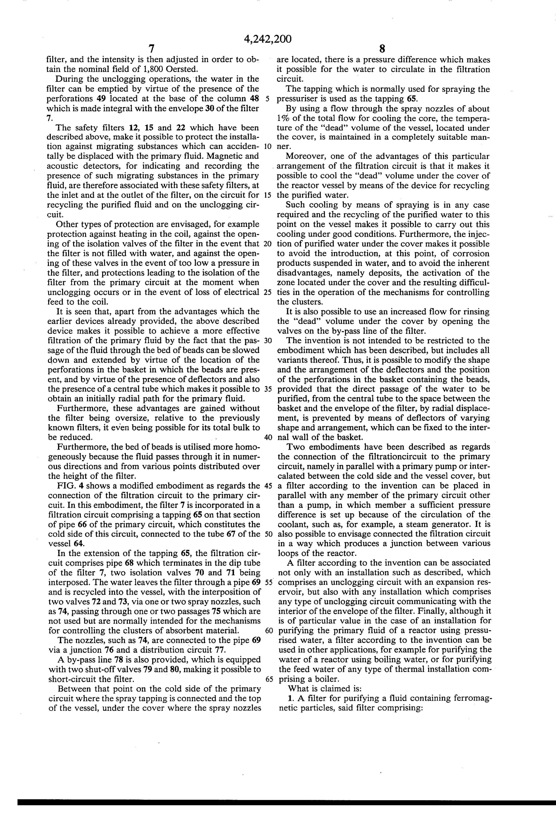
tion; FIGS. 1 and 2 show the upper level 43 of the charge FIG. 3 is a half-section along the line A-A of FIG. of beads, which rests, at the lower part of the basket 45, 2; and on a perforated support plate 46, itself resting on the FIG. 4 is a section in a vertical plane through a sec support feet 41 and 42.
ond arrangement of an embodiment of a filter according 10 An elliptical base 47, through which perforations to the invention, in the primary circuit of a nuclear extend is also fixed to the lower plate 46 of the basket reactor, as an off-take on the cold side of the primary 45.
circuit, with return of the purified water under the Each of the plate 46 and the base 47 possesses, at its cover of the vessel. central part, a circular opening which makes it possible FIG. 1 shows part of the primary circuit of a nuclear 15 to introduce and guide it onto a hollow column 48 reactor, comprising two pipes 1,2 of large diameter and which is made integral with the elliptical base 32 of the a primary pump (not shown). envelope 30 and is arranged vertically to, and coaxially Two pipes 4 and 5 are arranged as off-takes on the with, the envelope 30, so that the orifice 37 opens inside pipes 1 and 2 and make it possible, respectively, to ex the column 48.
tract part of the pressurised water constituting the pri At its base, the column 48 is provided with perfora mary fluid, and to recycle this pressurised water into the tions 49 which allow the orifice 37, and hence the pipe primary circuit. 16, to communicate with the zone of space between the The pipe 4 constitutes the inlet pipe for the pressu envelope 30 and the basket 45. rised water which is to be purified in filter 7, and the The basket 45 comprises a cylindrical side wall which pipe 5 constitutes the outlet pipe for the purified fluid rests on the supports
41 and 42 at the periphery of the coming from the filter.
The filter, which is of cylindrical shape, the structure plate 46.
An upper plate 50, through which perforations 51 of which will be described in greater detail with refer extend, ence to FIG. 2, comprises an envelope which is sur the sideiswall fixed to an upper part, of greater thickness, of of the basket 45.
rounded, over the greater part of its height, by a mag 30
The spacing between the basket 45 and the envelope netic coil 8 for magnetising ferromagnetic material, e.g.
steel, beads located inside the envelope. The coil com upper part of thebycylindrical 30 is maintained means of spacers 52 welded to the basket 45.
prises a cooling circuit 9 and a yoke 10.
Motorised valves 11, for isolating the filter 7 from the The filter 7 also comprises a central tube 55 which is pipe 2, and a mechanical safety filter 12, provided with 35 arranged coaxially with the envelope 30 and the basket magnetic and acoustic detectors, the purpose of which 45, and inside which the orifice 34 opens. will be specified below, are arranged in the pipe 4. The central tube 55 is provided with lateral perfora Likewise, valves 14 and a safety filter 15 are arranged tions over the entire height of the tube, the perforations in the pipe 5. being located opposite deflectors 57 fixed to the side The filter 7 is also connected, at its lower part, to an wall of the basket 45.
unclogging circuit comprising a pipe 16, an expansion At its lower part, the central tube 55 is closed by a reservoir 17, a pipe 18 for removing liquid effluents, a bearing piece 56 which is housed in the upper part of the pipe 19 for removing gaseous effluents and a circuit 20 hollow column 48, for guiding and fixing the central for cooling the expansion reservoir. tube in the envelope 30.
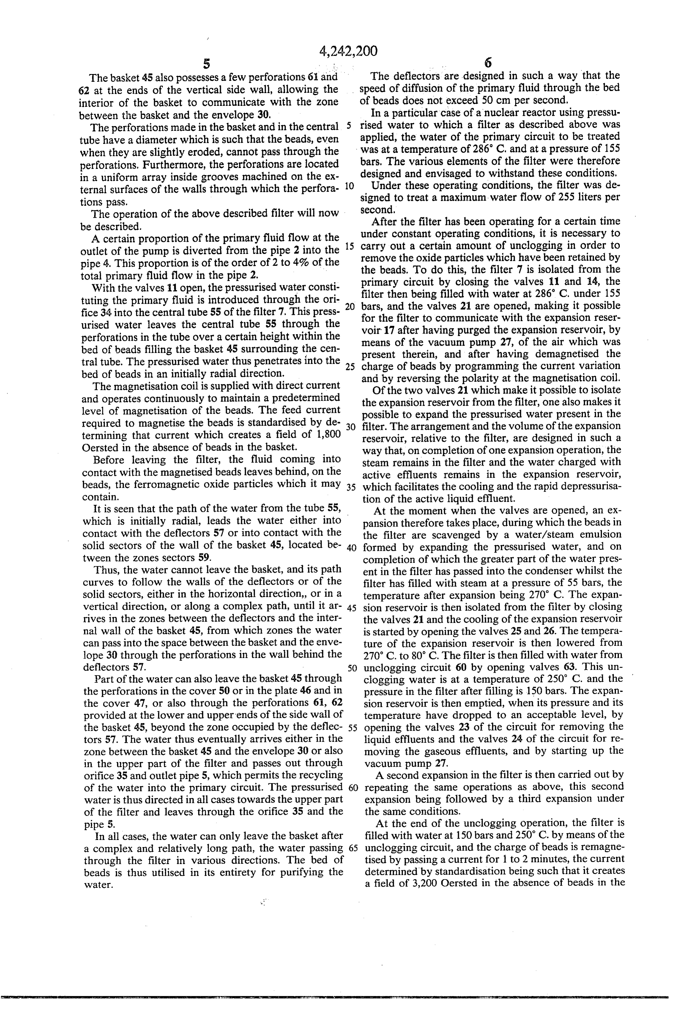
Motorised valves 21 and a safety filter 22, with detec 45 ofAs shown in FIGS. 2 and 3, the deflectors 57 consists solid walls in the form of cylindrical portions, consti tors, are arranged in the pipe 16.
Valves 23, 24, 25 and 26 are also arranged in the pipes tuting sectors suspending about 60, which are fixed to 18 and 19 and the circuit for cooling the expansion the internal side wall of the basket 45 by means of radial reservoir, respectively. spacers, 58.
A vacuum pump 27 is also connected to the pipe 19 SO The deflectors 57 are thus kept at a certain distance for discharging the gaseous effluents. from the inner wall of the basket 45. With reference to FIG. 2, it is seen that the filter 7 Three deflectors are arranged at a uniform distance comprises a cylindrical envelope 30 which is closed, at from the internal wall of the basket 45, leaving between its upper part, by a part-spherical cover 31, and at its them cylindrical sectors suspending about 60 and lower part, by an elliptical cover 32. 55 which are not equipped with deflectors. An inlet orifice 34 for the primary fluid and for con The side wall of the basket 45 is provided with perfo nection to pipe 4, an outlet orifice 35 for the purified rations passing through the wall in sectors 59, shown in primary fluid and for connection to pipe 5, and an in FIG. 3.
spection hatch 36 are provided in the upper spherical The sectors 59 are bounded by the intersections of the cover 31. planes of symmetry of the envelope of the filter (that is An orifice 37 is located in the lower elliptical base 32 to say of the planes containing the vertical axis of sym for connection to the pipe 16 of the unclogging circuit. metry of the filter) passing through the extreme genera The filter is welded to a support 40 which enables the trices bounding the cylindrical deflectors 57, with the filter to be fixed. wall of the basket 45. The sectors located between these The envelope 30 is made of non-magnetic stainless 65 sectors 59, situated radially behind the deflectors, each steel and designed to withstand the pressure and the consist of a solid wall which completely isolates the temperature of the primary fluid (e.g. 155 bars and 286 basket from the space between the external surface of C. respectively). the basket and the envelope 30.
Page 7
The basket 45 also possesses a few perforations 61 and The deflectors are designed in such a way that the 62 at the ends of the vertical side wall, allowing the speed of diffusion of the primary fluid through the bed interior of the basket to communicate with the zone of beads does not exceed 50 cm per second, between the basket and the envelope 30, In a particular case of a nuclear reactor using pressu The perforations made in the basket and in the central rised water to which a filter as described above was tube have a diameter which is such that the beads, even applied, the water of the primary circuit to be treated when they are slightly eroded, cannot pass through the was at a temperature of 286 C. and at a pressure of 155 perforations. Furthermore, the perforations are located bars, The various elemcnts of the filter were therefore in a uniform array inside grooves machined on the ex 10 designed and envisaged to withstand these conditions. ternal surfaces of the walls through which the perfora Under these operating conditions, the filter was de tions pass. signed to treat a maximum water flow of 255 liters per The operation of the above described filter will now second, After the filter has been operating for a certain time be described.
A certain proportion of the primary fluid flow at the under constant operating conditions, it is necessary to outlet of the pump is diverted from the pipe 2 into the 15 carry out a certain amount of unclogging in order to pipe 4. This proportion is of the order of 2 to 4% of the remove the oxide particles which have been retained by the beads. To do this, the filter 7 is isolated from the total primary fluid flow in the pipe 2.
With the valves 11 open, the pressurised water consti primary filter then circuit by closing the valves 11 and 14, the being filled with water at 286° C. under 155 tuting the primary fluid is introduced through the ori 20 bars, and the fice 34 into the central tube 55 of the filter 7. This press for the filter tovalves 21 are opened, making it possible urised water leaves the central tube 55 through the voir. 17 after having purged thewith communicate the expansion reser perforations in the tube over a certain height within the means of the vacuum pump 27, of the airreservoir, expansion which
was bed of beads filling the basket 45 surrounding the cen present therein, and after having demagnetised the tral tube. The pressurised water thus penetrates into the 25 charge of beads by programming the current variation bed of beads in an initially radial direction.
The magnetisation coil is supplied with direct current andOfbythereversing two the polarity at the magnetisation coil.
valves 21 which make it possible to isolate and operates continuously to maintain a predetermined the expansion reservoir from the filter, one also makes it level of magnetisation of the beads. The feed current possible to expand the pressurised water present in the required to magnetise the beads is standardised by de 30 filter. The arrangement and the volume of the expansion termining that current which creates a field of 1,800 reservoir, relative to the filter, are designed in such a Oersted in the absence of beads in the basket. way that, on completion of one expansion operation, the Before leaving the filter, the fluid coming into steam remains in the filter and the water charged with contact with the magnetised beads leaves behind, on the active effluents remains in the expansion reservoir, beads, the ferromagnetic oxide particles which it may 35 which facilitates the cooling and the rapid depressurisa contain. tion of the active liquid effluent. It is seen that the path of the water from the tube 55, At the moment when the valves are opened, an ex which is initially radial, leads the water either into pansion therefore takes place, during which the beads in contact with the deflectors 57 or into contact with the the filter are scavenged by a water/steam emulsion solid sectors of the wall of the basket 45, located be 40 formed by expanding the pressurised water, and on tween the zones sectors 59. completion of which the greater part of the water pres Thus, the water cannot leave the basket, and its path ent in the filter has passed into the condenser whilst the curves to follow the walls of the deflectors or of the filter has filled with steam at a pressure of 55 bars, the solid sectors, either in the horizontal direction, or in a temperature after expansion being 270° C. The expan vertical direction, or along a complex path, until it ar 45 sion reservoir is then isolated from the filter by closing rives in the zones between the deflectors and the inter the valves 21 and the cooling of the expansion reservoir nal wall of the basket 45, from which zones the water is started by opening the valves 25 and 26. The tempera can pass into the space between the basket and the enve ture of the expansion reservoir is then lowered from lope 30 through the perforations in the wall behind the 270° C. to 80° C. The filter is then filled with water from deflectors 57. 50 unclogging circuit 60 by opening valves 63. This un Part of the water can also leave the basket 45 through clogging water is at a temperature of 250 C. and the the perforations in the cover 50 or in the plate 46 and in pressure in the filter after filling is 150 bars. The expan the cover 47, or also through the perforations 61, 62 sion reservoir is then emptied, when its pressure and its provided at the lower and upper ends of the side wall of temperature have dropped to an acceptable level, by the basket 45, beyond the zone occupied by the deflec 55 opening the valves 23 of the circuit for removing the tors 57. The water thus eventually arrives either in the liquid effluents and the valves 24 of the circuit for re zone between the basket 45 and the envelope 30 or also moving the gaseous effluents, and by starting up the in the upper part of the filter and passes out through vacuum pump 27.
orifice 35 and outlet pipe 5, which permits the recycling A second expansion in the filter is then carried out by of the water into the primary circuit. The pressurised 60 repeating the same operations as above, this second water is thus directed in all cases towards the upper part expansion being followed by a third expansion under of the filter and leaves through the orifice 35 and the the same conditions.
pipe 5. At the end of the unclogging operation, the filter is In all cases, the water can only leave the basket after filled with water at 150 bars and 250° C. by means of the a complex and relatively long path, the water passing 65 unclogging circuit, and the charge of beads is remagne through the filter in various directions. The bed of tised by passing a current for 1 to 2 minutes, the current beads is thus utilised in its entirety for purifying the determined by standardisation being such that it creates Water. a field of 3,200 Oersted in the absence of beads in the
Page 8
filter, and the intensity is then adjusted in order to ob are located, there is a pressure difference which makes tain the nominal field of 1,800 Oersted, it possible for the water to circulate in the filtration During the unclogging operations, the water in the circuit.
filter can be emptied by virtue of the presence of the The tapping which is normally used for spraying the perforations 49 located at the base of the column 48 pressuriser is used as the tapping 65. which is made integral with the envelope 30 of the filter By using a flow through the spray nozzles of about 7. 1% of the total flow for cooling the core, the tempera The safety filters 12, 15 and 22 which have been ture of the "dead' volume of the vessel, located under described above, make it possible to protect the installa the cover, is maintained in a completely suitable man tion against migrating substances which can acciden O er.
tally be displaced with the primary fluid. Magnetic and Moreover, one of the advantages of this particular acoustic detectors, for indicating and recording the arrangement of the filtration circuit is that it makes it presence of such migrating substances in the primary possible to cool the "dead' volume under the cover of fluid, are therefore associated with these safety filters, at the reactor vessel by means of the device for recycling the inlet and at the outlet of the filter, on the circuit for 15 the purified water.
recycling the purified fluid and on the unclogging cir Such cooling by means of spraying is in any case cuit. required and the recycling of the purified water to this Other types of protection are envisaged, for example point on the vessel makes it possible to carry out this protection against heating in the coil, against the open cooling under good conditions. Furthermore, the injec ing of the isolation valves of the filter in the event that 20 tion of purified water under the cover makes it possible the filter is not filled with water, and against the open to avoid the introduction, at this point, of corrosion ing of these valves in the event of too low a pressure in products suspended in water, and to avoid the inherent the filter, and protections leading to the isolation of the disadvantages, namely deposits, the activation of the filter from the primary circuit at the moment when zone located under the cover and the resulting difficul unclogging occurs or in the event of loss of electrical 25 ties in the operation of the mechanisms for controlling feed to the coil. the clusters.
It is seen that, apart from the advantages which the It is also possible to use an increased flow for rinsing earlier devices already provided, the above described the "dead' volume under the cover by opening the device makes it possible to achieve a more effective valves on the by-pass line of the filter. filtration of the primary fluid by the fact that the pas The invention is not intended to be restricted to the sage of the fluid through the bed of beads can be slowed embodiment which has been described, but includes all down and extended by virtue of the location of the variants thereof. Thus, it is possible to modify the shape perforations in the basket in which the beads are pres and the arrangement of the deflectors and the position ent, and by virtue of the presence of deflectors and also of the perforations in the basket containing the beads, the presence of a central tube which makes it possible to 35 provided that the direct passage of the water to be obtain an initially radial path for the primary fluid. purified, from the central tube to the space between the Furthermore, these advantages are gained without basket and the envelope of the filter, by radial displace the filter being oversize, relative to the previously ment, is prevented by means of deflectors of varying known filters, it even being possible for its total bulk to shape and arrangement, which can be fixed to the inter be reduced. w nal wall of the basket.
Furthermore, the bed of beads is utilised more homo Two embodiments have been described as regards geneously because the fluid passes through it in numer the connection of the filtrationcircuit to the primary ous directions and from various points distributed over circuit, namely in parallel with a primary pump or inter the height of the filter. calated between the cold side and the vessel cover, but FIG. 4 shows a modified embodiment as regards the 45 a filter according to the invention can be placed in connection of the filtration circuit to the primary cir parallel with any member of the primary circuit other cuit. In this embodiment, the filter 7 is incorporated in a than a pump, in which member a sufficient pressure filtration circuit comprising a tapping 65 on that section difference is set up because of the circulation of the of pipe 66 of the primary circuit, which constitutes the coolant, such as, for example, a steam generator. It is cold side of this circuit, connected to the tube 67 of the 50 also possible to envisage connected the filtration circuit vessel 64. in a way which produces a junction between various In the extension of the tapping 65, the filtration cir loops of the reactor.
cuit comprises pipe 68 which terminates in the dip tube A filter according to the invention can be associated of the filter 7, two isolation valves 70 and 71 being not only with an installation such as described, which interposed. The water leaves the filter through a pipe 69 55 comprises an unclogging circuit with an expansion res and is recycled into the vessel, with the interposition of ervoir, but also with any installation which comprises two valves 72 and 73, via one or two spray nozzles, such any type of unclogging circuit communicating with the as 74, passing through one or two passages 75 which are interior of the envelope of the filter. Finally, although it not used but are normally intended for the mechanisms is of particular value in the case of an installation for for controlling the clusters of absorbent material. 60 purifying the primary fluid of a reactor using pressu The nozzles, such as 74, are connected to the pipe 69 rised water, a filter according to the invention can be via a junction 76 and a distribution circuit 77. used in other applications, for example for purifying the A by-pass line 78 is also provided, which is equipped water of a reactor using boiling water, or for purifying with two shut-off valves 79 and 80, making it possible to the feed water of any type of thermal installation com short-circuit the filter. 65 prising a boiler.
Between that point on the cold side of the primary What is claimed is:
circuit where the spray tapping is connected and the top 1. A filter for purifying a fluid containing ferromag of the vessel, under the cover where the spray nozzles netic particles, said filter comprising:
Page 9
a cylindrical envelope having an inlet for connection located between said deflectors being solid surfaces, the to an inlet pipe for the fluid to be purified and an other portions of said side wall of said basket being outlet for connection to an outlet pipe for the puri provided with said perforations.
fied fluid; 3. A filter according to claim 1, for purifying a pressu ferromagnetic beads within said envelope and be rised liquid at high temperature, wherein said unclog tween which the fluid will, in use, pass; ging circuit comprises a pipe for supplying said enve a coil surrounding said cylindrical envelope and for lope with pressurised rinsing liquid at high temperature, connection to electric current supply means to and an expansion reservoir provided with a cooling produce a magnetic fluid for magnetising said system and separately connected to the interior of said beads so that said beads will, in use, retain ferro 10 envelope, via isolation and expansion valves, to pipes magnetic particles conveyed by the fluid; for discharging effluent and to a vacuum pump for an unclogging circuit communicating with the inte emptying said expansion reservoir, such that at the rior of said envelope; moment when said isolation and expansion valves sepa a cylindrical basket for supporting said beads, ar rating said filter from said expansion reservoir are ranged within said envelope and coaxial with said 15 opened, said beads in said basket are scavenged by a envelope, said basket being provided with perfora liquid/vapour emulsion produced by expanding said tions allowing the interior of said basket containing pressurised liquid.
said steel beads to communicate with the space 4. A filter according to claim 1, for purifying pressu between said envelope and said basket and into rised water from the primary circuit of a reactor using which said outlet opens, said perforations being 20 pressurised water, and where the purified water is to be provided in zones of the side wall of said basket and recycled into the primary circuit, comprising a mechan at the ends of said basket; ical safety filter for blocking migrating substances of deflectors, arranged within said basket and having large valume, provided in each of the inlet and outlet solid walls spaced inwardly of said side wall of said pipes connected to said filter.
basket, and extending over a certain length in the 25 5. A filter according to claim 1, for purifying pressu axial direction, in that zone of said basket in which rised water of the primary circuit of a nuclear reactor, said beads are located; and wherein said filter is arranged in parallel with a pump of a central tube which is connected at one end to said said primary circuit, so as to treat part of the primary inlet and is closed at its other end, and which is fluid while the reactor is in operation, and valve for directed along the axis of said filter and arranged in 30 isolating said filter from said primary circuit are pro the bed of beads in a central part of said basket, said vided in said inlet and outlet pipes. tube having radially directed lateral perforations 6. A filter according to claim 1, for purifying pressu for placing the interior of said tube in communica rised water of the primary circuit of a nuclear reactor, tion with the interior of said basket in the zones of wherein said filter is arranged in a filtration circuit as an said tube which are located radially opposite said 35 off-take on said primary circuit, between the cold side deflectors, said deflectors being arranged opposite of this circuit and the cover of the vessel of said reactor, said perforated zones of said side wall of said bas said cover being penetrated by nozzles for spraying ket, which zones are located radially opposite said purified water at the level of the volume of the vessel perforations in said central tube, in order to pre located under the cover, and said nozzles are connected vent fluid from passing directly, along a solely 40 to the outlet of said filter so as to bring that fraction of radial path, from said central tube to said space water taken from the primary circuit into circulation in between said basket and said envelope. the vessel, after purification.
2. A filter according to claim 1, wherein said deflec 7. A filter according to claim 6, comprising a by-pass tors comprise of cylindrical sectors arranged coaxially line provided in parallel with said filter and comprises relative to said central tube, the portions of said side 45 shut-off valves for bringing said filter into service or for wall of said basket which are bounded by planes of bringing it out of service by divertion the primary fluid, symmetry of said envelope passing through the extreme passing into said filtration circuit, to said by-pass line. generatrices of said cylindrical sectors and which are k . . . k.
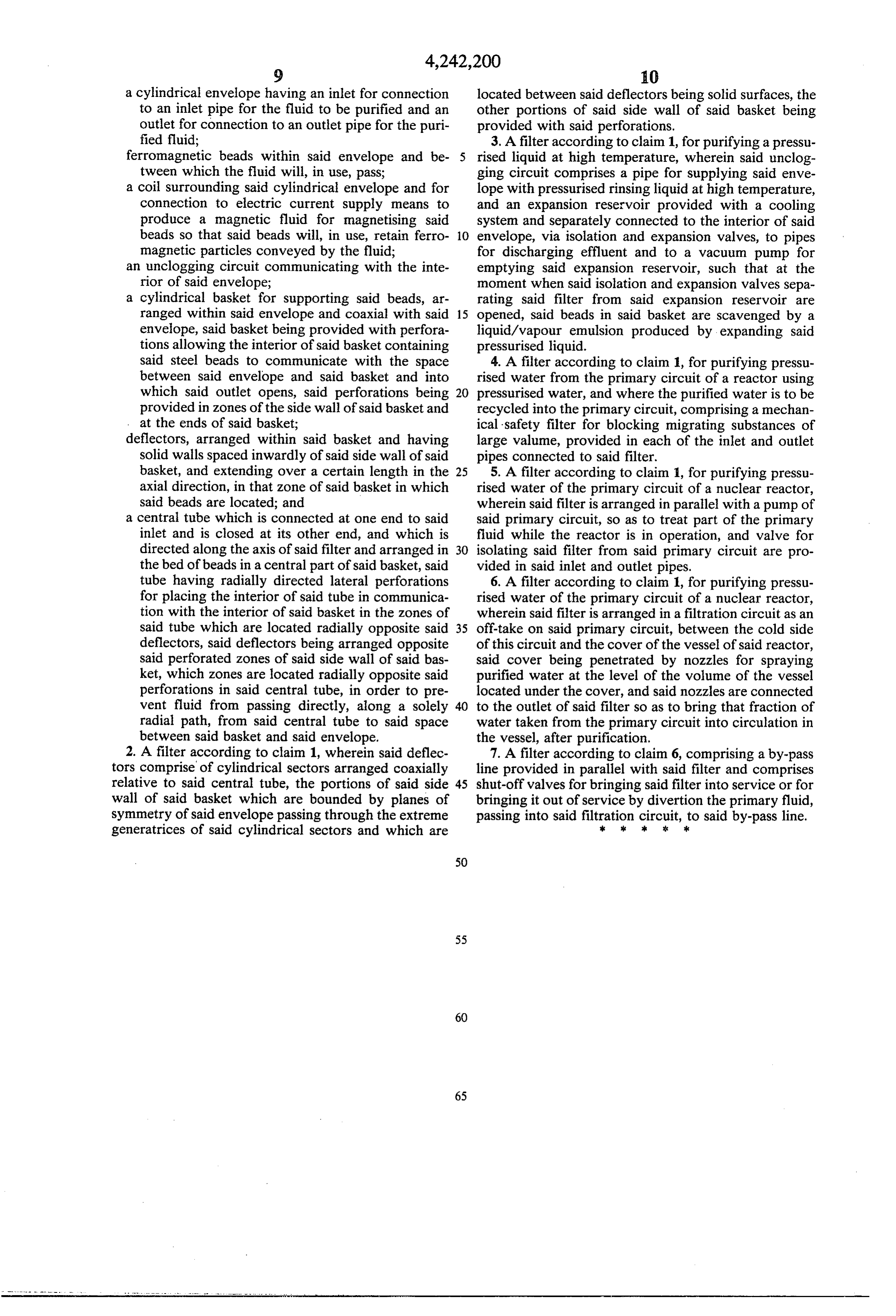
Page 10
UNITED STATES PATENT AND TRADEMARK OFFICE
CERTIFICATE OF CORRECTION
NVENTOR(S) : MICHEL DUBOURG
it is certified that error appears in the above-identified patent and that said Letters Patent are hereby corrected as shown below:
In the. Heading insert:
30l Foreign Application Priority Data
October 5, 1978 FRANCE Applin. No. : 78-28525 signed and sealed this
Nineteenth Day of May 1981
SEAL
RENE D. TEGTMEYER
Attesting Officer Acting Corrissioneer of Petees said Tradesarks
Page 11
UNITED STATES PATENT AND TRADEMARK OFFICE
CERTIFICATE OF CORRECTION
NVENTOR(S) : MICHEL DUBOURG
it is certified that error appears in the above-identified patent and that said Letters Patent are hereby corrected as shown below:
In the. Heading insert:
30l Foreign Application Priority Data
October 5, 1978 FRANCE Applin. No. : 78-28525 signed and sealed this
Nineteenth Day of May 1981
SEAL
RENE D. TEGTMEYER
Attesting Officer Acting Corrissioneer of Petees said Tradesarks
Page 12
UNITED STATES PATENT AND TRADEMARK OFFICE
CERTIFICATE OF CORRECTION
INVENTOR(S) : MICHEL DUBOURG
It is certified that error appears in the above-identified patent and that said Letters Patent are hereby corrected as shown below:
In the. Heading insert:
30l Foreign Application Priority Data
October 5, 1978 FRANCE Applin. No. : 78-28525 signed and sealed this
SEAL
Nineteenth Day of May 1981
Attest:
RENE D. TEGTMEYER
Mittesting Officer Acting Commissioner of Patents and Trademarks
Provenance
- Collection
- Cited prior art
- Original PDF
- patentimages.storage.googleapis.com →
- Filed
- 1979-10-02
- Pages
- 12
- Method
- pdftotext (the PDF's own text layer) + pdftoppm 300dpi page scans
- Source
- Google Patents bibliographic record
- Granted
- 1980-12-30
- Inventors
- Michel Dubourg; Framatome SA
- Transcribed from
- patentimages.storage.googleapis.com →