patent · US4234782
Space heating using off-peak electric heat storage
18 November 1980
Page 1 — bibliographic record
United States Patent (19) (11) 4,234,782 Barabas et al. 45) Nov. 18, 1980 54 SPACE HEATING USING OFF-PEAK 1205755 9/1970 United Kingdom..........w 219/365 ELECTRC HEAT STORAGE Primary Examiner-A. Bartis (75) Inventors: Miklos F. Barabas; William B. Cooke; Attorney, Agent, or Firm-Burns, Doane, Swecker & R. H. Stephen Hardy; Arun Verma, Mathis all of Regina, Canada 57 ABSTRACT (73) Assignee: Saskatchewan Power Corporation, An off-peak, electric, central air heating system for Regina, Canada buildings incorporating a heat storage material that is (21) Appl. No.: 870,711 used to store heat generated electrically during off-peak 22 Filed: Jan. 19, 1978 electrical power periods and to deliver heat on demand. The heat storage material is an alkaline metal or alkaline
Related U.S. Application Data earth metal salt such as Na2SO4, NaCl, CaCl2 and KCl individually or in combination with one another. Gen (63) Continuation of Ser. No. 567,104, Apr. 11, 1975, aban doned.
eration of heat during the off-peak electrical power periods is automatically controlled by an electronic (51) Int. Cl. .......................... HO5B 1/02; F24H 7/04 time clock and time delay circuitry, and by selective 52 U.S. C. .................................... 219/365; 126/400; variable temperature control. The heating unit is con 165/18; 165/103; 165/104 S; 219/364; 219/367; structed with a casing having an inner jacket and an 219/378; 219/491 outer jacket with an air space between the two jackets.
58) Field of Search..................219/341, 378,365, 530, The storage material is surrounded by the inner jacket 540, 325, 326,364, 366, 367, 491-493; 165/104R, and the air space provides insulation as well as an air 104 S, 18; 126/400 passage between the two jackets. The transfer of heat (56) References Cited from the heat storage tank into the building at desired
temperature is achieved by a proportional air flow con trol device and a two speed fan. When air is directed 3,569,669 2/1969 March .................................. 219/378 only through the space between the two jackets, the fan 3,958, 101 5/1976 Barabas. ... 219/378 X runs at low speed. When air is directed through the 3,989,927, 11/1976 ERB ..................................... 29/378 inner jacket containing the heat storage material, the fan FOREIGN PATENT DOCUMENTS runs at high speed. Also disclosed are emergency over 188815 2/1957 Austria ..................................... 219/378 ride as well as other control circuits that operate on 6579973 2/1963 Canada............................ ... 219/365 timed as well as temperature bases to insure proper 2129850 12/1972 Fed. Rep. of Germany ........... 219/378 heating of the space.
1160081 7/1969 United Kingdom ..................... 219/378 11 Claims, 19 Drawing Figures
HIGH TEMPERATUR
ELECTRIC
HEATING
ELEMENTS
- HEAT
ge 18 STQRAGE
BLOCKS
Nrssss SR-rk EE
CERAMIC BRCK TEMPERATURE
NSULATON
Page 2
Drawing sheet — no readable text.
Page 3
Drawing sheet — no readable text.
Page 4
Drawing sheet — no readable text.
Page 5
Drawing sheet — no readable text.
Page 6
Drawing sheet — no readable text.
Page 7
Drawing sheet — no readable text.
Page 8
Drawing sheet — no readable text.
Page 9
Drawing sheet — no readable text.
Page 10
Drawing sheet — no readable text.
Page 11
pour into the blocks. The electrical heating elements
SPACE HEATING USING OFF-PEAKELECTRIC may be coated with a corrosion protective material to HEAT STORAGE prevent corrosion of the heating element by the heat storage material. Such coating can also act as an electri
RELATED APPLICATIONS cal insulating material.
This is a continuation of United States Patent Appli The heating system may be of an open loop type cation Ser. No. 567,104 filed Apr. 11, 1975, now aban wherein the cold air to be heated is separated into two doned. portions, one portion then being heated by the heat This invention consists of an off-peak electrical heat 10 stored in the material before being mixed with the other ing system, and more particularly a heating system unheated portion to provide a blend of warm air. A which utilizes heat that is generated electrically and proportional air flow control can be used to regulate the stored in a heat storage medium during the off-peak relative proportions of cold and heated air thereby pro hours of electricity demand. viding control over the temperature of the blended air This heating system can be used to heat a conven 15 being delivered to the heated space.
tional home in the same manner as a conventional natu The heating system may also be of a closed loop type ral gas or oil furnace, or a central electrical heating wherein cold air to be heated is passed through a heat system. exchanger wherein the cold air is heated by an ex BACKGROUND OF THE INVENTION change of heat with air that has been heated by the heat stored in the heat storage material.
Increased prices of conventional heating fuels and 20 Transmission of electrical power to the heat storage predicted shortages have prompted the adoption of material is controlled by a rechargeable battery fed electric heating in many homes. Since the energy to electronic timer and clock that regulates the period of heat a house exceeds the electrical energy normally time that power is drawn to generate heat for storage in supplied to the home in many areas of North America, total conversion to electric heat would necessitate tre 25 the heat storage material and to heat the building during mendous increases in the electrical generating and heatperiod the of power drawn. The maximum amount of transmission capacity of the utility companies. This controlled by be that can stored in the heat storage material is situation can be alleviated by the use of off-peak elec tively adjusted by the user. control a temperature
A timer that can be selec by-pass control tricity and heat storage for home heating, but units permits a reduced capacity supply of electrical suited to the extreme North American requirements do 30 be drawn for heating when insufficient heat is power stored
not exist. The inventors have invented an efficient off peak, electrical central air heating system for buildings the blocks.
that uses heat that is generated electrically during the The external type heating element is constructed so off-peak power periods and stores the generated heat in that it has a built-in safety feature. It will be appreciated a heat storage material for use during the peak power 35 that if the timer control becomes defective, and electri periods. cal power continues to be delivered to the heating ele ment beyond the normal heating cycle, a dangerous
SUMMARY OF THE INVENTION situation could develop because high temperatures The basic principles of the off-peak electrical heating would be reached, the heat storage material would melt, system is the storage during off-peak electrical power and damage to the furnace could result. Accordingly, periods of heat in a suitable heat storage material. The the heating coil is designed so that it will self-destruct stored heat is withdrawn from the storage material on a itself at a temperaure of 1500'.
"heat-on-demand' basis, thus relieving the electrical The heat tank consists of a unique double jacket de power system of heavy heating loads during peak hours. sign. The heat storage material and the heating elements Operation in this manner leads to more effective utiliza 45 are enclosed in an inner heat tank casing which is insu tion of the generation, transmission and distribution lated with high temperature insulation. The inner heat facilities of the electrical power system. tank casing and high temperature insulation are en Suitable materials for heat storage are inexpensive closed in a second exterior furnace casing that is insu alkaline metal or alkaline earth metal salts such as so lated with low temperature insulation. An air passage dium sulphate (Na2SO4), sodium chloride (NaCl), po 50 exists between the heat tank casing and high tempera tassium chloride (KCl), and calcium chloride (CaCl2), ture insulation and the exterior furnace casing and low individually or in combination with one another. These temperature insulation. Low speed air is constantly salts, or salt mixtures, can be cast or molded into blocks. circulated through the air passage to pick up any casual Binding agents such as silicates, silica, Kaolin, clay or heat that is radiated through the inner heat tank casing fly ash can be used to stabilize the heat storage material 55 and the high temperature insulation. In this way, virtu and grain size can be controlled by temperature control ally all the heat stored in the heat storage material is and additives. utilized to heat the building. Electrical heating elements, which are used in gener When additional heat for the building is required, a ating and transmitting heat to the heat storage material control gate, which controls the proportion of the air are embedded in the material while the material is being 60 that is circulated through the air space between the heat cast or molded, or are wrapped around the circumfer tank and the furnace casing and the air that is circulated ence of the material, or are stacked with the material. through the interior of the tank casing to pick up heat The heating system is designed to operate over heat from the heat storage material, opens a required amount storage material temperatures ranging from about room to permit more air to be circulated to the interior of the temperature to about 1200' F. 65 heat tank casing so as to pick up more heat. The blend The surfaces of the blocks may be sealed with a suit of these two separate circulated air systems is propor able sealing medium to prevent the transmission of ob tionally controlled so that the desired temperature of noxious odors into and out of the blocks, or water va heated air is delivered to the building.
Page 12
The temperature that is to be maintained in the build Among the materials which meet these requirements, ing is controlled by a thermostat that can be selectively but which, as far as is known, have not been applied to set by the user. The thermostat regulates the operation a system that can heat an entire house in the extreme of the furnace fan motor and the control gate motor. cold climate regions of the northern hemisphere, are a When the thermostat demands heat, the furnace fan variety of salts, and mixtures of these salts, heated to motor switches to high speed and the control gate is high temperatures in the region of 1200F. The density operative. Otherwise the fan operates at low speed and and thermal heat storage capacity of these salts in their the control gate is closed to airflow through the heat natural form is low, but the heat storage capacity is tank. considerably improved if the salts are in the form of 10 solid blocks.
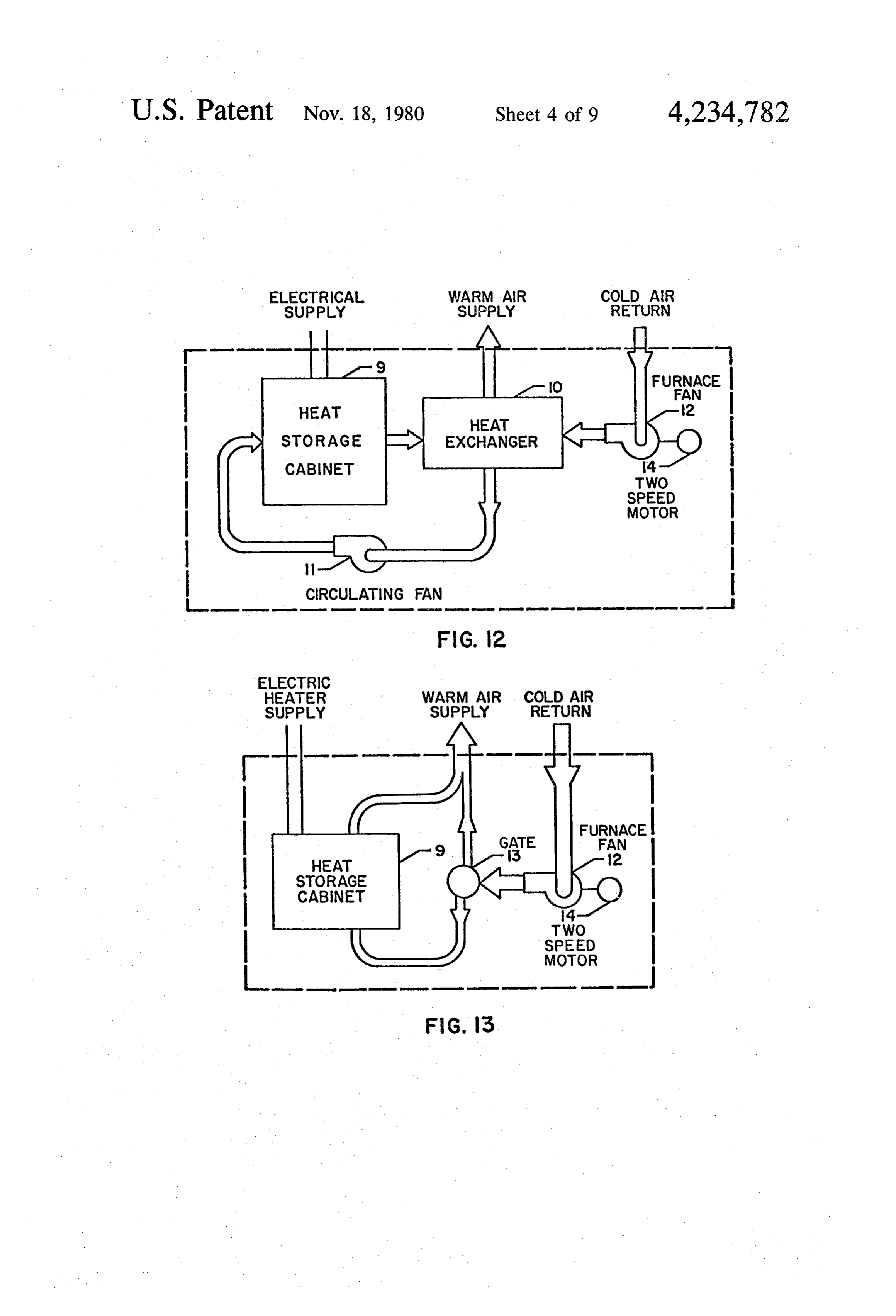
IN THE DRAWINGS
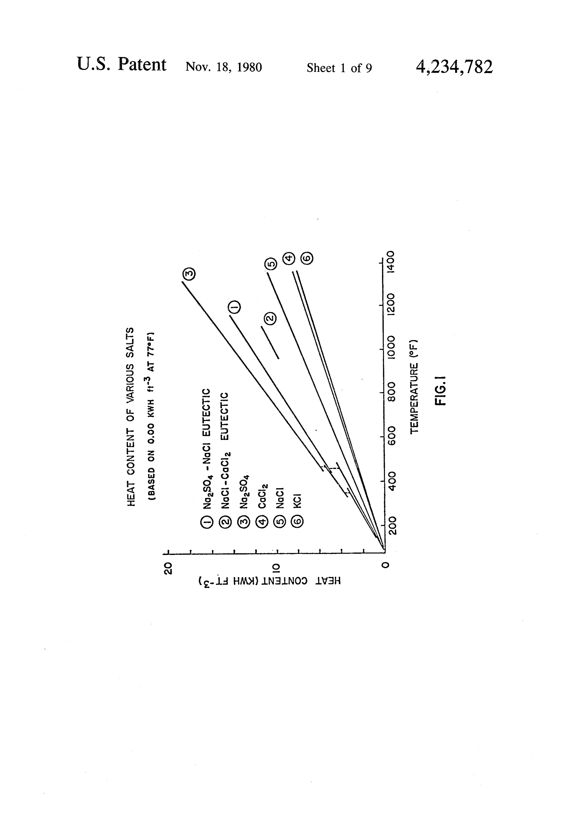
A graphic plotting of heat content per unit volume as
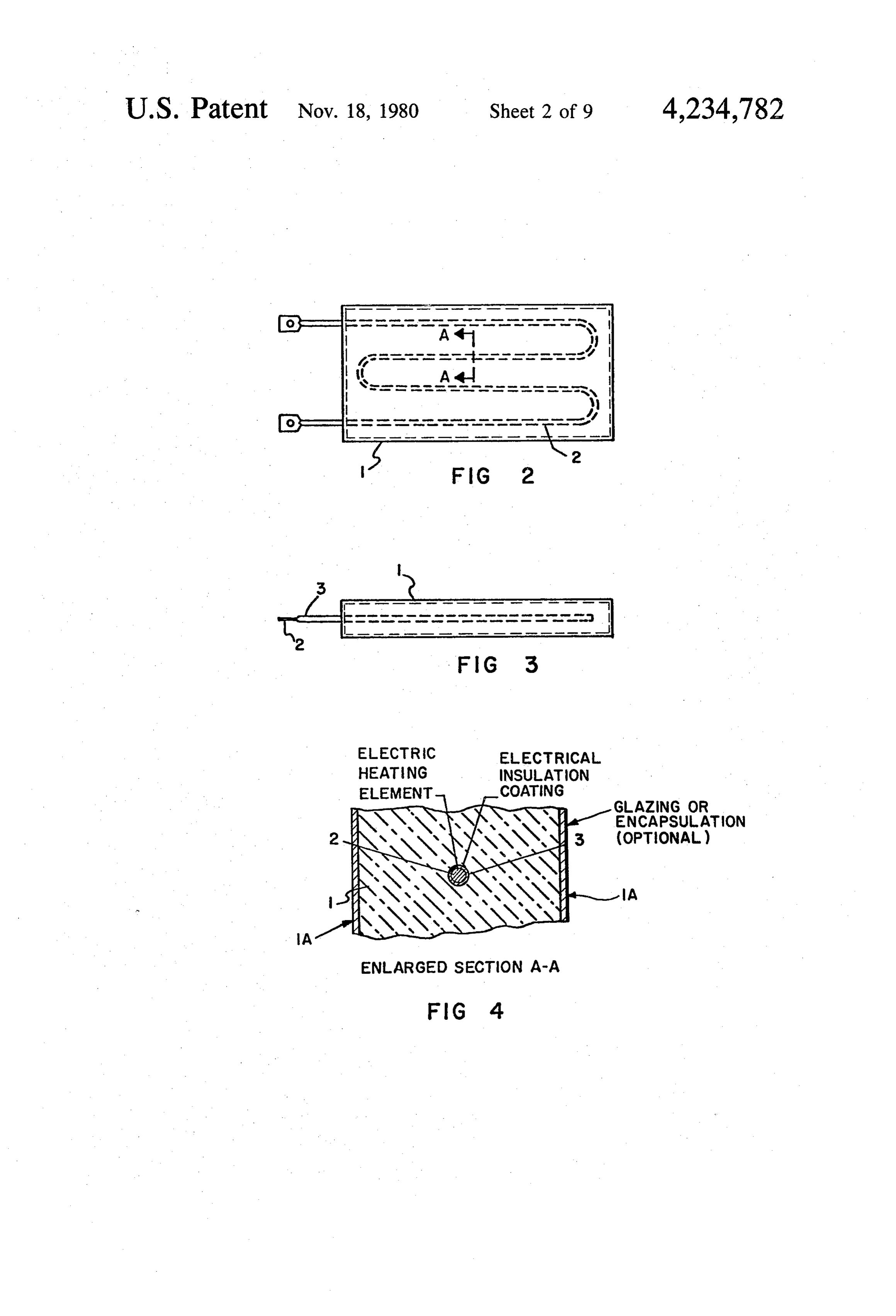
FIG. 1 is a graph showing heat content per unit vol a function of temperature for various salts, and salt ume as a function of temperature for various heat stor mixtures, provides a useful means of evaluating poten age materials; tial heat storage materials (see FIG. 1). The slope of the FIG. 2 is an elevational view of an internal type heat 15 line indicates heat content per unit volume per degree of ing element embedded in heat storage material; temperature. Generally, the steeper the line, the more FIG. 3 is a side view of the heat storage element and satisfactory the material. Materials having maximum heat storage material shown in FIG. 2; heat capacity per unit of volume per unit of temperature FIG. 4 is an enlarged sectional view taken along 20 can therefore be readily identified.
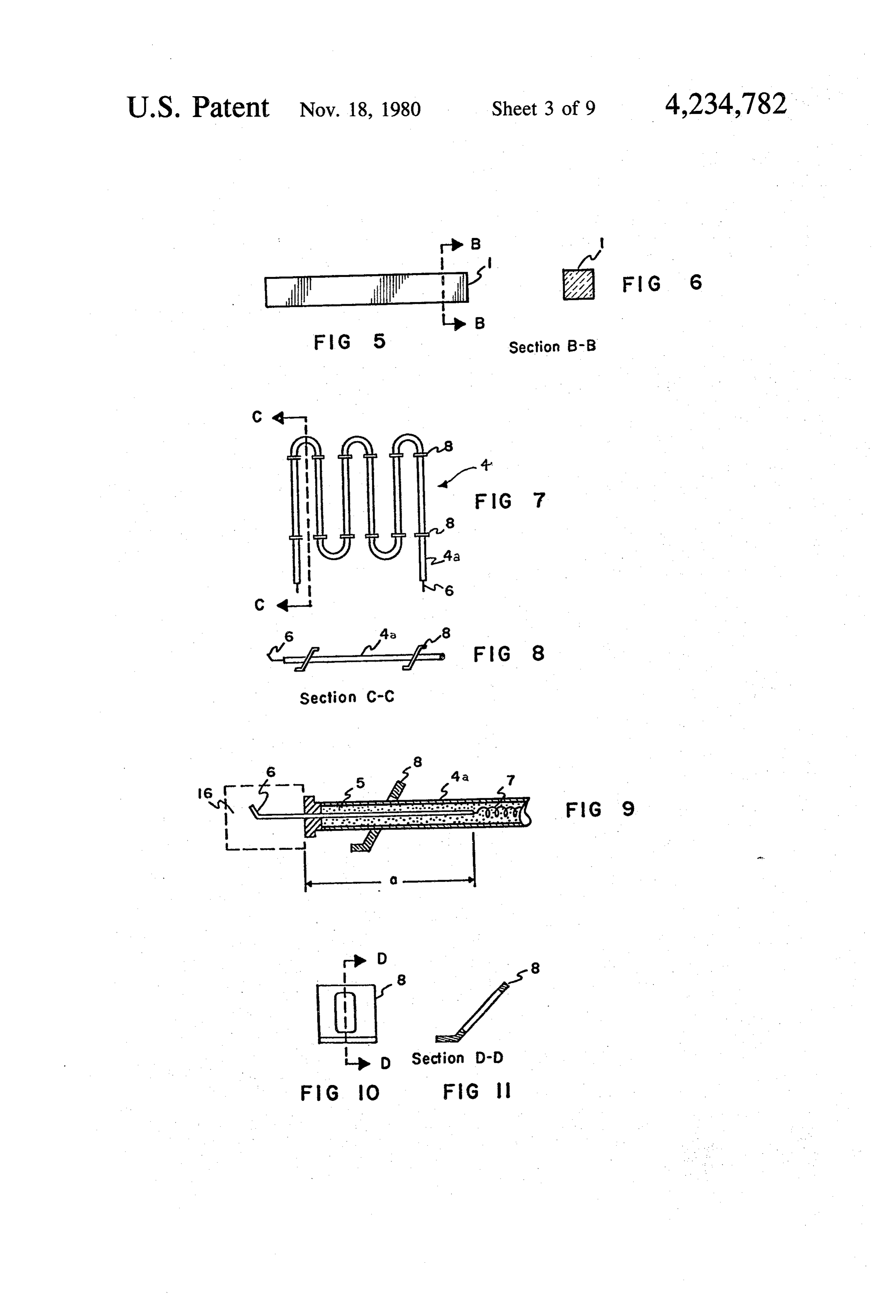
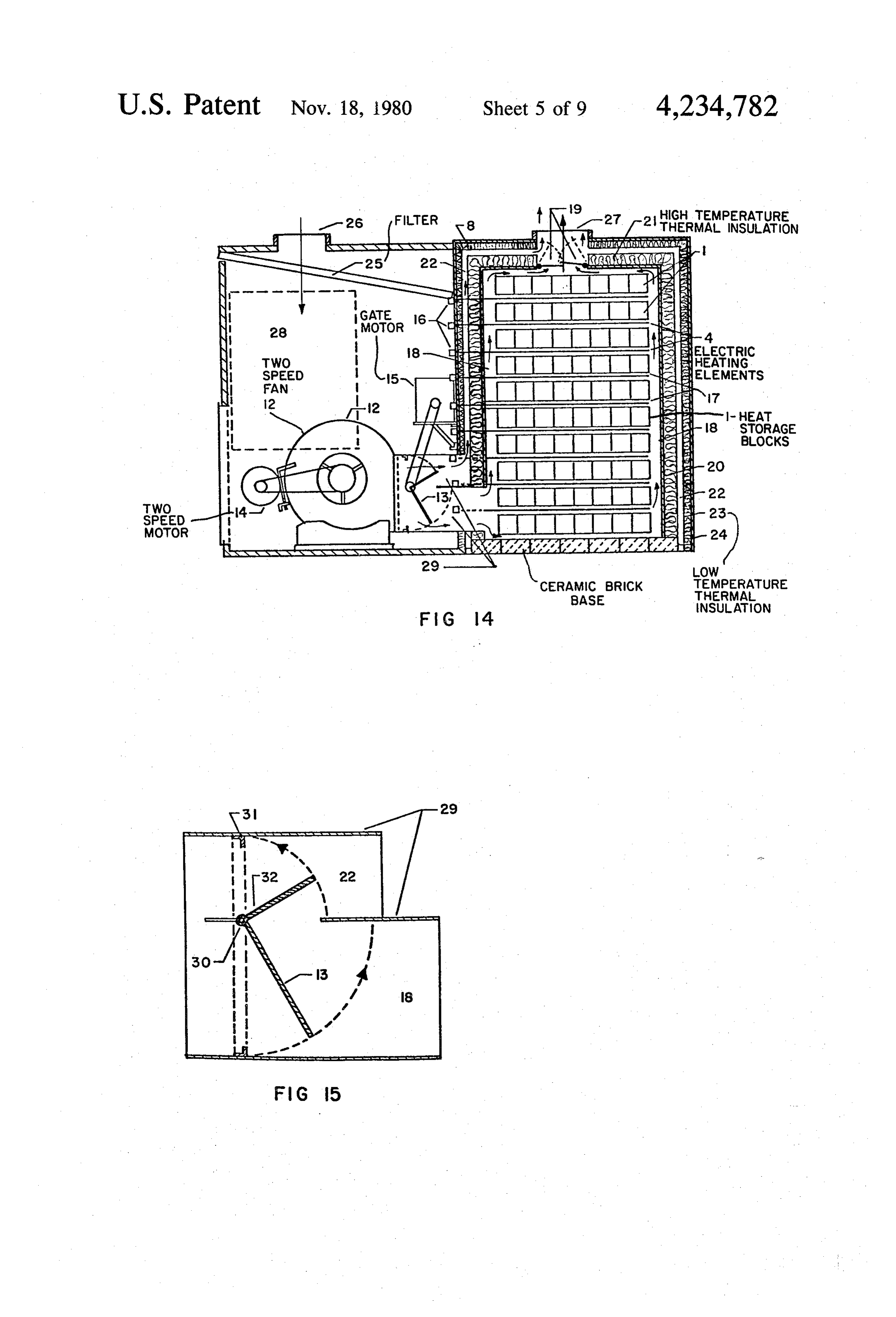
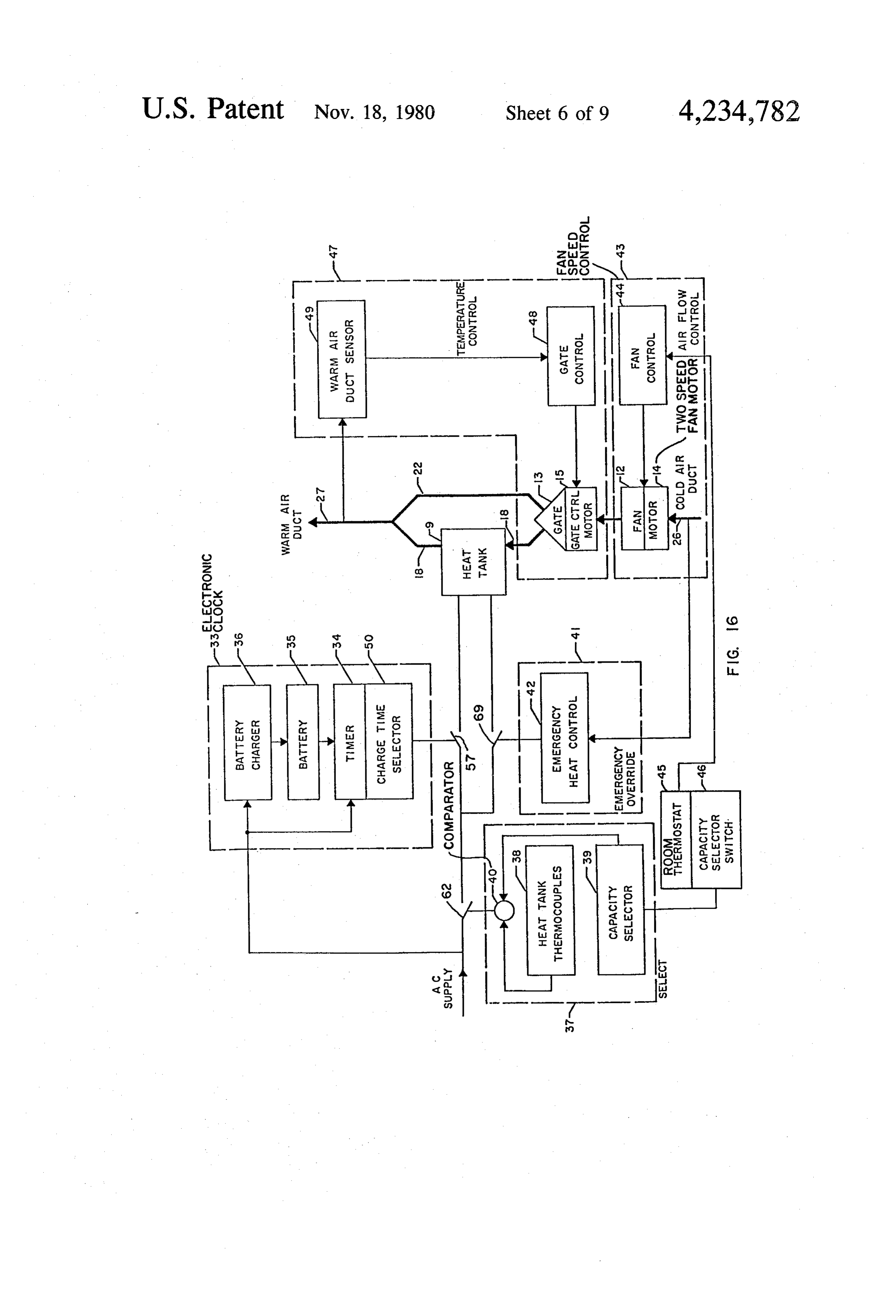
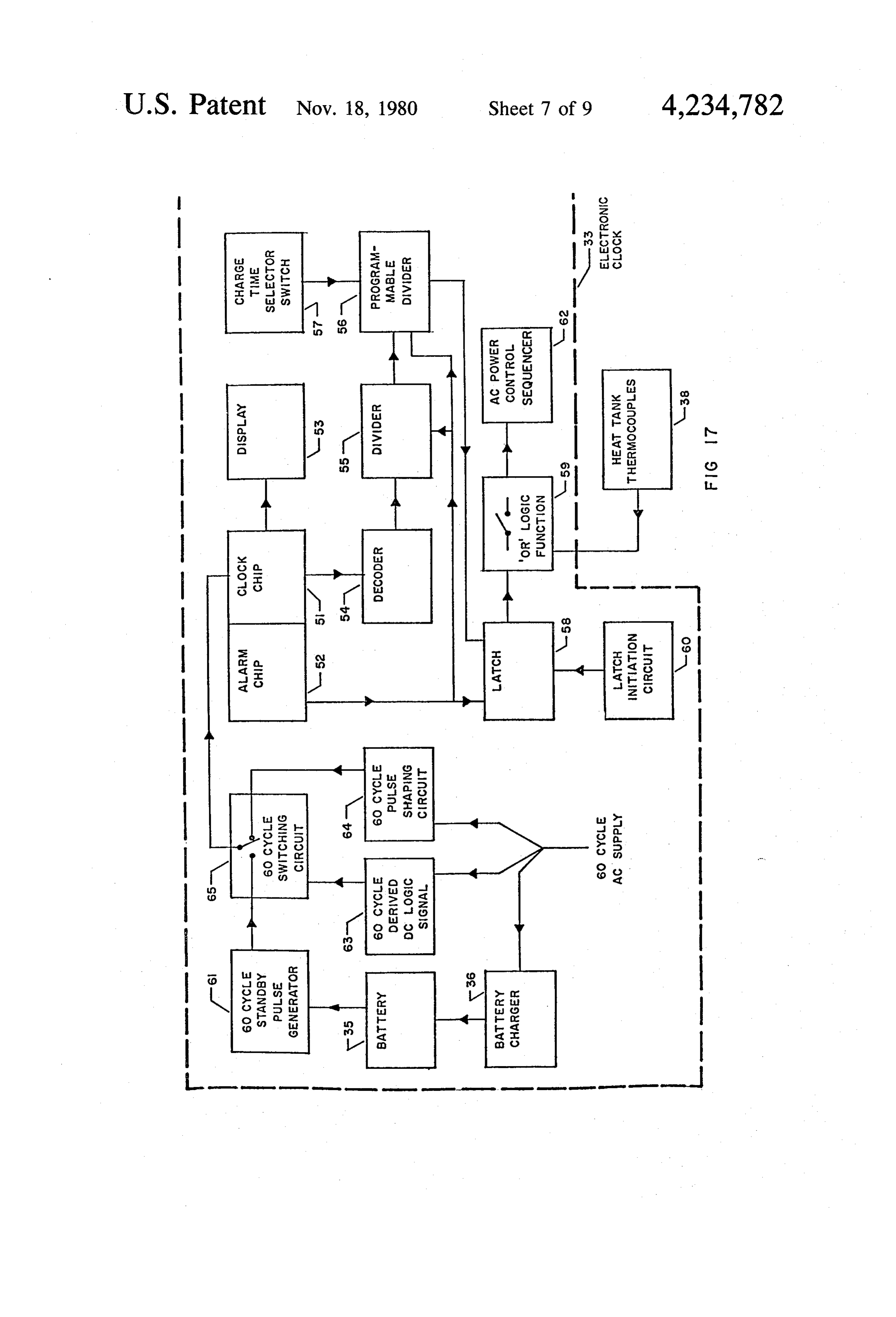
Section A-A of FIG. 2; The applicant's heat storage system is intended to FIG. 5 is an elevational view of the heat storage operate with heat storage material temperatures ranging material used in association with an external type heat from about room temperature to about 1200' F. It has ing element; been found that over this wide range of temperatures, FIG. 6 is a sectional view taken along Section B-B 25 the blocks tend to disintegrate and crumble with time. of FIG. 5; This is undesirable because the blocks lose much of their FIG. 7 is an elevational view of an external type heat storing ability. It has been found that the stresses in electrical heating element; the block can be reduced by addition of other salts. It FIG. 8 is a sectional view taken along Section C-C has also been found that artificial binding agents can be of FIG. 7; used to strengthen the block structure. Silicates, silica, FIG. 9 is an enlarged partially cut away view of FIG. 30 Kaolin, clay, fly ash, and similar materials, have been 8 showing details of construction of the external type found to be useful as binding agents. The binding agent heating element; is believed to matricize the salt and thus the salt block FIG. 10 is an elevational view of an external type resists thermal cracking due to expansion and contrac heating element stand; 35 tion in the operating temperature range of about room FIG. 11 is a sectional view taken along Section D-D temperature to about 1200' F. Grain size control of FIG. 10; through process temperature control and grain refine FIG. 12 is a diagrammatic representation of a closed ment additives are also important.
loop heating system; Suitability of the heat storage material must also be FIG. 13 is a diagrammatic representation of an open considered from the standpoint of casting temperatures loop heating system; and maximum system design temperature. Each salt has FIG. 14 is a partially cut away side view of a heating a certain melting point, and mixtures of salts have differ system using external type heating elements; ent melting points than the pure salts. FIG. 15 is an enlarged view of a split cold air duct Salts, and mixtures of salts, which have very high with the control gate in half-open position; 45 melting points are not generally satisfactory because of FIG. 16 is a diagrammatic representation of an open the difficulty in casting blocks from such salts and salt loop heating system including controls; mixtures. On the other hand, salts, and mixtures of salts, FIG. 17 is a block diagram of the electronic clock which have low melting points are not generally satis control circuit; factory because they might melt during peak block FIG. 18 is a block diagram of the capacity control 50 operating temperatures of the heating system. circuit; A block of heat storage material can be constructed FIG. 19 is a block diagram of the emergency override by casting or molding. Casting is done by melting the circuit. salt or salt mixture and then solidifying the salt or salt DESCRIPTION OF THE INVENTION mixture into blocks. However, casting is not recom 55 mended for blocks that are intended to be operated
Selection of a suitable heat storage material is an frequently attemperatures of 1200' F. It has been found important feature of this invention. Suitable heat stor that a cast block is somewhat brittle and will tend to age materials will have the ability to store (1) a maxi crack. On the other hand, casting is advantageous be mum amount of heat within (2) a minimum volume over cause it provides an easy method of embedding the (3) a minimum temperature rise, with (4) the material 60 element in the salt.
being always in solid phase. Because salts are electrically low conductive materi Countries like Canada, which experience very low als in the solid state, casting is recommended for low climatic temperatures in the winter, for efficiency rea voltage type heating elements (20 to 25 volts) since sons, cannot rely on large volume heat storage materials better adhesion and thus heat transmission are obtained. because in order to provide sufficient capacity large and 65 A spray on or dip coating of electrical insulating mate bulky storage units are required. Furthermore, the heat rial such as MgO or the like is recommended to increase storage material must meet such practical requirements heat transmission between the salt and the element, as low cost, ready availability and ease of handling. MgO is also advantageous because it acts as a corrosion
Page 13
protection material. Other suitable coating materials FIG. 10 shows in detail the construction of the slip on can also be used. stand 8 in elevation while FIG. 11 the cross section FIGS. 2 and 3 show a typical cast type heat storage detail.
block comprising heat storage material 1 and internal FIGS. 12 and 13 show diagrammatic concept of the heating element 2. FIG. 4 shows in sectional manner the overall heat storage system. The heat storage materials heat storage material casted on the internal heating 1 and heating elements are grouped together and insu element 2 which is coated by insulating material 3. lated to provide a heat storage cabinet (heat tank) 9. In order to construct a heat storage block by mold The amount and number of heat storage materials and ing, the selected salt, or salt mixture, along with an 10 heating elements are variable depending on the heat inorganic binding agent such as silicate, Kaolin, clay, fly storage capacity that is required. ash or similar material, is wetted by 5 to 10 percent of an FIG. 12 shows a closed loop system, in which heated organic liquid binder, such as latex, and is compressed air is circulated from a heat storage cabinet 9 to a heat at pressures of 10,000 psi or more into the desired block exchanger 10 by means of a circulating fan 1. The heat form. The block is then dried and prebaked at about 15 exchanger 10 transfers some of the heat from the heated 500 F. temperature. Once the block has cooled down air from the heat storage cabinet 9 to the cold air that is to about room temperature, it is baked again at 1200' F. drawn from the space to be heated through the cold air temperature. These temperatures represent the limits of return by means of the furnace fan 12. The warmed air the temperature cycle over which the block will be istional circulated back to the heated spaced as in a conven forced air central heating system through the operated during the heat storage process.
A third method of forming the salt blocks is by sinter 20 warm air supply.
FIG. 13 shows an open loop system where a con ing the salt or mixtures of the salt attemperatures below trolled portion of the cold return air from the space 1200' F. The shape of the block chosen depends usually being heated on the particular construction of the overall heating and picks up passes through the heat storage cabinet 9 system. However, as a general rule, a slab shape rather 25 portion of theheat. It is then mixed with the remaining unheated air to provide warm air to the than a plate shape is preferred in order to equalize the space being heated at the required temperture. The ratio heat stresses which occur in the block at the high oper of warmed air to cold air to provide air of the required ating temperatures. temperature is controlled by control gate 13. The blocks can also be formed with interlocking One factor for making a choice between the open endentments to provide air space and heater space when 30 loop and closed loop systems stacked, though the same purpose can be achieved using heat storage material tends todepends trap on whether the and subsequently spacers made of metal or some other suitable material. release odors. Certain materials will trap odors as they A typical slab for use in association with an external cool and then release them during a warmup period. type heating element is shown in FIGS. 5 and 6. A row Such materials would normally require the closed loop of slabs is used to create a heat storage block. A vertical 35 design to avoid odors being circulated throughout the column of heat storage blocks is used to create the total space being heated, such as a house. desired heat storage mass. Alternatively, the surface of the heat storage material FIGS. 7 to 1 inclusive illustrate the construction of a can be sealed by encapsulation, or by glazing 1A to the external type heating element. 4. Essentially it is a prevent the transmission of odors into and out of the radiant type tube heater which has a high temperature 40 heat storage material 1, if this provides a cheaper system sheathing 4a, such as a nickel alloy. A special feature of with equally satisfactory operation. the heater 4 is the long electrical lead 6 which is con FIGS. 14 and 15 show partially cut away side views structed of a high electro-conductive material. Very of the heat storage system and the air flow control gate little hea is generated over this distance thereby creat as used in an open loop system with external type heat ing a coid lead out of the heat tank 9 through insulation 45 ing elements 4.
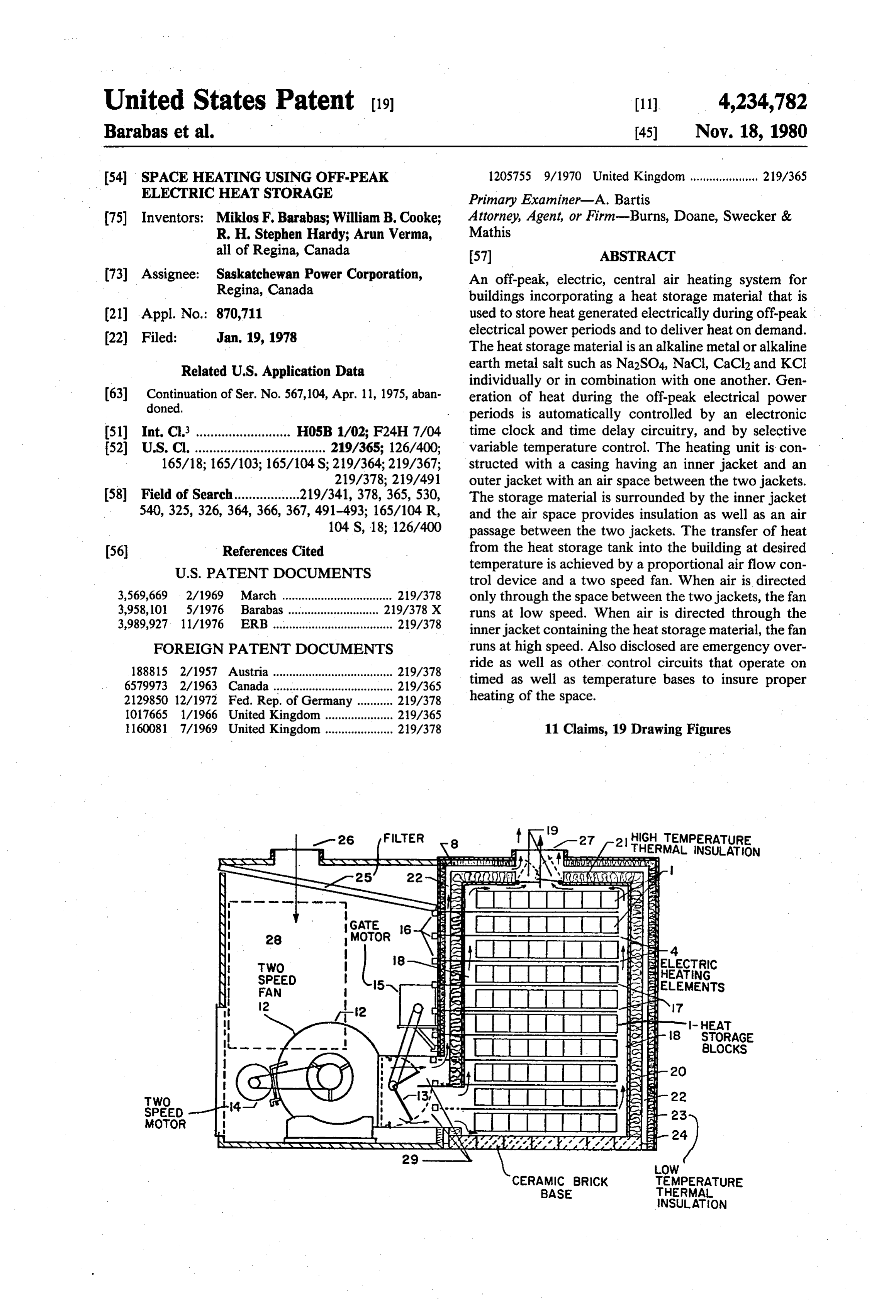
2. The heat generating and heat storage part of the The heating element is so designed that if something heating system is constructed of heating elements and goes wrong and power continues to be fed to the heat basic blocks or modules shown in FIG. 14 as a verti ing element, the heating element will burn out once a cally disposed series of heat storage slabs arranged hori sheath material 4 temperature of 1500 F. is reached. SO Zontally to form blocks. FIG. 14 shows eight slabs in This self destructing safety feature protects the heat each block. These blocks 1 are disposed vertically one tank 9 because the element burns out before the melting above the other in spaced relation and including exter point of the heat storage material is reached. nal type heating elements between each of the blocks. As may be seen in FIG. 7, the heating element 4 is FIG. 14 shows ten blocks vertically disposed one above constructed to traverse back and forth several times to 55 the other and nine external type heating elements 4 increase its heat generating ability over a given area. inserted in the nine air spaces that exist between the FIG. 9 shows the constructional details of the heating stack of ten blocks.
element 4. The electrical lead 6 and the heating coil 7 The heat storage blocks 1 and accompanying external are encased in a compressed and vitrified ceramic insu type heating elements 4 are enclosed in an insulated heat lating material 5. The distance "a' of the “cold’ electri 60 tank casing 20. The exterior surface of the heat tank cal lead 6 corresponds to the thickness of insulation 21, casing 20 is insulated with high temperature ceramic air passage 22 and insulation 23 in FIG. 14. wool insulation 21 that is sprayed on the exterior sur The heating element 4 is maintained in spaced rela face of the heat tank casing 20. Heat tank casing 20 is of tion with the heat storage material 1 when in stacked sufficient dimensions to provide an air space 18 about relationship with one another by means of stands 8 65 the exterior of the heat storage blocks 1 and external located at various positions on the overall heating ele type heating elements 4.
ment 4 (See FIG. 7). These stands are constructed of a Enclosing the insulated heat tank casing 20 is an exte suitable metal and slide onto the heating element 4. rior furnace casing 24. The interior of the furnace casing
Page 14
24 is insulated with low temperature insultion 23, The the interior of the heat tank enclosed by heat tank casing dimensions of the furnace casing 24 and the insulation 20. The air flows past and circulates about the hot heat 23 are sufficient to allow for an air space 22 to surround storage blocks 1 and picks up heat from these heat stor the heat tank casing 20 and high temperature insulation age blocks 1. The heated air then exhausts through hot 21 on all four sides and the top of the heat tank casing air pressure gates 19 for delivery through warm air duct 20. Air space 22 permits low speed cool air to be circu 27 to the building being heated. It will be seen that lated
between the heat tank casing 20 and furnace cas when air flow control gate 13 is not in a fully open or closed position, the air that is circulated through low external type heating elements 4 penetrate speed air passage 22 and the air that is circulated past through one wall of the heat tank casing 20, the high 10 heat storage blocks 1 are allowed to mingle with one temperature insulation 21, low speed air passage 22, low another as they reach warm air duct 27. By varying the temperature insulation 23 and furnace casing 24 and ratio of these two volumes of air, warm air of a specified each heating element 4 is connected to a separate elec temperature can be obtained. The ratio of the two vol trical connector 16. Electrical power to be used in heat umes of air is controlled by the position of air flow ing each of the elements 4 is delivered through each of 15 control gate 13. The temperature of the air being deliv the connectors 16.
The heat storage block 1, external type heating ele air flow control gate 13 are sensed the ered through warm air duct 27 and position of the ment 4, and heat tank casing 20 combination rest on a controls which will be discussed later incontrolled and this
descrip suitable high temperature surface such as ceramic brick. tion.
An extension of the outer furnace casing 24 provides an enclosure in which fan 12, dual-speed fan motor 14, is, When control gate 13 is in a fully raised position, that gate control motor 15, cold air filter 25, and split air flowrotated completely counter-clockwise so that the of air to the low speed air passage 22 is completely duct 29 are housed. Cold air filter 25 removes dust and other unwanted particles from the col air being re shut off, all the air pumped by furnace fan 12 passes turned to the furnace through cold air duct 26. 25 through header air passage 18 to the interior of the heat A furnace control box 28 is located on the outside of tank 9.
the outer furnace casing 24. This control box 28 en The two-speed motor 14 runs at low speed when closes all of the electronic controls used in operating the control gate 13 is in a closed position, that is, rotated as furnace except for capacity selector switch 46 and ther far as possible in a clockwise direction. However, when mostat 45. These latter controls are located in the build 30 control gate 13 is adjusted to any other position by gate ing being heated. control motor 15, the two-speed motor 14 runs at high Heated air from the furnace is delivered to the build speed. The motor 14 running at high speed drives fur ing being heated through warm air duct 27. A pair of nace fan 12 at a high speed thereby maintaining high hot air pressure gates 19 are located in the warm air speed air flow through the heat tank enclosed by heat duct 27. These hot air pressure gates 19 are in a raised 35 tank casing 20. A blend of air, one volume of which position when warm air is being pumped from the fur passes through low speed air passage 22, and the other nace through warm air duct 27. However, when warm volume of which passes through header air passages 18, air is not being pumped through warm air duct 27, these and air passages 17, is used to maintain the exit tempera hot air pressure gates drop to a closed position thereby ture of the warm air being delivered through warm air closing the warm air duct 27. These hot air pressure 40 duct 27 at about 250 F. The relative proportions of air gates 19 help prevent undesired objects being dropped are controlled by warm air duct sensor 49 acting in into the interior of the heat tank casing 20. co-operation with gate control 48. Gate control 48 op FIG. 15 shows the split duct 29 and air flow control erates gate control motor 15 which adjusts control gate gate 13 in detail. The control gate 13 is constructed of 13 to the proper position to obtain a bledn of air of the asbestos, or similar hard surface insulating material, and 45 required temperature. A discussion of these respective attached to control gate fitting 32. Control gate 13 and controls is presented in more detail later in this descrip fitting 32 pivot through about 90 degrees about gate tion.
pivot 30. The position of control gate 13 is controlled by Most of the components can be constructed of mild gate control motor 15. Control gate seal 31 limits the steel. The heat tank casing 20 can be constructed of rotation of gate 13 to about 90 and provides an air seal 50 light weight mild sheet steel and riveted, welded or with one edge of gate 13 whenever the gate 13 is in a bolted and insulated with high temperature insulation completely open or closed position. 21 as a separate prefabricated unit. The outer casing 24 The constructional material selected for control gate can also be constructed of light weight mild sheet steel 13 must resist the heat radiated by the heat storage covered with the low temperature insulation 23. The material 1 and heating elements 4. Control gate 13 is 55 slabs and blocks comprising the heat storage material 1 shown in FIGS. 14 and 15 in an intermediate position. can be packaged and shipped separately to ease han As can be seen, when the gate 13 is rotated clockwise, dling. The furnace fan 12, control gate 13, two-speed the gate 13 shuts down the main air flow passing fan motor 14, gate control motor 15 and the compact through header air passage 18 and permits air to pass electronic control box 28 can also be packaged and through low speed air passage 22. When gate 13 is in 60 shipped separately.
this position, the fan motor 14 runs at low speed and The modular design for the respective components of drives air at low speed through low speed air passage 22 the furnace has been developed so that all sizes and which completely surrounds the heat storage area on al weights will meet shipping regulations, and the largest sides except the bottom. This system ensures that most item will fit through entrance doors the widths of which of the heat that is lost through high temperature insula 65 are specified by local and national building code(s). The tion 21 is not wasted. heaviest component weight is designed to be less than When control gate 13 is rotated counter-clockwise, the weight that two men can lift as specified by local air is permitted to flow through header air passage 18 to and national labour code(s).
Page 15
The electrical heating elements in or between the means of a capacity selector switch 46 connected to a heat storage material 1 of the heat storage cabinet 9 resistive voltage divider. This scheme has the advantage should have sufficient capacity to provide for both of high accuracy, the accuracy being limited only by heating the building and storing heat during the off the accuracy of the thermocouple, and of the reference peak hours of electric power supply, the stored heat voltage.
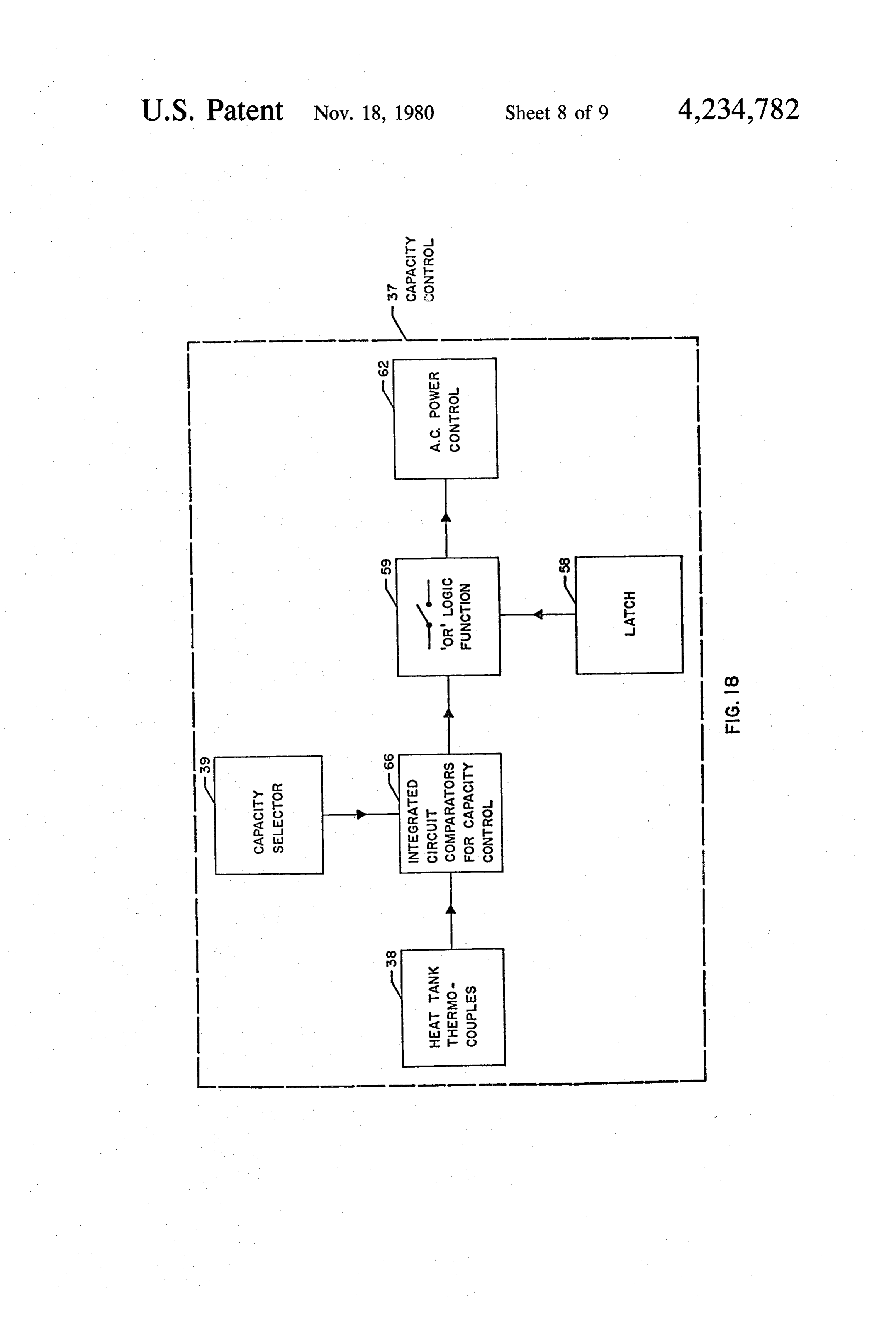
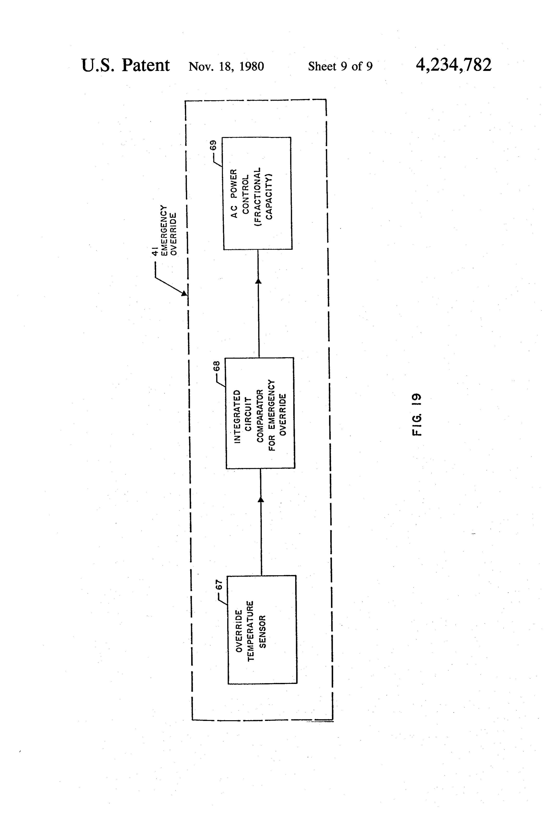
capacity being determined by cycle of operation. For THE EMERGENCY OVERRIDE unit is an emer. example, if 180 KWhr is the estimated maximum heat gency timer by-pass control identified as 41. The emer requirement for a 24 hour period and electricity is to be gency heat control 42 serves to limit the minimum tem drawn for only 8 hours during the night, the heating perature to which the temperature of the heated space elements musth have 180/8=22 KW capacity. 7 kW 10 may drop to as a result of power failure during the are required during the 8 hour period for home heating, charging cyele, or other cause of insufficient heat. The representing 60 KWhr, the remaining 15 kW are re emergency override operates at a preset temperature, quired for heating the blocks to store 120kWhr of heat determined by the fixed component values used in the for the 16 hour period when electricity is not being design. At the present temperature, a fraction of the drawn. 15 heating system capacity will be energized indepen It can be seen that the heating system will draw large dently of the setting of the clock 33 and timer 34. amounts of power during the night for both direct air The emergency heat supply may be activated by heating as required and heat storage block heating, and either a thermal switch or a thermocouple output com will deliver the stored heat during the day according to pared to a preset voltage. By either of these means, a the rate that heat is lost from the house. 20 limited amount of electric heat is supplied to the heated FIG. 16 shows a diagrammetric concept of the open space by-passing the clock 33 and timer 34. This emer loop heating system and the associated control modules gency override feature is set to function only when the described as units, namely, CLOCK, SELECT, capacity selector switch 46 is in a heating position (as EMERGENCY OVERRIDE, AIR FLOW CON opposed to “off” or "fan'). This heat supply is limited
TROL, and TEMPERATURE CONTROL. 25 since a power failure might affect a sizable region and The CLOCK unit is an AC or DC supplied electronic the electrical distribution system would not cope with clock 33 and electronic timer 34. The clock 33 and the full electric heating plus peak daytime loads. The elec timer 34 serve the function of providing a control signal trical power supply by emergency override is sufficient to supply power to the heat storage material for a prede only to insure that freezing temperatures will not occur termined interval every 24 hours. In order to provide 30 in the heated spaced under such conditions. continuous operation, even in case of power failure, the The AIR FLOW CONTROL unit is identified as 43. clock 33 is powered by a battery 35. The battery is It consists of a fan control 44 which is actuated by a continuously trickle-charged by the battery charger 36 thermostat 45. The two speed fan motor 14 runs at when power is available. The clock 33 and timer 34 either low speed or high speed depending upon the circuitry employ integrated circuits to reduce power 35 signal received from the thermostat 45. drain to the point where small, inexpensive, recharge The TEMPERATURE CONTROL unit identified able batteries can be used. as 47 serves to ensure that the warm air entering the Digital logic switching is employed to automatically heated spaced through warm air duct 27 is maintained switch from the usual sixty cps power frequency to an at an acceptable temperature level. The airflow control onboard cps oscillator/frequency divider. This feature gate 13 is driven by gate control motor 15 which is eliminates the need for an electromechanical relay. energized by the high speed terminal of the two-speed The implementation of a variable charge timer (eight, fan motor 14, via gate control 48. Upon energization, nine or ten hours) by the charge time selector 50 is the gate 13 starts to open until the temperature of the air accomplished by decoding the seven-segment output emitted from warm air duct 27 is at the desired. level. pulses from the "minutes' digit on a digital alarm clock 45 The gate control motor 15 is shut down by gate control integrated circuit. One pulse every ten minutes is ob 48. If the air temperature sensed by warm air duct sen tained and is then divided and counted to obtain the sor 49 is higher than desired, gate control 48 will re correct timer period. verse the rotation of the gate control motor 15 thereby This clock 33 and timer 34 scheme provides higher closing air flow control gate 13 until the outlet thermo accuracy than is possible with a resistor-capacitor dis 50 couple temperature of the air emitted from warm air charge timer and, more importantly for this application, duct 27 is at the desired level. Gate control 48 closes a much lower power drain than is possible with electro gate 13 when fan control 44 switches fan motor 14 from mechanical timers. high speed to low speed. Air then flows only through The SELECT unit is a variable capacity control low speed air passage 22 thereby utilizing any casual identified as 37. This capacity control 37 is adjustable 55 heat that escapes through insulation 21. and serves to set the maximum energy to be stored in Several block diagrams are disclosed illustrating the the heat storage material 1 at the choice of the user. operation of the various control modules in detail. This capacity control 37 functions by specifying the FIG. 17 shows a block diagram for the electronic maximum heat storage material temperature at which clock 33. Clock chip 51 generates electrical signals to power to the heat storage material 1 is switched off. drive display 53. Display 53 consists of seven-segment The temperature of the heat storage material 1 is readouts which give an indication of both the time and sensed by heat tank thermocouples 38. An integrated the alarm time stored in alarm chip 52. In a specific circuit comparator 40 compares the thermocouple out embodiment, clock chip 51 and alarm chip 52 would put voltage to a reference voltage set by the capacity most economically be combined into one integrated selector 39. Once the thermocouple voltage reaches the 65 circuit.
reference voltage, an output signal from the comparator A portion of the seven-segment outputs of clock chip 40 actuates circuitry to switch off the power to the heat 51 are applied to decorder 54 to produce a train of storage material 1. The reference voltage is adjusted by pulses of a known period. This train of pulses is further
Page 16
divided in frequency by divider 55 to produce a train of FIG. 18 shows a block diagram for the capacity con pulses of lower frequency. The output of divider 55 is trol 37. Heat tank thermocouples 38 (located in the heat then applied to programmable divider 56. Programma tank) sense the temperature in the heat tank 9 and pro ble divider 56 provides one output pulse according to a duce an electrical output which varies with the temper time interval selected as the charging time of the heat ature of the heat tank 9. Integrated circuit comparators storage furnace. The charging time can be manually for capacity control 66 compare the electrical output selected by charge time selector switch 57. A typical generated by heat tank thermocouples 38 with the elec embodiment would allow charge times of either 8, 9 or trical output generated by capacity selector 39. Capac 10 hours, allowing the same furnace and control system to be used in dewllings of different sizes and heating 10 ity selector 39 generates a number of discrete values of electrical output, each value corresponding to a certain requirements.
Alarm chip 52 can be programmed to provide an heat tank 9 temperature. These discrete values of elec electrical output at a preset time. This preset time corre trical output are manually selectable by capacity selec sponds to the time at which the charging cycle of the tor the switch 46, which is located in an accessible area of building.
furnace (heat storage tank 9) is to be initiated. The elec 15 trical output of alarm chip 52 is used to set latch 58. The 66 produce ancircuit
Integrated comparators for capacity control output of alarm chip 52 also resets divider 55 and pro output of heat electrical tank output whenever the electrical thermocouples 38 indicates a heat grammable divider 56. Latch 58, upon receiving the electrical output of alarm chip 52, produces an electri tank 9 temperature below the preset value correspond cal output until a reset pulse from programmable di 20 ing to the output of capacity selector 39. If the heat tank vider 56 is received. This reset pulse from programma 9output temperature is above the preset value, no electrical is produced by integrated circuit comparators ble divider 56 then causes the electrical output of latch 58 to be removed after the selected charge time (i.e. 8, for capacity control 66.
9 or 10 hours) has elapsed. Latch 58 produces an electrical output during the Latch initiation circuit 60 resets latch 58 upon initial 25 charge cycle time as controlled by electronic clock 33. application of power to the circuit, thus ensuring that, The outputs of latch 58 and integrated circuit compara initially latch 58 has no electrical output. tors for capacity control 66 are both applied to “OR” The outputs of latch 58 and heat tank thermocouples logic function 59. “OR” logic function 59 provides an 38 are both applied to “OR” logic function 59. “OR” logic electrical output whenever both the latch 58 and inte function 59 provides an electrical output whenever both 30 grated circuit comparators for capacity control 66 indi the latch 58 and heat tank thermocouples 38 indicate cate that the heat tank 9 should be charged. The electri that the heat tank 9 should be charged. Heat tank ther cal output of “OR” logic function 59 is removed when mocouples 38 produced an electrical output whenever ever latch 58 is reset, indicating the end of a charging the temperature in the heat tank 9 drops below a preset cycle, or whenever integrated circuit comparators for value. The electrical output of “OR” logic function 59 is 35 capacity control 66 indicate that the preset heat tank 9 removed whenever latch 58 is reset, indicating the end temperature has been reached.
of a charging cycle, or whenever heat tank thermocou “OR” logic function 59 drives AC power control 62. ples 38 indicate that the preset heat tank 9 temperature AC power control 62 is designed to apply power to the has been reached. heat tank heating elements in sequence so that full load DC power for the circuitry of electronic clock 33 is is not applied to all of the heat tank heating elements at provided by battery charger 36 and battery 35. When sixty cycle AC power is available, battery charger 36. the at same time. AC power control 62 staggers the times which the individual heating elements are switched provides DC power to the circuitry as well as to charg on, thereby ensuring that a large surge is not drawn ing battery 35. When sixty cycle AC power is not avail from the power able (due to power outages), battery charger 36 does 45 FIG. 19 showsline. a block diagram for the emergency not function and battery 35 supplies power to the cir override 41. Override temperature sensor 67 senses the cuitry of electronic clock 33. temperature of the air in the cold air return duct 26 of Timing pulses for clock chip 51 are provided by ei the furnace. The electrical output of override tempera ther sixty cycle pulse shaping circuit 64 or sixty cycle ture standby pulse generator 61. Sixty cycle switching cir 50 tor for emergency override integrated sensor 67 is applied to circuit compara cuit 65 switches either of these sources of timing pulses the cold air return duct 2668. If the air temperature in drops below a designated to clock chip 51. Sixty cycle switching circuit 65 is controlled by sixty cycle derived DC logic signal 63. value, integrated circuit comparator for emergency Sixty cycle derived DC logic signal 63 produces an override 68 produces an electrical output. This electri electrical output when sixty cycle AC power is present. 55 cal output is applied to AC power control (fractional No electrical output is produced by sixty cycle derived capacity) 69. AC power control (fractional capacity) 69 DC logic signal 63 when sixty cycle AC power is not is designated to apply power to only a fraction of the available (due to power outage). The presence of an total number of heating coils 7 in the heat tank 9. electrical output from sixty cycle derived DC logic It will be appreciated that the foregoing description is signal 63 causes sixty cycle switching circuit 65 to trans directed to a preferred embodiment of the invention and fer timing pulses from sixty cycle pulse shaping circuit that various technical non-inventive modifications and 64 to clock chip 51 while disconnecting pulses from variations can be made to the invention to adapt the sixty cycle standby pulse generator 61. The absence of invention to various uses. It is to be understood, there an electrical output from sixty cycle derived DC logic fore, that such modifications and variations fall within signal 63 causes sixty cycle switching circuit 65 to trans 65 the spirit and scope of the invention and the following fertiming pulses from sixty cycle standby pulse genera claims to the invention.
tor 61 to clock chip 51 while disconnecting pulses from We claim: . . . .. sixty cycle pulse shaping circuit 64. 1. An electrical heating unit comprising:
Page 17
a mass of solid heat storage material for storing heat speeds when the airflow control gate is set to allow generated electrically during off-peak electrical air flow other than only through the air space be power periods; tween the jackets.
means associated with the mass of solid heat storage 2. The heating unit of claim 1 wherein the heat stor material for electrically generating heat for storage 5 age material comprises at least one solid block disposed in the heat storage material; in said inner jacket.
a casing having an outer jacket and an inner jacket 3. The heating unit of claim 1 wherein an electrical with an air space therebetween, the heat storage heating element is used as the means for generating heat material being enclosed in the inner jacket; in the solid mass of heat storage material and the ele means associated with the solid mass of heat storage 10 ment is at least partially imbedded in the solid mass of material for withdrawing heat stored in the mass of heat storage material.
solid heat storage material, said heat withdrawing 4. The heating unit of claim 1 wherein the surface of means including an air inlet passage communicat the solid mass of heat storage material is sealed with a ing with the air space between the inner and outer suitable sealant to retard the transmission of vapours jackets and with the interior of the inner jacket; 15 into and out of the solid mass of heat storage material. and an air outlet passage communicating with the 5. The heating unit of claim 1 wherein the duration of space between said inner and outerjackets with the transmission of electrical power to the means for electri interior of said inner jacket; cally generating heat for storage in the solid mass of a two-speed fan disposed to draw air into said air inlet heat storage material is controlled by a rechargeable passage; 20 battery fed electronic clock and a selective variable an airflow control gate in one of said air passages, the time delay electronic timer.
air flow control gate being movable to select the 6. The heating unit of claim 1 wherein the control path of air flowing from said inlet air passage to means for said air flow control gate includes means said outlet air passage, control means for moving responsive to the temperature of the blended air parts said gate to selectively direct the air driven by the 25 being delivered to the space to be heated. fan in one of three manners including (1) only 7. The heating unit of claim 6 wherein the outer through the air space between the two jackets, (2) jacket of the casing is insulated with low temperature only through the interior of the inner jacket insulation.
thereby causing the air to pick up heat directly 8. The heating unit of claim 6 wherein the inner from the mass of solid heat storage material and (3) 30 jacket of the casing is insulated with high temperature in two parts with one part being directed through insulation.
the airspace between the two jackets the other part 9. The heating unit of claim 1 wherein the outer being directed through the interior of the inner jacket of the casing is insulated with low temperature jacket, the two air parts being subsequently insulation.
blended together in said air outlet passage for de 35 10. The heating unit of claim 9 wherein the inner livery to a space to be heated; and jacket of the casing is insulated with high temperature means for controlling operation of the fan between its insulation.
two speeds, said fan control means being respon 11. The heating unit of claim 1 wherein the mass of sive to the position of said airflow control gate and solid heat storage material comprises a sale selected operating said fan on the lower of its two speeds from the group consisting of Na2SO4, NaCl, KCl and when the air flow control gate is set to allow air CaCl2, and mixtures thereof with an inorganic binding flow only through the air space between the jack agent.
ets and operating the fan on the higher of its two
Provenance
- Collection
- Cited prior art
- Original PDF
- patentimages.storage.googleapis.com →
- Filed
- 1978-01-19
- Pages
- 17
- Method
- pdftotext (the PDF's own text layer) + pdftoppm 300dpi page scans
- Source
- Google Patents bibliographic record
- Granted
- 1980-11-18
- Inventors
- Miklos F. Barabas; William B. Cooke; R. H. Stephen Hardy; Arun Verma; Saskatchewan Power Corp
- Transcribed from
- patentimages.storage.googleapis.com →