patent · US4221466A
Cover pane for solar collectors
9 September 1980
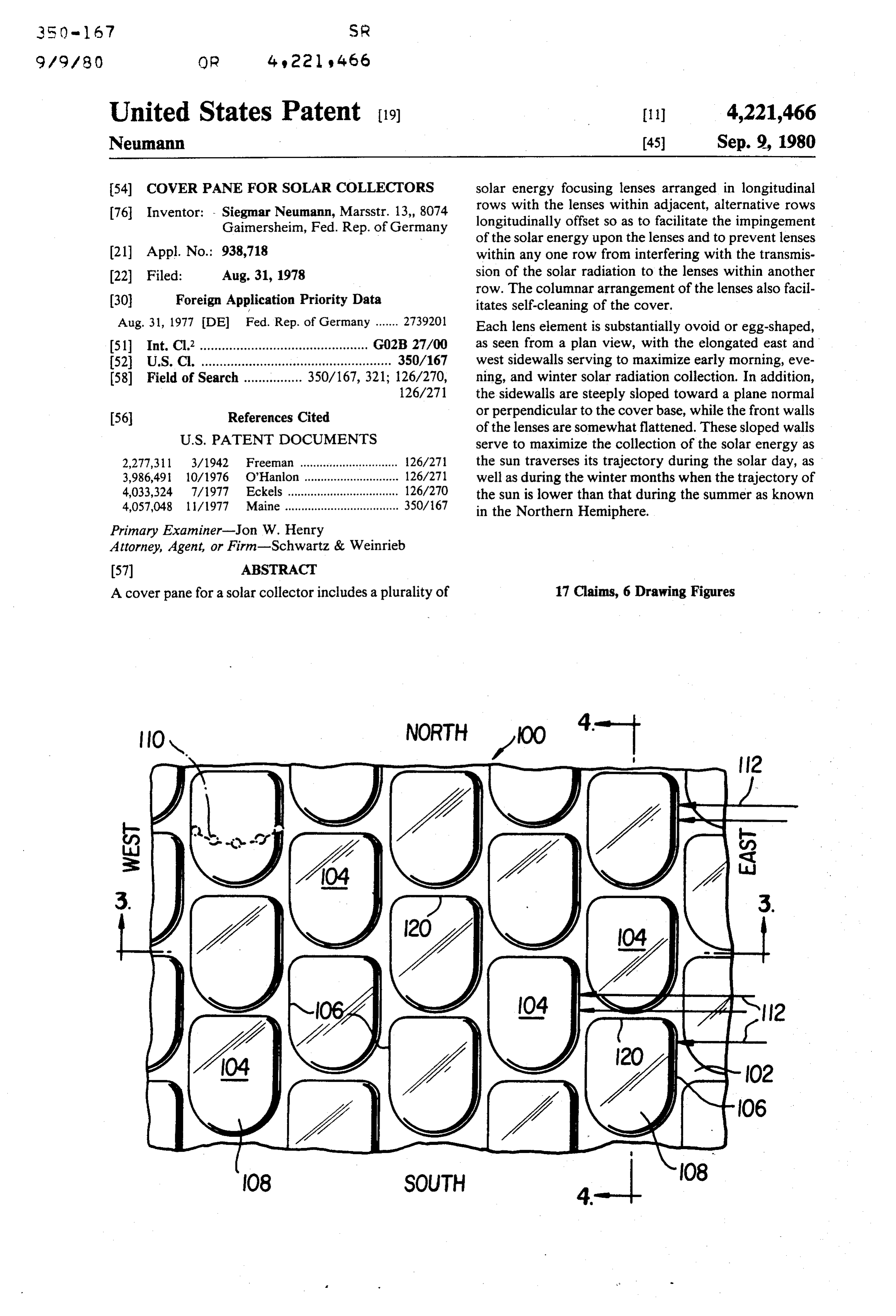
Page 1 — bibliographic record
350 - 67 SR
United States Patent (19)
Neumann
54 COVER PANE FOR SOLAR COLLECTORS
76 Inventor: - Siegmar Neumann, Marsstr. 13, 8074 Gainersheim, Fed. Rep. of Germany
30 Foreign Application Priority Data
51 Int. Cl’.............................................. GO2B 27/00 52 U.S.C. .................................................... 350/167
2,277,311 3/1942 Freeman .............................. 126/271 3,986,49. 10/1976 O’Hanlon ............................. 126/271 4,033,324 7/1977 Eckels .................................. 126/270 4,057,048 11/1977 Maine ................................... 350/167 Primary Examiner-Jon W. Henry
Attorney, Agent, or Firm-Schwartz & Weinrieb
A cover pane for a solar collector includes a plurality of
solar energy focusing lenses arranged in longitudinal rows with the lenses within adjacent, alternative rows longitudinally offset so as to facilitate the impingement of the solar energy upon the lenses and to prevent lenses within any one row from interfering with the transmis sion of the solar radiation to the lenses within another row. The columnar arrangement of the lenses also facil itates self-cleaning of the cover.
Each lens element is substantially ovoid or egg-shaped, as seen from a plan view, with the elongated east and west sidewalls serving to maximize early morning, eve ning, and winter solar radiation collection. In addition, the sidewalls are steeply sloped toward a plane normal or perpendicular to the cover base, while the front walls of the lenses are somewhat flattened. These sloped walls serve to maximize the collection of the solar energy as the sun traverses its trajectory during the solar day, as well as during the winter months when the trajectory of the sun is lower than that during the summer as known in the Northern Hemiphere.
17 Claims, 6 Drawing Figures
Page 2
Drawing sheet — no readable text.
Page 3
Drawing sheet — no readable text.
Page 4
whereby the commercial acceptance of such collectors
COVER PANE FOR SOLAR COLLECTORS is correspondingly low.
FIELD OF THE INVENTION OBJECTS OF THE INVENTION -
The present invention relates generally to solar col 5 Accordingly, it is an object of the present invention lector apparatus, and more particularly to a cover pane to provide a new and improved cover pane for use in for solar collectors. connection with solar collector apparatus.
BACKGROUND OF THE INVENTION
Another object of the present invention is to provide a new and improved cover pane for use in connection
Solar collector apparatus may be broadly classified 10 with solar collector apparatus whereby the aforenoted into two different types, the first of which is the contin drawbacks of conventional solar collector apparatus uously movable type which is designed to continuously will be overcome.
track the movement of the sun throughout the solar Still another object of the present invention is to day, and the second of which is the stationary type 15 provide a new and improved cover pane for use in which is fixedly adjusted with respect to the sun's tra connection with stationary solar collector apparatus jectory for a particular solar season of the year. In both whereby the solar energy absorption or collection effi cases, the particular latitude of the terrestial location at ciency is substantially greater than conventional station which the collector is disposed is also taken into ac ary solar collectors.
COunt. Yet another object of the present invention is to pro In connection with the first type of collector, the 20 vide a new and improved cover pane for use in connec efficiency of such collectors is, as may be expected, tion with stationary solar collector apparatus whereby quite high due to the fact that the collector, being con solar energy may be absorbed or collected throughout tinuously movable along an arc corresponding to the sun's trajectory, is always disposed at an optimum posi the solar day including the critically important early morning and evening hours.
tion relative to the sun whereby the maximum solar 25 A further object of the present invention is to provide energy may be collected. Such collector systems, how a new and improved cover pane for use in connection ever, employ altazimuth motor-driven tracking devices with stationary solar collector apparatus whereby solar which are quite expensive and therefore involve consid erable initial construction and erection expenditures. energy may be absorbed or collected throughout the Consequently, such devices are only normally em 30 solar year including the critically important autumn, winter, and spring solar seasons as experienced in the ployed within sophisticated industrial or commercial Northern Hemisphere.
systems.
In connection with the second type of collector, provide A still further object of the present invention is to while the cost of the systems employing such collectors connection a new and improved cover pane for use in is substantially less than those systems employing solar 35 with stationary solar collector apparatus tracking collectors, the efficiency of these fixed collec which is relatively inexpensive and simplistic in struc tors is quite low. The reason for this may best be appre tre.
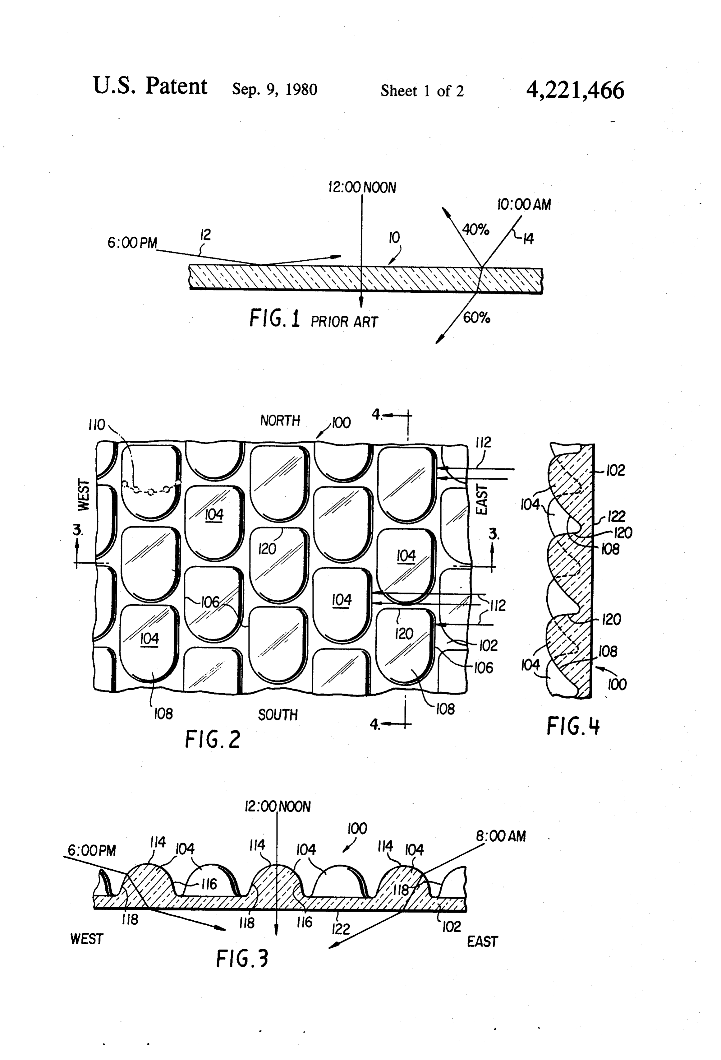
ciated from FIG. 1 of the drawings. As shown in the A yet further object of the present invention is to figure, a conventional solar collector of the stationary provide a new and improved cover pane for use in type is shown as comprising a flat plate type collector. connection with stationary solar collector apparatus An operational characteristic of such conventional col which is readily able to be mass-produced. lectors is that during the early morning and evening An additional object of the present invention is to hours, such as, for example, at 8:00 A.M. or 6:00 P.M., provide a new and improved cover pane for use in the solar rays strike the collector plate, generally indi connection with stationary solar collector apparatus cated by the reference character 10, at an angle of inci 45 which is essentially self-cleaning and therefore easy to dence approximating 10, as shown, for example, by maintain.
solar ray 12. The ray is deflected by the flat plate collec SUMMARY OF THE INVENTION tor, and consequently, solar energy is not transmitted to the absorber structure of the collector apparatus. It has The foregoing and other objectives are achieved in been determined, in fact, that such flat plate collectors 50 accordance with the present invention through the will not normally begin to actually collect a substantial provision of a cover pane, for use in connection with amount of solar energy until the angle of incidence of solar collector apparatus, which comprises a plurality the solar rays approximates 40' as shown for example of solar energy focusing lenses arranged in longitudinal by solar ray 14. Under such circumstances, approxi rows with the lenses within alternative rows longitudi mately 40% of the solar energy is reflected while 60% 55 nally offset with respect to the lenses within the adja of the energy is absorbed. The absorption percentage of cent rows so as to facilitate the impingement of the solar course increases as the angle of incidence approaches energy upon all of the lenses and to prevent the lenses of 90. a particular row from interfering with the lenses within The important consideration to be appreciated by the an adjacent row.
foregoing is that during early morning and evening 60 Each lens element is substantially, ovoid or egg hours, virtually no solar energy is able to be absorbed shaped as seen from a plan view, and this configuration by conventional flat plate, stationary collectors. Similar is seen to be critically important as the elongated east results will likewise prevail during the winter solar and west oriented sidewalls of the lenses serve to maxi season, as experienced in the Northern Hemisphere, due mize the absorption or collection of the solar energy to the fact that the incidence of the solar energy is acute 65 during the early morning and evening hours, as well as in a manner similar to early morning and evening hours. during the winter period of the solar year. In addition, As a result of these circumstances, the efficiency of such the sidewalls are steeply sloped more towards the nor flat plate, stationary collectors is unacceptably low mal or perpendicular than the sidewalls of, for example,
Page 5
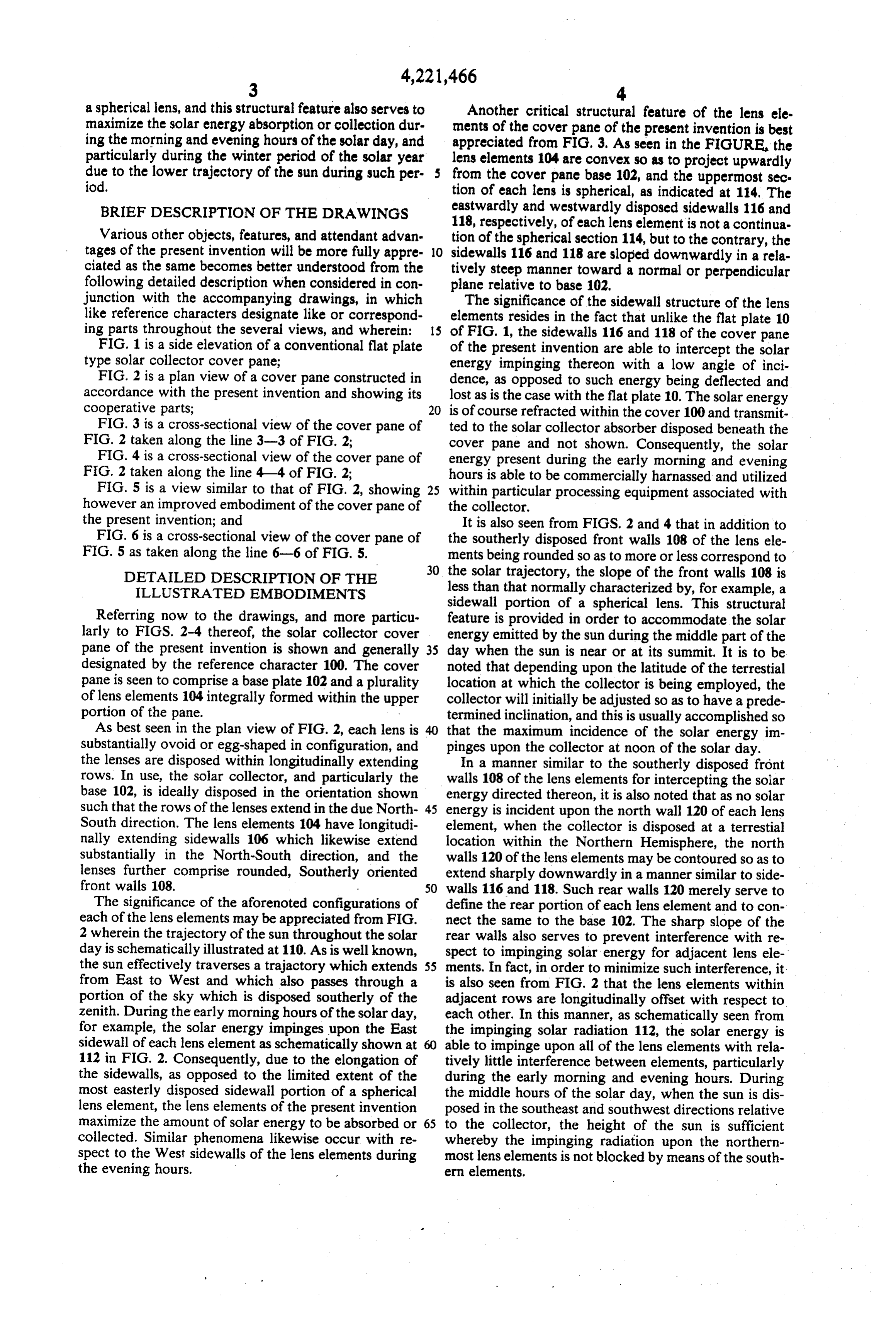
a spherical lens, and this structural feature also serves to Another critical structural feature of the lens ele maximize the solar energy absorption or collection dur ments of the cover pane of the present invention is best ing the morning and evening hours of the solar day, and appreciated from FIG. 3. As seen in the FIGURE, the particularly during the winter period of the solar year lens elements 104 are convex so as to project upwardly due to the lower trajectory of the sun during such per from the cover pane base 102, and the uppermost sec iod. tion of each lens is spherical, as indicated at 114, The BRIEF DESCRIPTION OF THE DRAWINGS eastwardly and westwardly disposed sidewalls 116 and 118, respectively, of each lens element is not a continua
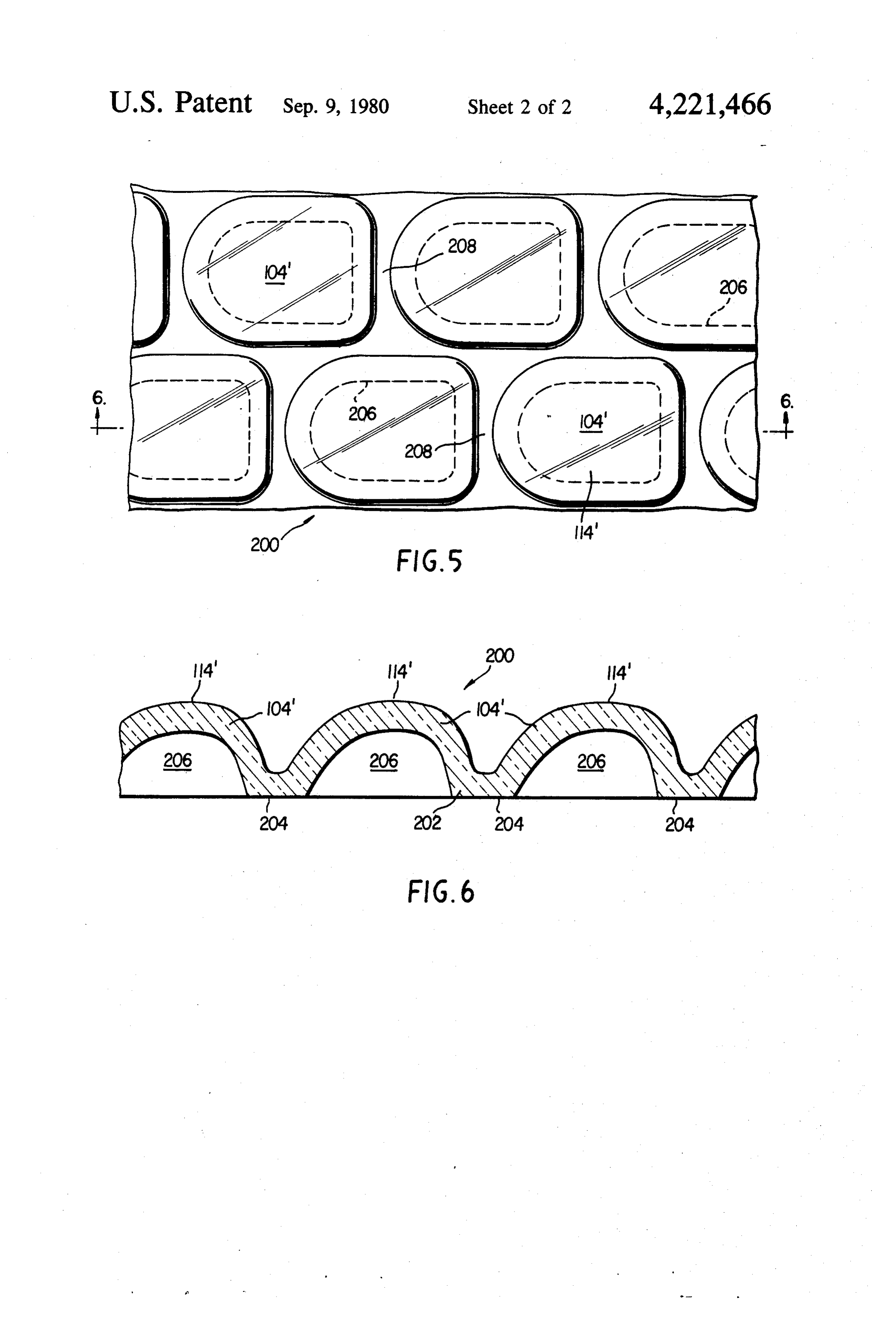
Various other objects, features, and attendant advan tion of the spherical section 114, but to the contrary, the tages of the present invention will be more fully appre 10 sidewalls 116 and 118 are sloped downwardly in a rela ciated as the same becomes better understood from the tively steep manner toward a normal or perpendicular following detailed description when considered in con plane relative to base 102.
junction with the accompanying drawings, in which The significance of the sidewall structure of the lens like reference characters designate like or correspond elements resides in the fact that unlike the flat plate 10 ing parts throughout the several views, and wherein: of FIG. 1, the sidewalls 116 and 118 of the cover pane FIG. 1 is a side elevation of a conventional flat plate of the present invention are able to intercept the solar type solar collector cover pane; energy impinging thereon with a low angle of inci FIG. 2 is a plan view of a cover pane constructed in dence, as opposed to such energy being deflected and accordance with the present invention and showing its lost as is the case with the flat plate 10. The solar energy cooperative parts; 20 is of course refracted within the cover 100 and transmit FIG. 3 is a cross-sectional view of the cover pane of ted to the solar collector absorber disposed beneath the FIG. 2 taken along the line 3-3 of FIG. 2; cover pane and not shown. Consequently, the solar FIG. 4 is a cross-sectional view of the cover pane of energy present during the early morning and evening FIG. 2 taken along the line 4-4 of FIG. 2; hours is able to be commercially harnassed and utilized FIG. 5 is a view similar to that of FIG. 2, showing 25 within particular processing equipment associated with however an improved embodiment of the cover pane of the collector.
the present invention; and It is also seen from FIGS. 2 and 4 that in addition to FIG. 6 is a cross-sectional view of the cover pane of the southerly disposed front walls 108 of the lens ele FIG. 5 as taken along the line 6-6 of FIG. 5. ments being rounded so as to more or less correspond to 30 the solar trajectory, the slope of the front walls 108 is
DETAILED DESCRIPTION OF THE
ILLUSTRATED EMBODIMENTS less than that normally characterized by, for example, a sidewall portion of a spherical lens. This structural
Referring now to the drawings, and more particu feature is provided in order to accommodate the solar larly to FIGS. 2-4 thereof, the solar collector cover energy emitted by the sun during the middle part of the pane of the present invention is shown and generally 35 day when the sun is near or at its summit. It is to be designated by the reference character 100. The cover noted that depending upon the latitude of the terrestial pane is seen to comprise a base plate 102 and a plurality location at which the collector is being employed, the of lens elements 104 integrally formed within the upper collector will initially be adjusted so as to have a prede portion of the pane. termined inclination, and this is usually accomplished so As best seen in the plan view of FIG. 2, each lens is that the maximum incidence of the solar energy im substantially ovoid or egg-shaped in configuration, and pinges upon the collector at noon of the solar day. the lenses are disposed within longitudinally extending In a manner similar to the southerly disposed front rows. In use, the solar collector, and particularly the walls 108 of the lens elements for intercepting the solar base 102, is ideally disposed in the orientation shown energy directed thereon, it is also noted that as no solar such that the rows of the lenses extend in the due North 45 energy is incident upon the north wall 120 of each lens South direction. The lens elements 104 have longitudi element, when the collector is disposed at a terrestial nally extending sidewalls 106 which likewise extend location within the Northern Hemisphere, the north substantially in the North-South direction, and the walls 120 of the lens elements may be contoured so as to lenses further comprise rounded, Southerly oriented extend sharply downwardly in a manner similar to side front walls 108. 50 walls 116 and 118. Such rear walls 120 merely serve to The significance of the aforenoted configurations of define the rear portion of each lens element and to con each of the lens elements may be appreciated from FIG. nect the same to the base 102. The sharp slope of the 2 wherein the trajectory of the sun throughout the solar rear walls also serves to prevent interference with re day is schematically illustrated at 110. As is well known, spect to impinging solar energy for adjacent lens ele the sun effectively traverses a trajactory which extends 55 ments. In fact, in order to minimize such interference, it from East to West and which also passes through a is also seen from FIG. 2 that the lens elements within portion of the sky which is disposed southerly of the adjacent rows are longitudinally offset with respect to zenith. During the early morning hours of the solar day, each other. In this manner, as schematically seen from for example, the solar energy impinges upon the East the impinging solar radiation 112, the solar energy is sidewall of each lens element as schematically shown at 60 able to impinge upon all of the lens elements with rela 112 in FIG. 2. Consequently, due to the elongation of tively little interference between elements, particularly the sidewalls, as opposed to the limited extent of the during the early morning and evening hours. During most easterly disposed sidewall portion of a spherical the middle hours of the solar day, when the sun is dis lens element, the lens elements of the present invention posed in the southeast and southwest directions relative maximize the amount of solar energy to be absorbed or 65 to the collector, the height of the sun is sufficient collected. Similar phenomena likewise occur with re whereby the impinging radiation upon the northern spect to the West sidewalls of the lens elements during most lens elements is not blocked by means of the south the evening hours. ern elements.
Page 6
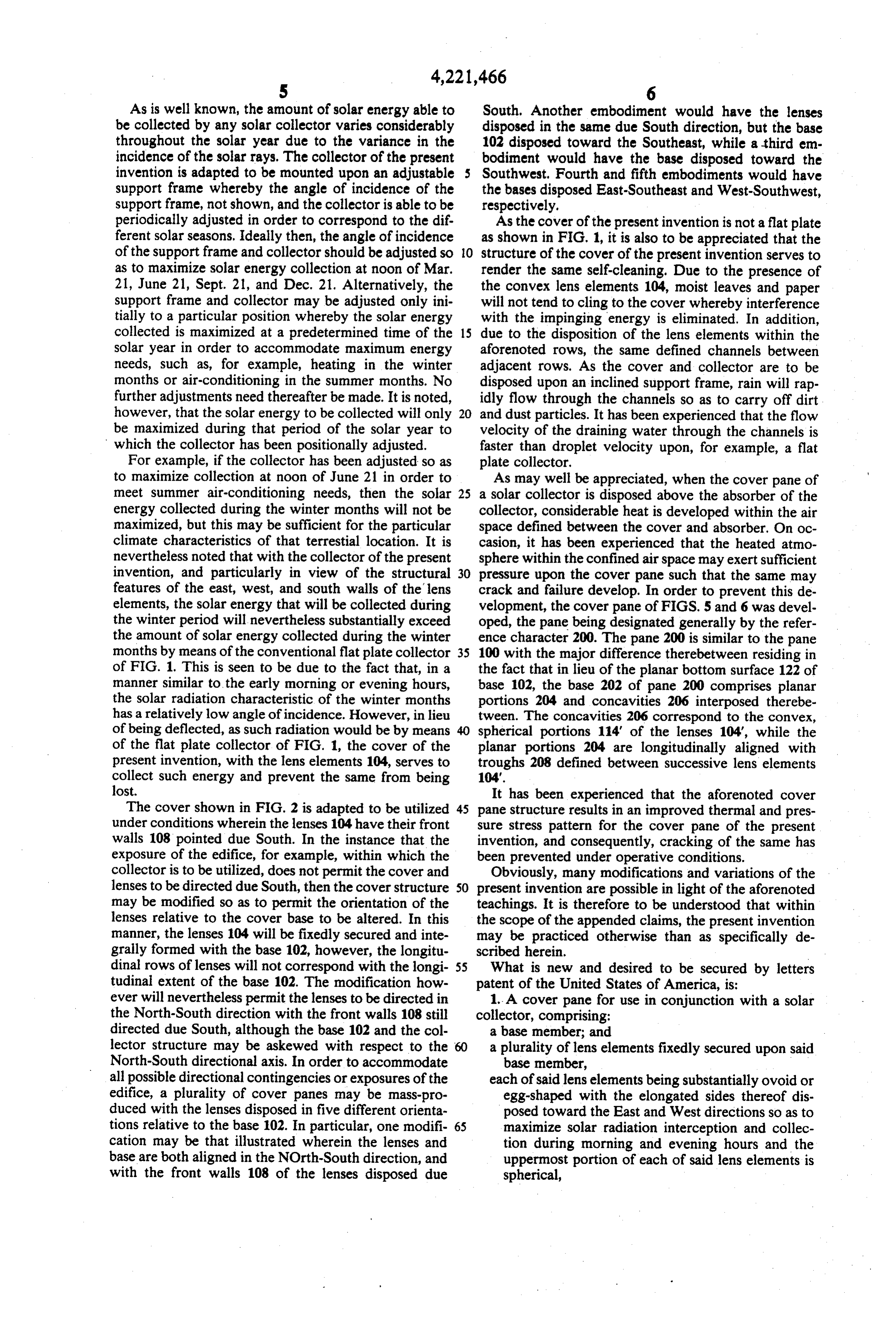
As is well known, the amount of solar energy able to South. Another embodiment would have the lenses be collected by any solar collector varies considerably disposed in the same due South direction, but the base throughout the solar year due to the variance in the 102 disposed toward the Southeast, while a third em incidence of the solar rays. The collector of the present bodiment would have the base disposed toward the invention is adapted to be mounted upon an adjustable s Southwest, Fourth and fifth embodiments would have support frame whereby the angle of incidence of the the bases disposed East-Southeast and West-Southwest, support frame, not shown, and the collector is able to be respectively.
periodically adjusted in order to correspond to the dif As the cover of the present invention is not a flat plate ferent solar seasons. Ideally then, the angle of incidence as shown in FIG. 1, it is also to be appreciated that the of the support frame and collector should be adjusted so O structure of the cover of the present invention serves to as to maximize solar energy collection at noon of Mar. render the same self-cleaning. Due to the presence of 21, June 21, Sept. 21, and Dec. 21. Alternatively, the the convex lens elements 104, moist leaves and paper support frame and collector may be adjusted only ini will not tend to cling to the cover whereby interference tially to a particular position whereby the solar energy with the impinging energy is eliminated. In addition, collected is maximized at a predetermined time of the 15 due to the disposition of the lens elements within the solar year in order to accommodate maximum energy aforenoted rows, the same defined channels between needs, such as, for example, heating in the winter adjacent rows. As the cover and collector are to be months or air-conditioning in the summer months. No disposed upon an inclined support frame, rain will rap further adjustments need thereafter be made. It is noted, idly flow through the channels so as to carry off dirt however, that the solar energy to be collected will only 20 and dust particles. It has been experienced that the flow be maximized during that period of the solar year to velocity of the draining water through the channels is which the collector has been positionally adjusted. faster than droplet velocity upon, for example, a flat For example, if the collector has been adjusted so as plate collector.
to maximize collection at noon of June 21 in order to As may well be appreciated, when the cover pane of meet summer air-conditioning needs, then the solar 25 a solar collector is disposed above the absorber of the energy collected during the winter months will not be collector, considerable heat is developed within the air maximized, but this may be sufficient for the particular space defined between the cover and absorber. On oc climate characteristics of that terrestial location. It is casion, it has been experienced that the heated atmo nevertheless noted that with the collector of the present sphere within the confined air space may exert sufficient invention, and particularly in view of the structural 30 pressure upon the cover pane such that the same may features of the east, west, and south walls of the lens crack and failure develop. In order to prevent this de elements, the solar energy that will be collected during velopment, the cover pane of FIGS. 5 and 6 was devel the winter period will nevertheless substantially exceed oped, the pane being designated generally by the refer the amount of solar energy collected during the winter ence character 200. The pane 200 is similar to the pane months by means of the conventional flat plate collector 35 100 with the major difference therebetween residing in of FIG. 1. This is seen to be due to the fact that, in a the fact that in lieu of the planar bottom surface 122 of manner similar to the early morning or evening hours, base 102, the base 202 of pane 200 comprises planar the solar radiation characteristic of the winter months portions 204 and concavities 206 interposed therebe has a relatively low angle of incidence. However, in lieu tween. The concavities 206 correspond to the convex, of being deflected, as such radiation would be by means spherical portions 114 of the lenses 104, while the of the flat plate collector of FIG. 1, the cover of the planar portions 204 are longitudinally aligned with present invention, with the lens elements 104, serves to troughs 208 defined between successive lens elements collect such energy and prevent the same from being 104".
lost. It has been experienced that the aforenoted cover The cover shown in FIG. 2 is adapted to be utilized 45 pane structure results in an improved thermal and pres under conditions wherein the lenses 104 have their front sure stress pattern for the cover pane of the present walls 108 pointed due South. In the instance that the invention, and consequently, cracking of the same has exposure of the edifice, for example, within which the been prevented under operative conditions. collector is to be utilized, does not permit the cover and Obviously, many modifications and variations of the lenses to be directed due South, then the cover structure 50 present invention are possible in light of the aforenoted may be modified so as to permit the orientation of the teachings. It is therefore to be understood that within lenses relative to the cover base to be altered. In this the scope of the appended claims, the present invention manner, the lenses 104 will be fixedly secured and inte may be practiced otherwise than as specifically de grally formed with the base 102, however, the longitu scribed herein.
dinal rows of lenses will not correspond with the longi 55 What is new and desired to be secured by letters tudinal extent of the base 102. The modification how patent of the United States of America, is: ever will nevertheless permit the lenses to be directed in 1. A cover pane for use in conjunction with a solar the North-South direction with the front walls 108 still collector, comprising:
directed due South, although the base 102 and the col a base member; and lector structure may be askewed with respect to the 60 a plurality of lens elements fixedly secured upon said North-South directional axis. In order to accommodate base member, all possible directional contingencies or exposures of the each of said lens elements being substantially ovoid or edifice, a plurality of cover panes may be mass-pro egg-shaped with the elongated sides thereof dis duced with the lenses disposed in five different orienta posed toward the East and West directions so as to tions relative to the base 102. In particular, one modifi maximize solar radiation interception and collec cation may be that illustrated wherein the lenses and tion during morning and evening hours and the base are both aligned in the NOrth-South direction, and uppermost portion of each of said lens elements is with the front walls 108 of the lenses disposed due spherical,
Page 7
the front wall of each of said lens elements is rounded a base member; and and disposed toward the South direction, and a plurality of lens elements fixedly secured upon said the slope of said front wall of each of said lens ele base member, - ments is shallower than that of said spherical por each of said lens elements being substantially ovoid or tion of each of said lens elements so as to maximize egg-shaped with the elongated sides thereof dis the solar radiation interception and collection dur posed toward the East and West directions so as to ing the middle hours of the solar day. maximize solar radiation interception and collec 2. The cover pane as set forth in claim 1, wherein: tion during morning and evening hours, each of said lens elements comprises a convex struc the uppermost portion of each of said lens elements ture projecting upwardly from said base. 10 defining said East and West sides of each of said 3. The cover pane as set forth in claim 2, wherein: lens elements is sloped sharply downwardly so as the front wall of each of said lens elements is rounded to deviate from the spherical curvature of said and disposed toward the South direction; and uppermost portion of each of said lens elements and the slope of said front wall of each of said lens ele approach a plane normal or perpendicular to said ments is shallower than that of said spherical por 15 base, tion of each of said lens elements so as to maximize whereby the solar radiation interception and collec the solar radiation interception and collection dur tion is maximized still further. ing the middle hours of the solar day. 11. The cover pane as set forth in claim 10, wherein: 4. The cover pane as set forth in claim 1, wherein: each of said lens elements comorises a convex struc the Northerly directed walls of each of said lens ele 20 ture projecting upwardly from said base. ments is sloped sharply downwardly toward said 12. The cover pane as set forth in claim 11, wherein: base so as to minimize solar radiation impingement the front wall of each of said lens elements is rounded interference between said lens elements. and disposed toward the South direction; and 5. The cover pane as set forth in claim 1, wherein: the slope of said front wall of each of said lens ele said lens elements are disposed in longitudinally ex 25 ments is shallower than that of said spherical por tending rows. tion of each of said lens elements so as to maximize 6. The cover pane as set forth in claim 5, wherein: the solar radiation interception and collection dur the lens elements within adjacent rows are longitudi ing the middle hours of the solar day. nally offset with respect to the elements within 13. The cover pane as set forth in claim 10, wherein: adjacent rows so as to minimize solar radiation 30 the Northerly directed walls of each of said lens ele impingement interference between said lens ele ments is sloped sharply downwardly toward said ments. base so as to minimize solar radiation impringement 7. The cover pane as set forth in claim 5, wherein: interference between said lens elements. said rows of lens elements define channels therebe 14. The cover pane as set forth in claim 10, wherein: tween for conducting rainwater therethrough, 35 said lens elements are disposed longitudinally extend whereby said rainwater drained from said cover pane ing rows.
removes entrained dirt and dust particles thereby 15. The cover pane as set forth in claim 14, wherein: rendering said pane self-cleaning. the lens elements within adjacent rows are longitudi 8. The cover pane as set forth in claim 2, wherein: nally offset with respect to the elements within the undersurface of said base member comprises a adjacent rows so as to minimize solar radiation plurality of concavities which correspond to the impingement interference between said lens ele convex configurations of said lens elements so as to ents.
establish favorable thermal and pressure stress 16. The cover pane as set forth in claim 14, wherein: characteristics within said pane so as to prevent said rows of lens elements define channels therebe failure thereof. 45 tween for conducting rainwater therethrough, 9. The cover pane as set forth in claim 2, wherein: whereby said rainwater drained from said cover pane the sidewalls of each of said lens elements defining removes entrained dirt and dust particles thereby said East and West sides of each of said lens ele rendering said pane self-cleaning. ments is sloped sharply downwardly so as to devi 17. The cover pane as set forth in claim 11, wherein: ate from the spherical curvature of said uppermost 50 the undersurface of said base member comprises a portion of each of said lens elements and approach plurality of concavities which correspond to the a plane normal or perpendicular to said base, convex configurations of said lens elements so as to whereby the solar radiation interception and collec establish favorable thermal and pressure stress tion is maximized still further. characteristics within said pane so as to prevent 10. A cover pane for use in conjunction with a solar 55 failure thereof.
collector, comprising: k s K t
Provenance
- Collection
- Patents citing this work
- Pages
- 7
- Method
- pdftotext (the PDF's own text layer) + pdftoppm 300dpi page scans
- Patent office record
- patents.google.com →
- Source
- Google Patents citing-documents table
- Assignee
- Siegmar Neumann
- Published
- 1980-09-09
- Transcribed from
- patentimages.storage.googleapis.com →