patent · US4184461
Acceleration enrichment for closed loop control systems
22 January 1980
Page 1 — bibliographic record
United States Patent (19) 11 4,184,461 Leung 45 Jan. 22, 1980 54 ACCELERATION ENRICHMENT FOR FOREIGN PATENT DOCUMENTS
CLOSED LOOP CONTROL SYSTEMS
75) Inventor: Chun K. Leung, Farmington Hills, Primary Examiner-Charles J. Myhre Mich.
Assistant Examiner-Andrew M. Dolinar 73 Assignee: The Bendix Corporation, Southfield, Attorney, Agent, or Firm-William A. Marvin; Russel C.
21 Appl. No.: 836,333 An acceleration enrichment feature for a closed loop 22 Filed: Sep. 26, 1977 fuel management system controlling the air/fuel mix ture delivered to an internal combustion engine to regu 51 int. C.? .......................... F02D 5/00; F02M 7/06 late the roughness of the engine at a predetermined 52 U.S. Cl. ......................... 123/32 EH; 123/32 EA; level. The enrichment feature provides increased fuel to 123/32 ED; 123/119 EC the engine for operator induced transient conditions 58 Field of Search ......... 123/32 EH, 32 EL, 32 EJ, proportionately by sensing the rate of change of throttle 123/32 ED, 32 EA, 32 EE, 119 EC angle. A throttle angle position signal is modified by circuitry providing a transfer function that introduces a 56) References Cited lag term into the throttle angle position signal which differentiating the signal to determine the rate of change
3,661,126 5/1972 Baxendale ....................... 123/32 EH signal is additionally corrected by the amount of rough 3,673,989 7/1972 Aono et al. ......... ... 23/32 EH ness sensed by the closed loop control and enriched for 3,759,231 9/1973 Endo ............... ... 23/32 EH rough operations of the engine beyond a threshold and 3,786,788 1/1974. Suda et al. ...... ... 123/32 EA leaned for smooth operations of the engine. Accelera 3,789,816 2/1974 Taplin et al. ... ... .23/32 EA tion enrichment pulses of a frequency dependent on the 4,010,717 3/1977 Taplin ............. ... 123/32 EH magnitude of the corrected throttle position signal are 4,048,964 9/1977 Kissel .............. ... 23/32 EA then combined with the basic fuel injection pulses of the 4,075,982 2/1978 Asano et al. ........ ... 123/32 EL closed loop fuel management system to provide a de 4,077,364 3/1978 Aoki ............ ... 23/32 EH 4,079,711 3/1978 Hattori et al. ... 123A32EE sired A/F ratio during operator induced transients, 4,088,095 5/1978 Aono ....................... ... 123/32 EE 4,112,879 9/1978 Assenheimer et al. ......... 123/32 EH 20 Claims, 8 Drawing Figures
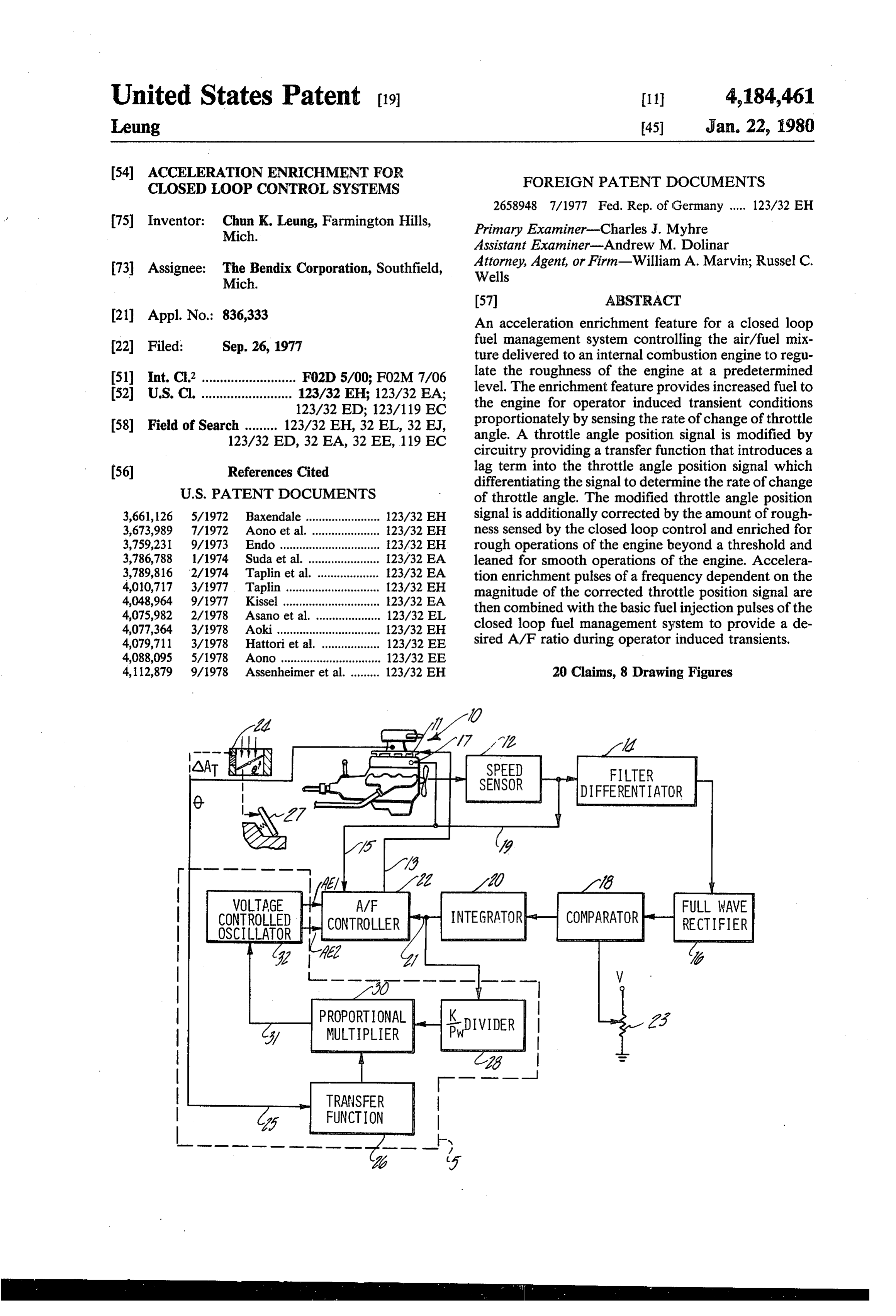
SPEED
DIFFERENTIATOR
WOLTAGE FULL WAVE
CONTROLED
OSCILLATOR
INTEGRATOR COMPARATOR RECTIFIER
BDIVIDER
MULTIPLIER
TRANSFER
FUNCTION
Page 2
Drawing sheet — no readable text.
Page 3
Drawing sheet — no readable text.
Page 4
Drawing sheet — no readable text.
Page 5
some systems the closed loop control is cut out during
ACCELERATION ENRICHMENT FOR CLOSED transient conditions, the system may operate far from LOOP CONTROL SYSTEMS the desired operating point causing emissions to rise
BACKGROUND OF THE INVENTION
considerably or the before-mentioned driveability prob 5 lems. The closed loop integral controllers will return to 1. Field of the Invention the desired operating point at some integration rate The invention pertains generally to the field of elec after cessation of the transient but the further the tran tronic fuel management systems for internal combustion sient has moved the system from the desired point, the engines and is more particularly directed to an accelera 10 longer it will take to return it. For example, with a tion enrichment feature during operator induced tran system operating rich with the integral controller still sients for closed loop fuel management systems. heading in the rich direction, an acceleration enrich 2. Prior Art ment transient will shift the operation substantially from There has been recognized in the electronic fuel in that desired.
jection art the need for fuel enrichment during certain 15 Thus, a better method can be devised where the ac transient conditions. Of the most important transients celeration enrichment is not only a function of the pa are those that are operator or driver induced and com rameters that are directly changed because of operator monly termed accelerations or decelerations. The induced transient conditions but also is a function of the driveability of the automobile will be detrimentally instantaneous operating condition of the engine. Vary effected if the fuel management system does not provide ing the acceleration enrichment to increase the amount the right air/fuel mixture during these conditions. Elec 20 enrichment during lean engine operations and de tronic control units for electronic fuel injection systems of crease the amount of enrichment during rich engine today normally have auxiliary circuits of various types operations for enriching the fuel mixture during acceleration and to the ideal.will produce a system more closely related decreasing or terminating the enrichment during decel One of the more advantageous types of closed loop
Generally, the auxiliary circuits have a sensing means sensor forcontroller integral systems in the prior art uses an O2 detecting rich or lean excursions of the air/ffor determining that enrichment is necessary and for uel calculating an amount of enrichment based on the haustratio by sensing the presence of oxygen in the ex gases. These systems usually operate at an average change or rate of change in some parameter such as air/fuel ratio that is stoichiometric or slightly offset manifold pressure, throttle angle, RPM, etc. These pa 30 from that point. An acceleration enrichment feature rameters or variables and combinations thereof provide sensitive a direct method of sensing the transient conditions and to the instantaneous air/fuel ratio will assist in their magnitudes are substantially proportional to the maintaining the emission levels in these systems. enrichment needed. Another of the more advantageous types of closed The auxiliary circuits then commonly lengthen or 35 loop integral controllers is one which operates with a provide additional acceleration enrichment (AE) pulses mixture so lean that the engine will just begin to run to the base fuel pulse produced by the fuel management rough. The roughness threshold or average air/fuel system. According to this operation, the main fuel man ratio operating point for this system is set by the drivea agement system sets a desired air/fuel ratio that is cor bility criteria of the auto and acceleration enrichment rect for nontransient conditions and the auxiliary cir for transients is necessitated to maintain this point. An cuits provide the enrichment needed for the proper acceleration enrichment feature sensitive to the instan air/fuel mixture during transient condition. taneous air/fuel ratio is therefore more important to this While this theory of operation is correct in the macro type of system because excursions for any length of time sense in that many main fuel management systems do to the lean side of the threshold will be immediately felt provide a desired average air/fuel ratio, the theory 45 by the operator as hesitations, roughness, or even stalls. breaks down in the micro sense for closed loop systems. Excursions on the rich side for any length of time will These systems provide means for correction toward the be defeating one of the primary purpose of the system, desired air/fuel ratio or operating point and are continu that of fuel economy.
ally hunting for that value. It is generally understood SUMMARY OF THE INVENTION that with modern closed loop integral control, most of 50 the system operation is not exactly at the desired ratio. An acceleration enrichment feature for closed loop At any instant, the air/fuel ratio maybe more or less fuel management systems is provided according to the than the desired value and it is only the summation or invention. The enrichment feature is generated propor average of the instantaneous points that produce a de tionately as a function of the combination of a change in sired fuel ratio. 55 an operator induced variable and a variable which is Therefore, it is seen that if the auxiliary circuit pro representative of the instantaneous air/fuel ratio from vides acceleration enrichment based only on the tran the operating condition of the engine. sient variables when injecting additional or lengthening In the preferred embodiment, the acceleration enrich the basic pulse width during air/fuel ratios that are rich ment feature includes throttle sensing means for sensing the combination will be excessively rich and conversely 60 the rate of change of throttle angle due to operator when injecting pulses or modifying pulse width during induced transients. The rate of change of throttle angle lean excursions the combination will not be rich will not only be directly proportional to the amount of enough. These differences between the ideal response acceleration enrichment desired by the operator but and the actual response of the air/fuel ratio will tend to also is the incipient indicator of the beginning of an average out for very long accelerations but at the ex 65 acceleration and therefore a primary representation of pense of smooth and instantaneous accelerations. the need for enrichment. By sensing the rate of change Moreover, when the actual operating conditions of of throttle angle as the operator induced variable, the the engine are not accounted for, particularly when in system will respond quickly and smoothly to the tran
Page 6
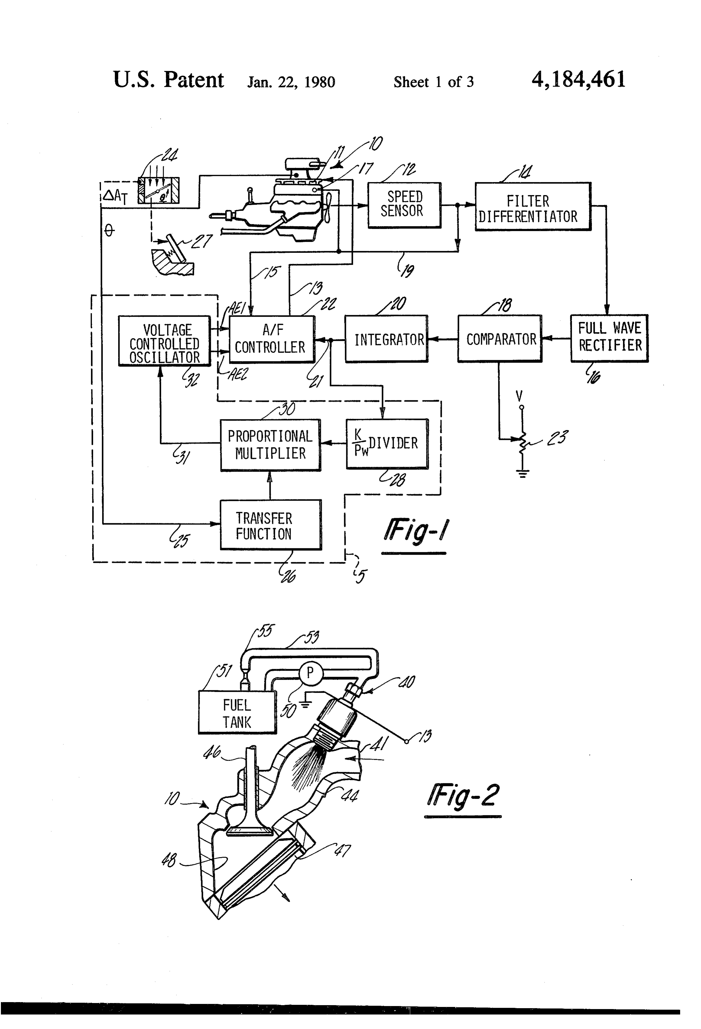
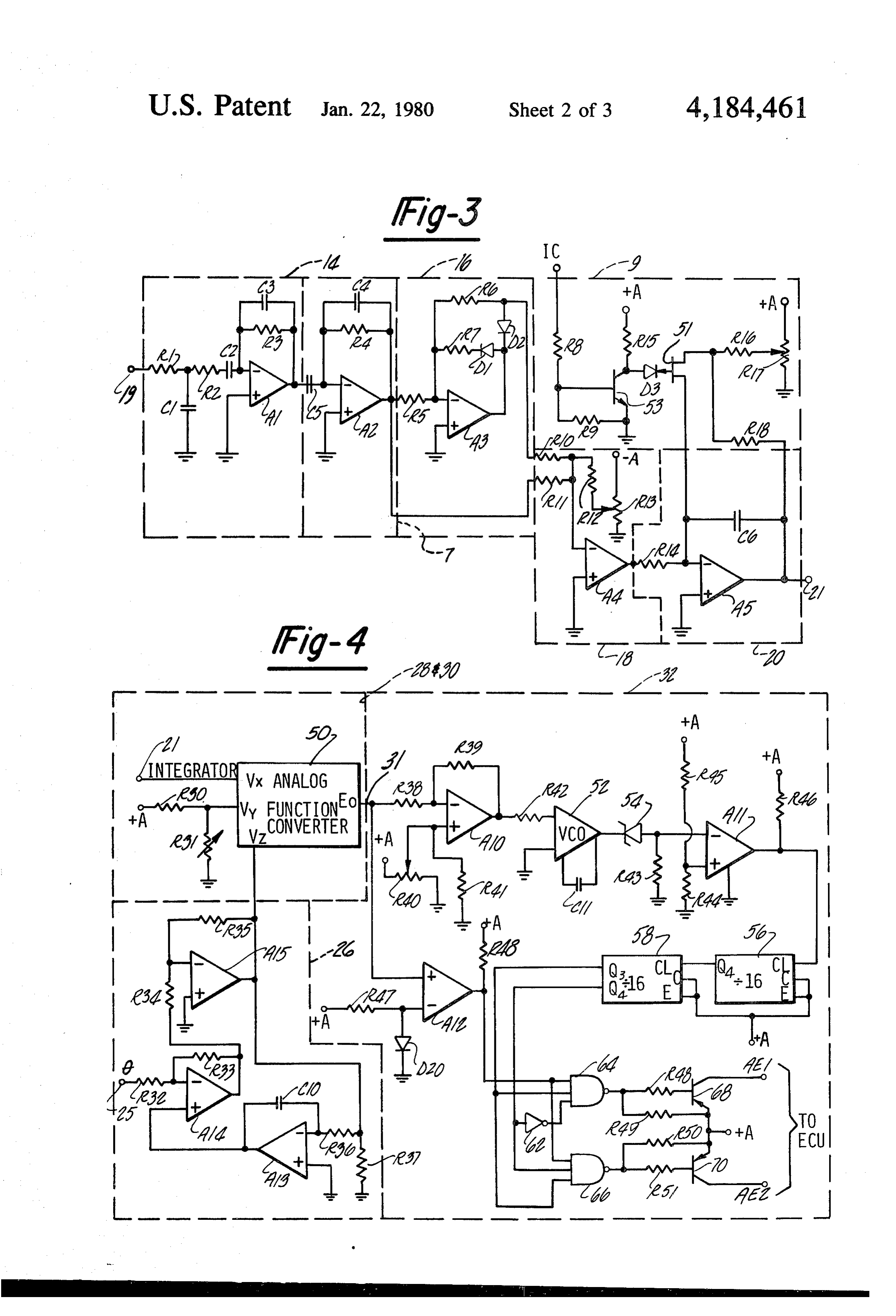
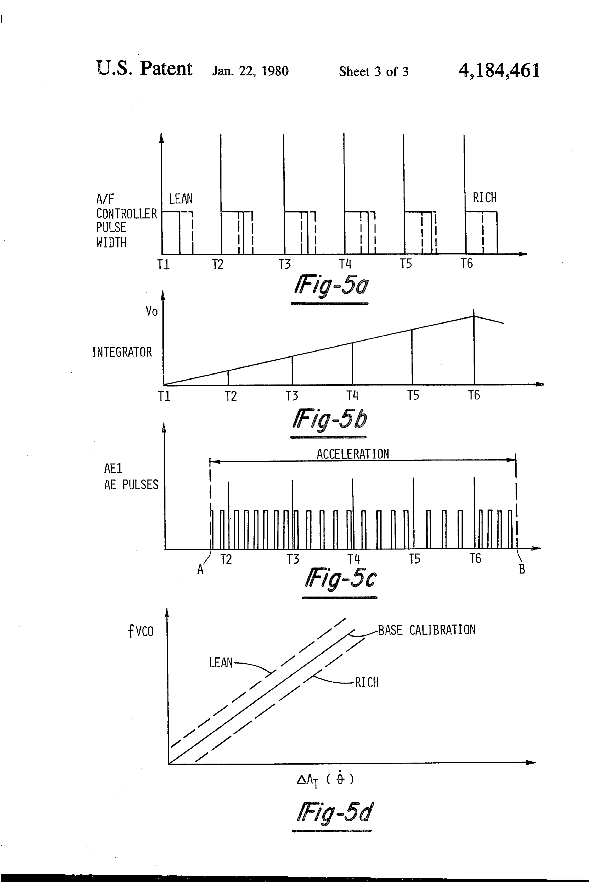
sients. The throttle sensing means generates a throttle FIG. 2 is a partially sectioned, partially schematic signal proportional to the sensed rate of change, the view of an electronic fuel injector for the electronic fuel magnitude of which is representative of the amount of injection means of the closed loop fuel management enrichment or acceleration desired by the operator. system illustrated in FIG. 1. The acceleration enrichment feature further includes FIG. 3 is a detailed electrical schematic view of cir sensing means for sensing the roughness parameter of a cuitry comprising the integral roughness control loop closed loop integral roughness controller. This rough for the fuel management system illustrated in FIG. 1. ness variable, the magnitude of which is representative FIG. 4 is a detailed electrical schematic view of cir of the integral excursions to the rich and lean side of a cuitry comprising the acceleration enrichment feature roughness threshold, will be an indication of the instan 10 for the fuel management system illustrated in FIG. 1. taneous air/fuel ratio of the operating engine. The sens FIG. 5a-d are waveform diagrams of various signals ing means generates a roughness signal proportional to found throughout the fuel management system illus the roughness sensed, the magnitude of which is there trated in FIG. 1.
fore indicative of the instantaneous air/fuel ratio of the DETALEO DESCRIPTION engine. 15
The roughness signal or the instantaneous A/F ratio With reference to FIG. 1 there is shown an internal and the throttle signal or the operator induced variable combustion engine 10, including a fuel injection means are combined in combinational circuitry included in an 11, that is operable to deliver a fuel flow in a controlla acceleration enrichment circuit to provide an increase ble way and thereby maintain a desired relationship to in the amount of acceleration enrichment for lean excur 20 air flow. The fuel injection means 11 is generally sions of the A/F ratio from the desired operating point adapted to vary the air/fuel ratio in response to differ and to decrease the amount of acceleration enrichment ent pulse widths from an air/fuel controller 22 which is for rich excursions of the A/F ratio from the desired operably connected via conductor bus 13. operating point. The combinational circuitry then pro The air/fuel controller 22 can be of the type known in vides an AE signal dependent upon the operator in 25 the art for controlling the length of the fuel injection duced variable and the instantaneous operating condi period by using one or more engine dependent parame tion of the engine. The acceleration enrichment circuit ters to either vary the point at which the injection per is responsive to the acceleration enrichment signal to iod commences or to vary the point at which such injec provide fuel enrichment proportionately to the signal tion period terminates. The air/fuel controller 22 of the when an acceleration is sensed. 30 presently preferred embodiment comprises a suitable Therefore, it is a primary object of the invention to pulse train generating device which maybe of a type provide proportional acceleration enrichment for a disclosed in commonly assigned U.S. Pat. No. 3,734,068 closed loop integral controller of a fuel management issued May 22, 1973 to Junuthula N. Reddy and entitled system which is dependent upon a transient condition in "Fuel Injection Control System', the disclosure of the control of the engine and the instantaneous operat 35 which is herein expressely incorporated by reference. ing condition of the engine. As described in further detail in the indicated Reddy Accordingly, another object of the invention is to patent, the air/fuel controller 22 generates a pulse train provide an acceleration enrichment feature dependent of specially shaped voltage vs. time signals with each upon the instantaneous air/fuel ratio of the engine. pulse having a specially shaped beginning portion for Still another object of the invention is to provide the determining the commencement of each injection per acceleration enrichment feature proportionately to the iod in accordance with engine speed and a constant rate of change of throttle angle to sense operator in sloped ramp portion for terminating each injection duced transients incipiently for facile and rapid system pulse when the ramp portion intercepts a predetermined response. reference level related to air flow. Yet another object of the invention is to provide an 45 To receive such air flow and speed dependent intelli acceleration enrichment feature dependent upon a func gence, the air/fuel controller 22 is connected by a con tion of a roughness parameter to indicate instantaneous ductor 15 through a sensor 17 for sensing the air flow or air/fuel ratio. parameter related thereto such as the manifold air pres Yet still another object of the invention pertains to sure. Further, the air/fuel controller 22 is connected improving the driveability of a fuel management system 50 electrically to a speed sensor or tachometer 12 via con using a closed loop integral roughness controller during ductor 19 to provide another parameter for input to the operator induced transients. air/fuel controller via conductor 15. The speed sensor Still another object of the invention is to provide an 12 in the present application comprises a toothed ta acceleration enrichment feature having improved chometer wheel suitably coupled to a crankshaft driven driveability for a closed loop roughness system during 55 member (not shown) of the internal combustion engine operator induced transients without sacrificing fuel 12 such as a fly wheel, ring gear or pulley thereof. Other economy. suitable parameters of the operating engine can also be These and other objects, features, and aspects of the sensed and utilized in this manner. invention will be better understood from a reading of Using the engine speed and the air flow intelligence the following detailed description when taken in con 60 thus provided air fuel controller 22 operates to modify junction with the appended drawings wherein: the duration of the pulse injection period so as to main
DESCRIPTION OF THE DRAWINGS
tain a desired relationship between the air flow and the fuel flow, where such desired relationship varies from
FIG. is a system block diagram of a closed loop fuel an air/fuel ratio as low as 9:1 during cold engine starting management system with integral control, responsive to 65 conditions to slightly above the stoichiometric ratio of the level of roughness of an internal combustion engine, about 14.8:1 on completion of engine warm-up. It is and including an acceleration enrichment feature in evident that lower or higher air ratios can be used if accordance with the invention. necessary.
Page 7
FIG. 2 shows a partially schematic, partially broken Ser. No. 249,440 filed on Apr. 24, 1972, now aban away view of one of the plurality of injecting devices 40 doned, in the name of Taplin et al and entitled "Serge utilized by the fuel injector means 11 and controlled by Sensor Apparatus for a Prime Mover,' the disclosure of the variable pulse width of the A/F controller 22. The which application is herein expressly incorporated by fuel injector 40 is of the electromagnetic solenoid valve reference.
type and is located by threadably mounting it within The differentiator 14 receives the speed signal from upwardly canted boss of an input manifold 44 of the the sensor 12 and further attentuates frequencies outside engine 10. The injector 40 receives a supply of fuel from a desired band and differentiates the remaining signal to a fuel tank 5 acting as a reservoir through a filter ori generate a roughness signal which varies with at least fice 55 and fuel line 53, which is continually pressurized O the first derivative of the speed signal. Higher ordered and recirculated by a pump 50. derivatives maybe used and any sensor capable of deliv This continuous flow provides the source of fuel ering an electrical signal responsive to or indicative of needed for injection when the device 40 is energized via the roughness of the internal combustion engine 12 is one of the injector conductors 13. A variable length compatible with the disclosed feedback control loop. pulse on the injector conductor 13 will cause an open 15 The derivative signal is passed through the full-wave ing of the solenoid actuated valve and a consequent rectifier 16 to develop a voltage level which includes atomizing spary of fuel into the intake manifold 44 positive accelerations as well as negative decelerations which also has a port 41 communicating to the throttle in the changing speed characteristic of the engine. The body for inletting air to be mixed with the injected fuel. voltage level from the full-wave rectifier 16 is input to This injection, of course, occurs in synchronism with 20 the comparator 18 and a suitable source of reference the opening or just before the opening of the intake voltage V is used to compare the output of the rectifier valve 46 during the downstroke of a piston 47 of the 16 with a predeterinined amount of roughness from engine 10. The air/fuel mixture then is drawn into the threshold 23.
head of the combustion chamber 48 where it will be If the engine is indicating more roughness than the combusted as is conventional and thereafter exhausted. 25 amount of roughness set in the threshold, then the com The fuel injector means 11 shown usually has a plu parator 18 produces a comparison signal of one polarity rality of the injectors 40, generally one per each single or level and conversely when the roughness signal is cylinder, with an eight-cylinder engine having two lower than the threshold, the comparator will produce alternating banks of four injectors. Normal operation the opposite polarity or a different level. This compari has all injectors of each bank fired in synchronism and 30 son signal is communicated to the integrator 20 which thus two phased pulse trains of the variable width pulses provides an integral ramp from the levels and thus gen from the air/fuel controller 22 will be provided to inject erates an air/fuel ratio change command that is supplied the fuel into the engine 10. to the air/fuel controller 22. This integral command Returning now to the initial drawing, the fuel man causes the controller to either continually shorten the agement system illustrated in FIG. 1 also comprises a 35 period of the fuel injection pulse and thereby increase roughness control loop which generates and applies to the air/fuel ratio towards a lean limit, as long as the the air/fuel controller 22 an air/fuel ratio change com output of the comparator 18 is of the first polarity, or to mand via conductor 2 that normally decreases the fuel otherwise increase the period of the injection pulse to injection period so as to increase the air/fuel ratio until decrease the air/fuel ratio away from its lean limit as the engine is biased to a limit so lean that the engine just long as the output of the comparator is of the other begins to run rough. The roughness control loop then polarity.
responds to this incipient roughness by momentarily The magnitude of the threshold reference provided decreasing the air/fuel ratio change command and by the comparator is selected to correspond with the thereby enriching the air/fuel ratio. Such an air/fuel level of engine roughness at which the air/fuel mixture ratio change command increases the fuel injection per 45 has made it as lean as possible to the point that the iod by causing the ramp of the controller generated formation of exhaust gas constituent such as HC and pulse train to intercept the reference voltage later as CO is minimized without the driveability of a particular might be affected either by decreasing the slope of the vehicle becoming unacceptable. To effect this tradeoff ramp portion and/or by raising the reference voltage between vehicle driveability emission control, the set and operates oppositely for decreases in the fuel injec 50 ting of the roughness threshold may vary from one tion period. engine application to another. A roughness control loop The roughness control loop comprises basically the such as that described is illustrated more particularly in speed sensor 12 electrically connected to a filter, differ a commonly assigned U.S. Pat. No. 3,789,816 issued to entiator 14 which transforms the tachometer signal into Taplin et al, the disclosure of which is herein expressly a roughness voltage which is input into a full-wave 55 incorporated by a reference.
rectifier 16 to be further transmitted to comparator 18. Thus, there has been described a closed loop integral The comparator 18 having an input from a threshold controller which is responsive to a parameter or vari means 23 is connected to an integrator 20 whose output able related to the instantaneous air/fuel ratio. It is to be controls the air/fuel controller 22 by the ratio change understood that other variables other than roughness command. Speed sensor 12, and filter-differentiator 14 60 can be used to lengthen or shorten the basic fuel pulse to cooperate to form a roughness sensor whose output is provide closed loop control for air/fuel controller 22. indicative of the amount of roughness that the engine For example a closed loop O2 sensor system operates momentarily is experiencing which is generally sensed similarly with a stoichiometric operating point (or rea or detected as the instantaneous power differences or sonably close thereto) provided as an average air/fuel torque changes including accelerations and decelera 65 ratio by an integral control signal. The average operat tions of speed changes in such parameters. ing point of the roughness controller similarly is the A roughness sensor of this type is more fully de threshold set by the positions of the threshold means 23. scribed in a commonly assigned U.S. Pat. application Therefore, various closed loop integral controllers re
Page 8
sponsive to any variable indicating instantaneous air/f- a rough condition or lean, then it would if the engine uel ratio can be utilized with the present invention. were in a rich running condition. This enrichment sig The fuel management system also includes an accel nal then is transmitted on the enrichment control line 3 eration enrichment feature 5 which is responsive to and is dependent on both the parameters of roughness operator induced transient conditions such as a throttle and throttle angle to enable a voltage controlled oscilla position acceleration while being further modified by a tor VCO32 which changes frequency in relationship to variable of the roughness control loop as described the magnitude of the voltage input over the control line above. The acceleration enrichment feature 5 comprises 3.
in part a throttle sensor 24 which forms an electrical Preferably, the output of the VCO 32 is mixed output signal indicative of the position or change in O (ORed) with the main or base fuel injection pulses in the throttle angle of the engine 10. The throttle position air/fuel controller 22 for each injection time to input a sensor 24 maybe a potentiometer or the like providing a greater number of pulses or fewer, depending upon the voltage which is representative of its position. As is frequency generated by the VCO.
conventional, this throttle angle signal is an incipient The VCO 32, will communicate two groups of the indicator of operator induced transients which are pro 15 variable frequency pulses to the air/fuel controller via duced by accelerator movements 27 of the driver to acceleration enrichment lines AE1, AE2. The two provide acceleration/deceleration information bearing groups will be phased to provide acceleration enrich on these conditions. The engine 10 will need increased ment to both banks of the eight cylinder engine as the fuel to match the increased air flow produced by the air/fuel controller switches between banks as was pre opening of the throttle plate substantially in direct pro 20 viously described. Alternatively, the variable frequency portion to the rate of change of the area of the throttle output of VCO 32 could be utilized to lengthen the plate. Thus, the throttle angle is one of the more useful basic air/fuel pulse width of the controller 22. variables that change with operator induced accelera The acceleration enrichment feature can be more tions or transients although others can be used with easily envisioned and explained by reference to the varying success. 25 waveform diagrams FIGS. 5a through FIG. 5d. FIG.
The signal from the sensor 24 is then communicated 5d illustrates how the frequency of the VCO32 changes to a transfer function circuit 24 which differentiates and modifies the signal by inducing a lag which is approxi the changes for in the area of the throttle plate according to invention. The base calibration shows that increas mately equal to a system lag as more fully described hereinafter. This modified throttle signal is then con 30 ingrates of change of the throttle angle, the first deriva nected to and mixed in proportional multiplier 30 with tive of throttle position, will produce higher frequencies a signal from a divider 28. The divider 28 has an input pulseswhich are translated into more acceleration injection from roughness control loop, via conductor 21, which injectionto pulses be mixed with the regular or base air/fuel of the air/fuel controller 22. A linear when divided into a constant K and mixed with the modified signal from the transfer function circuit 26, 35 curve has been shown and the slope of this curve can be adjusted for differing applications. Further, more com will produce an output indicative of the acceleration enrichment needed to a voltage control oscillator 32 plex base calibration curves can be used without depart over enrichment control line 31. ing from the invention. This base calibration curve of In operation, the divider 28 receives a signal input the VCO 32 is shifted to the area between the base from the roughness loop which is proportional to the 40 calibration and the upper curve to higher frequencies at amount of roughness or instantaneous air/fuel ratio the all changes of throttle area when the engine is running engine is experiencing. This signal maybe taken at many in a relatively lean state and to the area between the places in the roughness loop, for example at the output base calibration and the lower curve to lower frequen of the filter differentiator 14. Further, process signals cies when the engine is running in a relatively rich state. indicative of the engine roughness or roughness correc 45 It is evident that the acceleration enrichment provided tion are available at the output of the integrator 20 or will be modified by the instantaneous operating condi the output of the air/fuel controller 13. tion of the engine according to an important object of In the preferred embodiment of the invention, the the invention.
output of the integrator 20 which consists of a positive FIG. 5a generally shows the changes in the fuel injec or negative going ramp is chosen because of the ease in 50 tion pulse length due to the roughness of control loop as which such signal can be further processed. This signal can be seen in the time period T1. The time periods then is used as the divisor of a proportional constant K T1-T6 are injection times for the system and the pulse with the quotient being output to the multiplier 30. This widths have been exaggerated relative to them to clar provides a signal which is inversely proportional to the ify the operation. The base calibration fuel pulse (dotted actual amount of roughness in the control loop and the 55 line) can be modified or shortened by the roughness instantaneous A/F ratio of the system. For example, if control loop to where it is fully leaned out and the the roughness correction is large, the output of the engine will become rough as indicated by the solid line. divider is relatively small and conversely if the rough Time periods T2 through Ts show varying amounts of ness correction is small the output of the divider is roughness as the solid line moves between the rough relatively large. 60 ness threshold and a full width base calibration for the The output of the divider 28 and the output of the fuel controller 22.
transfer function circuit 26 are mixed in the propor The frequency of the hunting will depend on the tional multiplier 32 to provide an output signal which is integration rate and the time constants of the system and dependent on both of these parameters. Therefore, if the average air/fuel ratio will be the threshold value. there is a throttle signal from the throttle angle sensor 65 Lean and rich is this sense, of course, means values of 24 that indiciates the air/fuel ratio should be enriched the air/fuel ratio on either side of the threshold value for accelerations, this is modified by the roughness sig and does not necessarily apply to lamda numbers unless nal which will enrich it even more if the engine were in the desired operating point is stoichiometric.
Page 9
FIG. 5b shows the output voltage of the integrator 20 the resistor R6 and the annode of the diode D2 via a at a minimum during T1, meaning that the air/fuel ratio resistor R10 for input to the comparator 18. A further is at its maximum leanness, and then gradually becom input to the comparator 18 from rectifier 16 is provided ing richer in relationship to time because of the integral from the output of the filter 7 via a resistor R11. This control of the roughness loop to a point Ts where the circuit combination produces a linearized full wave engine begins to run rich once more. The point Tsillus rectifier output to the comparator as described in U.S. trates where the comparator 18 switches from one level Pat. No. 3,789,816. The full wave rectifier 16 is to pro to the other. Thereafter, the integrator 20 provides a vide a roughness signal comprising accelerations and negative ramp until the threshold is sensed once more. decelerations for both positive and negative peaks. The FIG. 5c illustrates the acceleration enrichment fre 10 comparator 18 will now be more fully described which quency change of the VCO in relationship to the inte compares the roughness output from the rectifier 16 to grator voltage shown in FIG.5b. An acceleration signal a threshold.
has been detected between time periods T1 and T2 at The roughness bias or threshold voltage is developed Point A and continues to after time period T6 at Point B. at a node formed at the inverting input of an amplifier During time period T2 to T3, the VCO will be con 5 A4 by the divider combination of a resistor R12 and a trolled to output a certain frequency indicative of the resistor R3 being connected between a negative source rate of change of the throttle angle and this base fre of voltage, - A, and ground. A wiper on the variable quency will be increased as the engine is running in a resistance R13 can be utilized to vary the roughness lean condition. As the engine begins to respond to the threshold for different engine applications as is known. closed loop roughness sensor in time periods T3, T4 and 20 The node or inverting input of A4 formed at the junc T5, the frequency gradually lessens to the base calibra tion of R10, R11, and R12 produces an analog addition tion dependent on the rate of throttle angle change of the roughness voltage and the threshold. only. At the operating point, T6, the correction for The output of the comparator 18, which is either a instantaneous air/fuel ratio will be zero. After time high or low level, depending upon the level of rough periods T6 when the control loop senses that the engine 25 ness, is thereafter integrated by the integrator circuit 20 is beginning to lean again, the frequency starts to in comprising an amplifier A5 with an integrating capaci crease until the acceleration command ceases slightly tor C6 connected between the output and the inverting after T6. input. A resistor R14 connected at the inverting input With reference now directed to FIG. 3, there is cooperates with the capacitor C6 to provide a predeter shown the detailed circuitry comprising the roughness 30 mined ramp or integration rate. The integrator output control loop in the block diagram of FIG. 1. The filter 21 subsequently is connected as indicated in the follow differentiator 14 comprises three filter stages of resistor ing FIG. 4 to the AE feature 5 and also provides an capacitor combinations R1-C1, R2-C2 and R3-C3, in incrementally changing control voltage to the air/fuel combination with a differentiator comprising opera controller 22 as indicated in FIG. 1. The output of the tional amplifier A1, feedback resistor R3, and capacitor 35 integrator 20 is a positive going ramp for roughness C2. This filter differentiator is more particularly de signals in excess of the threshold and a negative going scribed in the above-referenced Taplin application and ramp for roughness signals less than the threshold. produces an output from the amplifier A1 that varies An initial condition air/fuel ratio maybe set by an with the first derivative of the speed signal or, in this initial condition circuit 9. The initial condition circuit case, the accelerations and decelerations applied comprises a NPN transistor 53 connected at its collec through the differentiator input 19 from the tachometer tor or a source of positive voltage via a resistor R15 and or speed sensor. having its emitter terminal suitably grounded. A bias This roughness signal comprising the accelerations and signal network formed between an initial condition and decelerations of the engine is applied to a further terminal IC and ground is produced by the series com filter stage, high pass filter 7, which filters out that 45 bination of a resistor R8 and a resistor R9. The initial portion of the roughness due to operator induced tran condition pulse is applied at starting and warm up to sients as indicated in the above-mentioned U.S. Pat. No. terminal IC from a circuit (not shown) sensing these 3,789,816. The roughness signal comprises very small conditions. The junction of the resistors is connected to accelerations and decelerations that are fairly high in the base of the transistor 53 to divide a positive or ini frequency which are related directly to the leanness or 50 tializing voltage to the transistor 53 to turn it on. richness of the engine and slower, large amplitude The switching transistor S3, which is further con roughness signals that are related to the accelerations nected as its collector to a unijunction transistor 51 via and decelerations produced by the operation of the a diode D3, will, when energized, produce a voltage to engine throttle plate. The high pass filter 7 substantially turn the unijunction transistor 51 on. Upon the opera filters out all the operator induced roughness and passes 55 tion of the unijunction transistor 51, the common junc the engine roughness signal to the rectifier 16. tion terminal of a resistor R16 and a feedback resistor The filter 7 comprises inverting operational amplifier R18 is connected to the inverting input of amplifier A5 A2 having a parallel connection of a capacitor C4 and a to provide the preset voltage via the moveable wiper resistor R4 connected between its output and inverting arm on a divider resistor R17 that has been connected input with a low frequency blocking capacitor C5 con 60 between a negative supply and ground. nected also to the inverting input of the amplifier. With reference now to FIG. 4, the detailed circuitry The rectifier 16 thereafter comprises a half wave comprising the acceleration enrichment feature 5 will rectifier having amplifier A3 with a diode-resistor com now be explained in greater detail. The output of the bination R7, D1 connected between the output and the integrator 20 (FIG. 3), which is representative of the inverting input and further having the parallel combina 65 roughness of the engine and therefore indicative of the tion of a reverse poled diode D2 and a resistor R6 con instantaneous air/fuel ratio, is input to a V input of an nected between its output and inverting input. The analog function converter 50. A V input of the con output of the amplifier A3 is taken from the junction of verter 50 is a variable voltage produced by the divider
Page 10
combination of a resistor R30 and a resistor R31. The A13. The output of amplifier A15 being the TP(OUT) resistor R31 is variable so that the input voltage to the signal and the input communicated to the integrator Vinput of the converter 50 is variable over the range of A13 attenuated by 1/TC2 by the resistor combination Zero to + A. A third input to the converter, Vz, is pro R36, R37.
vided by the transfer function circuitry 26 comprising 5 The analog function converter 50 then will produce that circuitry in the dotted block. an output which is the multiplicative and divides result The input to the V, node of the converter 50 is the of the combination of the inputs V, Vy and Va, particu throttle angle position 6 modified by the transfer func larly the converter provides the transfer function of tion circuitry 26. This circuitry comprises generally a VXV/V-Eo. The pulse width correction from the differentiator and a lag inducing filter to produce a rate 10 integrator 20 then is divided into the output of the trans of throttle change signal proportionally from the throt fer function circuitry 26 and multiplied by the constant tie angle position that is time coincident with the K which is input to the Vy terminal of the converter to change in manifold pressure. The transfer function cir produce the desired output as hereinbefore described. cuitry 26 comprises the operational amplifiers A13, A14 The constant K is adjusted for a zero correction to the and A15 with their associated bias components and 15 throttle angle position when the roughness threshold is connecting elements.
The throttle position 6 is input to the inverting input sensed. multiplication and division could be performed of the amplifier A24 which acts to sum the throttle byThe position over a resistor R32 with the output of the am tionmany different types of circuits but the analog func plifier A13. The gain of the amplifier A14 is produced 20 of theconverter division produces an analog signal representative and multiplication in a facile manner in by the combination of resistors R33, R32 where the the art. Particularly, the function converter could be a resistor R32 produces negative feedback by being con nected from the output of the amplifier to the junction multi-function converter made by the Burr-Brown Cor of the resistor R32 and the inverting input of the ampli poration of Tucson, Ariz. with a model number of 4302. fier A14, Amplifier A15 is an inverting amplifier with a 25 The output of the converter 50 is directly communi gain of one having its noninverting input grounded and cated to an inverting input of operation amplifier A10 a gain resistor R35 connected between the output and operating as a linear amplifier via an input resistor R30. the inverting input and an input resistor R34 connected The linear amplifier A10 additionally has a gain resistor between the output of the amplifier A14 and the invert R39 connected at the inverting input of the amplifier ing input. The output of the inverting amplifier A15 is 30 A10 with the other terminal of the resistor connected to fed into the inverting input of amplifier A13 via a resis the output of the amplifier. A small offset voltage to the tor R36. The amplifier Ai3 performs an integrating and noninverting input of amplifier A10 is formed by a differentiating function by having a capacitor C10 con resistor R41 being connected between that terminal and nected between its output and the inverting input. The ground and a variable resistor R40. The variable resis noninverting input of amplifier A13 is connected to 35 tor R40 having a connection at its variable terminal ground. A proportional attenuation is provided by con connected to the noninverting input and having a posi necting a resistor R37 between the output of the ampli tive voltage connected to one terminal with its opposite fier A15 and ground at the junction with the resistor terminal grounded produces a very small voltage to the R36. In operation, this circuit performs the transfer input by adjustment of the wiper for operation in the function of: 40 linear range.
TP(OUT)/TP(IN)=TCS/TC2S-- 1 or rearranging (1) The output of the linear amplifier A10 is communi TP(OUT)=TCTP(IN)/TC-TP(OUT)/S TC, (2) cated to an integrated circuit 52 operating as a voltage where S is the La Place operator, TP(IN) is the throt controlled oscillator VCO, with an input resistor R42 tle position input to terminal 25, TP(OUT) is the connected between the output of the amplifier A10 and modified throttle position, and TC1, TC2 are time 45 the input of the VCO. The other input is grounded and Constants a timing capacitor C11 sets the frequency of the oscilla The TC1S term of equation 1 performs a differentia tion.
tion of the throttle position signal TP(IN) to give the As the voltage varies from the amplifier A10, the angular rate of change of the throttle as an instanta frequency of the output of the VCO 52 will either in neous quantity. TC is the differentiator time constant 50 crease or decrease to provide an indication of this mod and can be adjusted for sensitivity of the circuit as de ulation. The output of the VCO is limited and shaped by sired. The denominator of Equation 1 performs or in a divider combination of a Zener diode 54 and a resistor duces a lag, TC2S-1, which will tend to match the lag 43. In combination the Zener is connected at its cathode of the system and provide a more real model of the to the output of the VCO 52 and at the annode to the actual mechanical and electrical lags of the system. The 55 one terminal of the resistor 43 while the other terminal time constant TC2 can be empirically determined for its of the resistor 43 is connected to ground. initial setting. For example, the ingested air will lag behind the proportional AE signal during accelerations itsThus, the Zener will provide a voltage limiter once breakdown voltage is exceeded to provide a limited and it is envisioned that the lag will be set to compen or clipped output from the VCO 52 to the inverting sate for this and other physical variables. 60 input of a shaper amplifier A11. Amplifier A11 is con Equation 1 can be simplified to that of Equation 2 nected as a comparator and will shape the output from where it is also seen that Equation 2 maybe imple mented in the transfer function circuitry 26 where am the VCO 52 and limiter into a square wave because of plifier Ai4 produces the gain of TC1/TC2 by having the rapid rise of the amplifier. Providing an offset volt resistors R32, R33 be equal to TC, TC2 respectively, 65 age or comparison voltage for the noninverting input of and where the inversion of the signal output signal amplifier A11 is the divider combination of a resistor TP(OUT) is performed by the double inversion of the R44 and a resistor R45. A pull-up resistor R46 is con amplifiers A34, A15 and the inverting of the integrator nected to the output of the amplifier A11.
Page 11
After the output is shaped by the amplifier A11, it is engine wherein the management system measures at communicated via the CL input to a divide by 16 least one engine operating parameter indicative of the counter 56. The output of the counter 56, Q4, is con air/fuel ratio of the engine and utilizes that parameter to nected to the CL input of another divide by 16 counter correct the instantaneous air/fuel ratio to a desired 58. Common to the count input C of both counters and average value by integral control, said AE feature con the enable input E of both counters 56, 58 is a positive prising:
supply of voltage plus A. Thus, the counters 56, 58 are means for detecting an operator induced parameter operable as serial frequency dividers which produce an and generating an acceleration signal proportional output pulse train having a frequency which is the fre to a characteristic of the induced parameter; quency of the VCO 52 divided by their count. It is 10 means for detecting said engine parameter indicative evident that counter 56 and counter 58 can be simplified of the air/fuel ratio of the engine and for generat into a single counter. The frequency of the output ing a correctional signal proportional to that pa counters 56, 58 are system dependent. The number of rameter; and
AE pulses for a certain voltage of the acceleration en acceleration enrichment means for generating an richment signal via line 31 will be different for different 15 acceleration enrichment signal to the fuel manage engines. To allow the frequency to be set, the VCO can ment system in response to said acceleration signal have an adjustable base calibration or a variable number and said correctional signal, the fuel management of division stages can be used. system controlling the air/fuel ratio of the engine The outputs of the counter 58 Q3 and Q4 are utilized in response to said enrichment signal and the inte to drive a NAND gate 64 and a NAND gate 66. The 20 gral control.
output Q3 is connected to an input of the NAND gate 64 2. A method of acceleration enrichment for a closed and to the input of the NAND gate 66. Likewise, the loop fuel management system of an internal combustion Q4 output of the counter 58 is connected directly to the engine wherein the fuel management system measures input of the NAND gate 66 and is inverted by an in at least one engine operating parameter indicative of the verter 62 before being communicated to an input of the 25 air/fuel ratio of the engine and utilizes that parameter to NAND gate 64. The Q4 output alternately enables the control the instantaneous air/fuel ratio to a desired NAND gate 64 every half cycle and the Q3 output average value with an integral control signal, said accel produces pulse widths of the desired size. Thus, the eration enrichment method comprising:
pulse trains formed at the output of the NAND gates 64, detecting an operator induced parameter representa 66 are of fixed width with a 25 percent duty cycle and 30 tive of a desired acceleration; spaced apart a half cycle. generating an acceleration signal proportional to the A further enabling signal to the input of the NAND magnitude of the induced parameter; gate 64 and the input of the NAND gate 66 is the output detecting the instantaneous air/fuel ratio of the en of the amplifier A12, which acts as a switch to disable gine;
the NAND gates 64 and 66 when there is no output 35 generating a correctional signal proportional to the from the converter 50. When the converter does have a detected instantaneous air/fuel ratio; voltage present which is larger than the offset voltage generating an acceleration enrichment signal to said formed by the combination of resistor 47 and a diode fuel management system in response to said accel D20 connected to the noninverting input, the amplifier eration signal and in response to said correctional A12 will produce an enabling signal via a resistor R48 40 signal; and to the inputs of the NAND gates to thereby enable controlling the air/fuel ratio of the engine in response them. to said enrichment signal and in response to said Normally, driving transistors 68, 70 are biased in off integral control signal with said fuel management condition by a positive voltage --A applied to their system.
bases via a bias resistor R49 and a bias resistor R51, 45 3. An acceleration enrichment circuit for controlling respectively. When fully enabled the NAND gates 64, the air/fuel ratio of a closed loop fuel management 66 will sink current through an input resistor R48 and system of an internal combustion engine having a throt an input resistor R50 to produce conduction in the tran tle plate comprising:
sistors 68, 70, respectively. The NAND gates 68, 70 are means for sensing the amount of roughness in the alternately enabled by the acceleration enrichment 50 operation of an internal combustion engine and pulses from the VCO 52. These acceleration enrichment generating a roughness signal proportional to said pulses from the NAND gates 64, 66 flow to turn on amount of roughness, said roughness signal being PNP driving transistors 68 and 70 to provide the alter representative of the instantaneous air/fuel ratio of nating trains of AE pulses via terminals AE1 and AE2 the engine;
to the air/fuel controller 22. The air/fuel controller 22 55 throttle sensing means for sensing the rate of change will then combine the AE1 signal and AE2 signal with in the angle of the throttle plate of the internal the main fuel pulses to drive the alternate banks of injec combustion engine and for generating a throttle tors for the eight-cylinder engine shown in the drawing, signal proportional to said rate of change; and FIG. . acceleration enrichment means for generating accel While a preferred embodiment of the invention has 60 eration enrichment pulses the frequency of which been illustrated and described to advantage, it will be are proportional to a desired amount of accelera obvious to those skilled in the art that various modifica tion for the internal combustion engine, said AE tions and changes maybe made thereto without depart means responsive to increase the frequency of ac ing from the spirit and scope of the invention as defined celeration enrichment pulses for the roughness by the appended claims. 65 signal beyond a threshold and to decrease the fre What is claimed: quency of acceleration enrichment pulses for the 1. An acceleration enrichment feature for a closed roughness signal below a threshold, said AE means loop fuel management system of an internal combustion further responsive to said throttle signal to propor
Page 12
tionately change said acceleration enrichment fre 10. A method of transient fuel control as defined in quency for a change in the throttle signal, said claim 9 wherein said steps of sensing the rate of change acceleration enrichment frequency being depen of the throttle angle and providing the throttle signal dent upon both said roughness signal and said includes:
throttle signal. differentiating the angular position of the throttle 4. An acceleration enrichment circuit as defined in with respect to time to produce the sensed rate of claim 3 wherein said throttle sensing means further change;
includes filter means for introducing a lag in said throt modifying said sensed rate of change by a transfer tle signal proportional to the lag in the change of mani function to introduce a lag substantially equivalent fold pressure due to the change of throttle angle. O to the delay in change of manifold pressure due to 5. An acceleration enrichment circuit as defined in the change of throttle angle. claim 3 wherein said acceleration enrichment means 11. An acceleration enrichment feature for a closed includes division means for dividing a constant number loop fuel management system of an internal combustion by said roughness signal to provide a correction signal engine wherein the management system measures at that is inversely proportional to the roughness signal. 5 least one engine operating parameter indicative of the 6. An acceleration enrichment circuit as defined in air/fuel ratio of the engine and utilizes that parameter to claim 5 wherein said acceleration enrichment means correct the instantaneous air/fuel ratio to a desired includes multiplication means for combining said cor average value by integral control, said AE feature com rection signal and said throttle signal to provide a fre prising:
quency control signal the amplitude of which is in 20 acceleration sensing means for detecting an operator versely proportional to the roughness signal and di induced parameter representative of a desired ac rectly proportional to the throttle signal. celeration and for generating an acceleration signal 7. An acceleration enrichment circuit as defined in proportional to the magnitude of the desired accel claim 6 wherein said constant is chosen such that said eration;
correction signal becomes a multiplicative factor of one 25 engine sensing means for detecting said engine pa when said instantaneous air/fuel ratio as represented by rameter that is indicative of the air/fuel ratio of the the roughness signal is equal to the threshold value, engine and for generating a correctional signal whereby acceleration enrichment is proportional to said proportional to that parameter; and throttle signal without correction. acceleration enrichment means for generating an 8. An acceleration enrichment circuit as defined in 30 acceleration enrichment signal which is in addition claim 7 wherein said acceleration enrichment means to said integral control and for decreasing the air/f. includes voltage controlled oscillator means for gener uel ratio of the engine in response to said enrich ating said acceleration enrichment pulses at differing ment signal wherein said AE means is responsive to frequencies in response to said frequency control signal, said acceleration signal and is further responsive to said oscillator means increasing frequency in response 35 said correctional signal, said AE means providing to an increasing amplitude of the frequency control enrichment proportionately to the acceleration signal and decreasing frequency in response to a de signal and increasing the enrichment if the correc creasing amplitude of the frequency control signal, tional signal indicates a relatively lean operating wherein said fuel management system combines the AE condition and decreasing the enrichment if the pulses with the basic fuel delivery to enrich the air/fuel 40 correction signal indicates a relatively rich operat ratio for the operator induced transients. ing condition to maintain said average air/fuel ratio 9. A method of fuel control during operator induced during transients.
transient conditions for a closed loop fuel management 12. A fuel management system for an internal com system regulating the air/fuel ratio of an internal com bustion engine, said management system comprising: bustion engine including a roughness sensor, said 45 an air/fuel ratio controller for controlling the amount method comprising: of fuel delivered to the cylinders of said engine by sensing the instantaneous roughness of the internal sensing the manifold pressure and speed of the combustion engine to determine whether the fuel engine; said controller converting said sensed mixture is relatively lean or relatively rich; speed and pressure parameters to a fuel pulse width providing a roughness signal proportional to the 50 by applying the parameters to a fuel schedule; amount of roughness sensed; a closed loop integral control means cooperating sensing the rate of change of the throttle angle caused with said A/F controller to modify said pulse by operator induced transients; width, said integral control means including a providing a throttle signal proportional to the rate of roughness sensor for determining the amount of change of throttle angle sensed; 55 roughness the engine is experiencing and for gener generating an acceleration enrichment signal during ating a roughness signal proportional thereto, the said transient conditions to supplement said rough integral control means having said roughness sen ness closed loop system wherein said AE signal is sor electrically connected to a comparator means dependent on changes in the throttle signal and is which determines whether said roughness signal is dependent on changes in the roughness signal such 60 greater than a threshold value to generate a signal that the AE control signal is generated as a func of one level if it is and a signal of a second level if tion which is directly proportional to the rate of it is not, said comparator means connected to an change of throttle angle and inversely proportional integrator means providing a voltage ramp increas to the richness of the air/fuel ratio of the internal ing with time while said comparator is generating combustion engine; and 65 said first level and providing a voltage ramp de changing the air/fuel ratio of the engine in response creasing with time while said comparator is gener to said acceleration enrichment signal to increase ating said second level, wherein said fuel pulse fuel flow during operator induced transients. width of said A/F ratio controller is modified by
Page 13
said voltage ramps to increase the fuel for the in 16. A fuel management system as defined in claim 15 creasing ramp and to decrease the fuel for the de wherein said acceleration enrichment means includes: creasing ramp; said voltage ramps thereby being an divider means for dividing a constant by said ramp indication of the instantaneous air/fuel ratio of the voltages to provide a correction signal indicative system; of the amount of correction needed to be applied to acceleration enrichment means for modifying the said throttle signal, said correction signal being air/fuel ratio during operator induced transients, small for large voltage values of said ramps where said AE means sensing an operator induced tran the air/fuel ratio is relatively rich and being large sient parameter and generating an acceleration for smaller voltage values of said ramps where the signal proportional thereto, said acceleration signal 10 17.air/fuel
A fuel ratio is relatively lean.
management system as defined in claim 16 being corrected in the acceleration means by the instantaneous air/fuel ratio of the engine, wherein wherein chosen said divider means includes said constant such that the correction signal is equal to one said correction occurs by combining said ramp when the instantaneous air/fuel ratio is at the threshold voltages with said acceleration signalin a combina 15 value.
tion circuit included in said AE means to increase 18. A fuel management system as defined in claim 17 enrichment for relatively lean air/fuel ratios and to wherein said acceleration enrichment circuit includes a decrease enrichment for relatively rich air/fuel proportional multiplier for combining the correction ratios, whereinafter said corrected acceleration signal and the throttle signal wherein said multiplier signal is communicated to said air/fuel controller 20 generates said AE signal as the product of the multiplier and combined with said fuel pulse width to enrich which is dependent on both the throttle and correction the air/fuel ratio during operator induced accelera signal.
tions. 19. A fuel management system as defined in claim 18 13. A fuel management system as defined in claim 12 wherein said AE means further includes: wherein said AE means further includes: 25 voltage controlled oscillator (WCO) means for gener a throttle sensor to sense the angular position of the ating a pulse train with a set pulse width, said oscil throttle plate as the operator induced transient that lator means coupled to said multiplier means indicates an acceleration, said sensor generating an wherein said frequency of the pulse train is angular position signal indicative of the position 30 changed in response to the acceleration enrichment sensed. signal from the multiplier means, whereby the os 14. A fuel management system as defined in claim 13 cillator means provides a base calibration curve of wherein said AE means further includes: frequencies proportionately to the rate of change transfer function circuit means connected to said of throttle angle which curve is shifted to curves of throttle sensor for differentiating the angular posi 35 higher frequencies during relatively lean opera tion of the throttle with respect to time to output a tions of the engine and to curves of lower frequen cies during relatively rich operations of the engine.
throttle signal that is proportional to the rate of 20. A fuel management system as defined in claim 19 change in the position of the throttle. wherein said VCO means further includes: 15. A fuel management system as defined in claim 14 enablement means for comparing said acceleration wherein said transfer function circuit means includes: 40 enrichment signal with a threshold and for enabling filter means for inducing a lag in said throttle signal the VCO means if said acceleration enrichment that is equivalent to the lag in the change of mani signal is greater than said threshold. fold pressure due to the change in throttle angle. x2 x 3 k
Provenance
- Collection
- Cited prior art
- Original PDF
- patentimages.storage.googleapis.com →
- Filed
- 1977-09-26
- Pages
- 13
- Method
- pdftotext (the PDF's own text layer) + pdftoppm 300dpi page scans
- Source
- Google Patents bibliographic record
- Granted
- 1980-01-22
- Inventors
- Chun K. Leung; Bendix Corp
- Transcribed from
- patentimages.storage.googleapis.com →