patent · US416130
N pcter
26 November 1889
Page 1
Drawing sheet — no readable text.
Page 2
(No Model.) 2 Sheets—Sheet 2;
J. M. WALTERS.
AIR AND GAS BURNER.
od © . ayn Di iy H qt Tig
J y HLS A flérneys , N. PETERS, Photo-Lithographer, Washington, D. C. Invenfsr
Jasper MW. Hilters
Page 3
UNITED STATES
PATENT OFFICE.
JASPER M. WALTERS, OF FINDLAY, OHIO, ASSIGNOR OF TWO-THIRDS TO
WILLIAM W. SHULER AND H. WALTER DOTY, BOTH OF SAME PLACE.
AIR AND GAS BURNER.
SPECIFICATION forming part of Letters Patent No. 416,130, dated November 26, 1889. Application filed July 17,1889, Serial No, 317,783. (No model.)
To all whom tt may concern: .
3e it known that I, JAsPER M. WALTERS, a citizen of the United States, residing at Findlay, in the county of Hancock and State of Ohio, have invented a new and useful Air and Gas Burner, of which the following is a specification.
This invention has relation to air and gas burners, and is adapted for use in steainboilers, furnaces, or for domestic purposes.
Among the objectsin view are to adapt the invention for use in connection with any ordinary heating apparatus, whether domestic or otherwise, and to provide therein means whereby the air that is subsequently mixed with the gas is primarily heated, afterward mixed in a suitable receiver or mixing-chamber, and then discharged into the combustion-chamber; to so construct the apparatus as to provide a continuous circulation of hot air,and also to obviate the objectionable and usual whistling and roaring noise caused by the draft of air passing from the mixingchamber.
With these general objects in view the invention consists in an imperforate spherical or other shaped mixing-chamber, from which there lead the air and gas pipes, terminating in a burner, a gas-pipe leading to and communicating with the mixing-chamber, and a hot-air pipe communicating with the furnace above its fire-box and with the mixing-chamber, whereby a circulation of hot air takes place.
The invention also consists in certain other features hereinafter specified, and particularly pointed out in the claims.
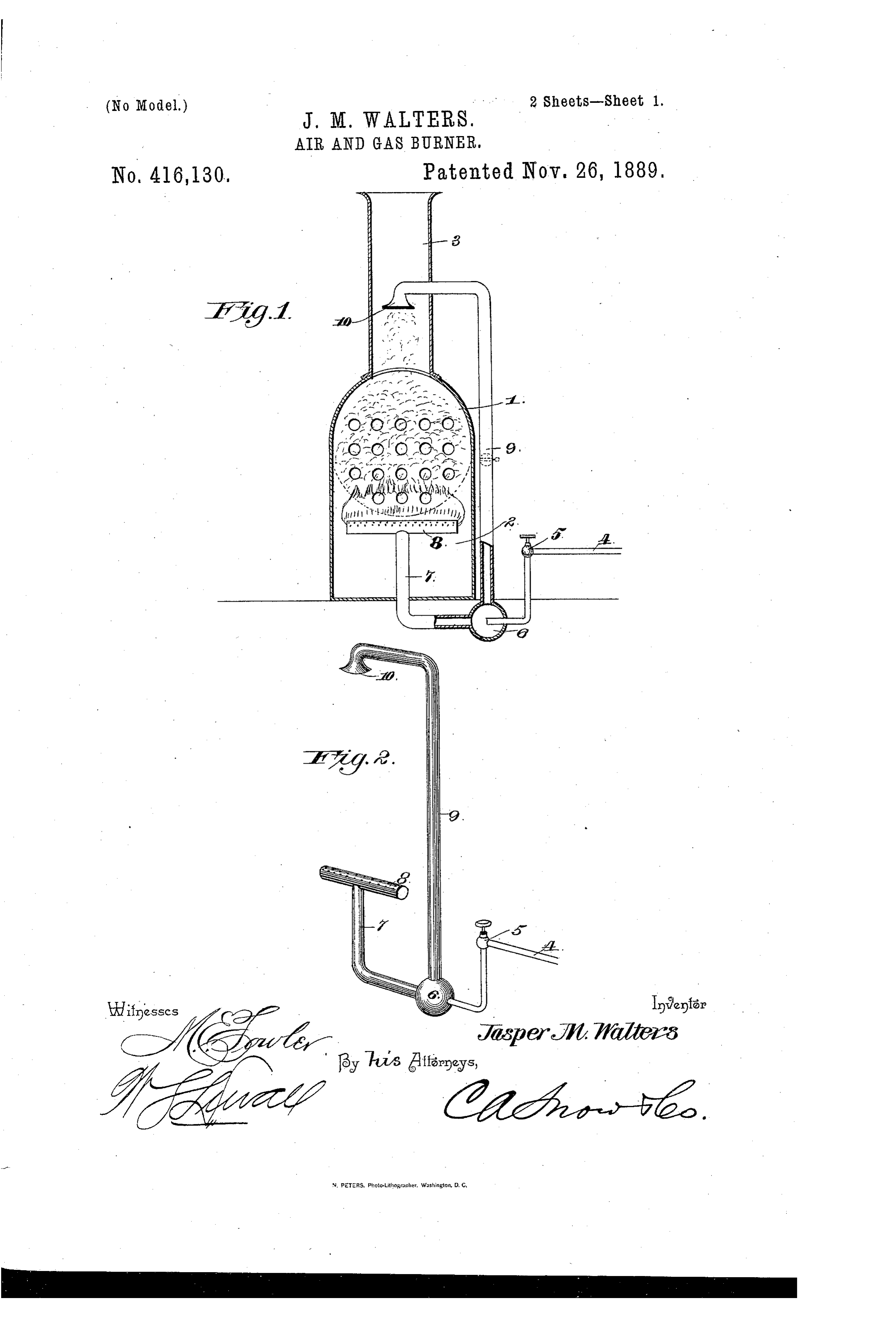
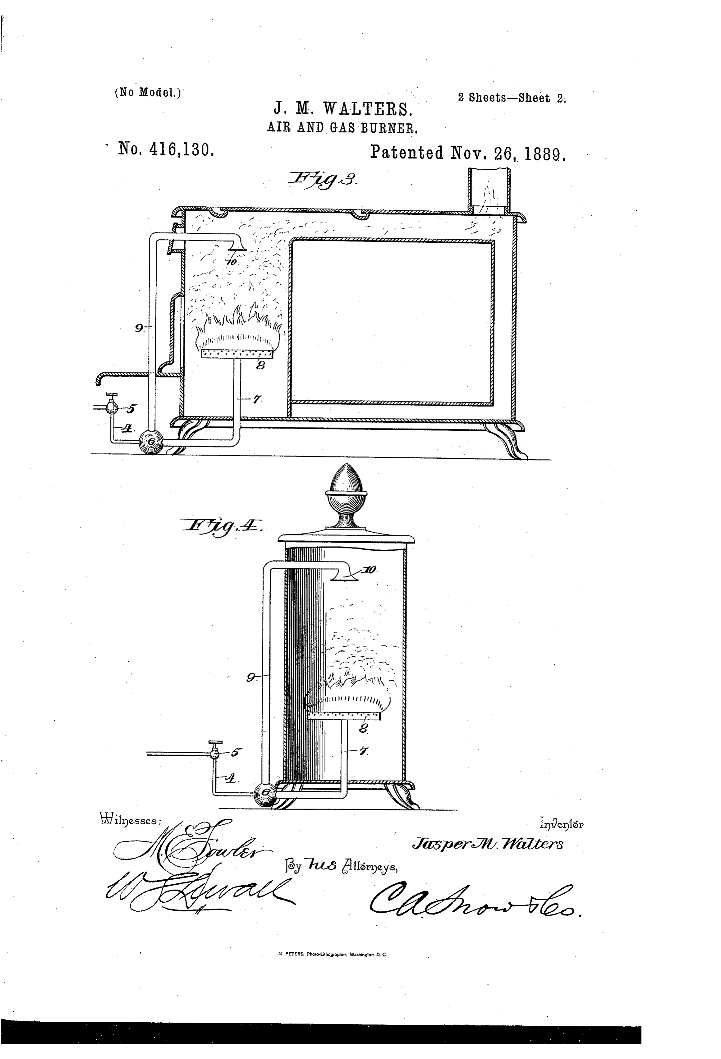
Referring to the drawings, Figure 1 is a transverse vertical section of an ordinary boiler provided with an air and gas burner constructed in accordance with my invention. Trig. 2 is a detail in perspective of the invention detached. Fig. 3 shows my invention applied to an ordinary cooking-stove, and Fig. 4 to a heating-stove.
Like numerals of reference indicate like parts in all the figures of the drawings.
Referring particularly to Fig. 1,1 represents an ordinary steam-boiler of the horizontal type, and below the same is arranged the usual fire-box 2, and above this boiler and communicating with the fire-box the smoke-
stack 3. From any suitable soure of supply there leads the gas-pipe 4, provided near the boiler with a suitable valve 5, and terminating, preferably below the floor, in an imperforate spherical chamber or mixer 6.
ing from.the chamber 6 and up through the bottom of the fire-box is the combined gas
and air pipe 7, the rear end of which com-
municates with the chamber 6,and at its upper end_thereis formed the usual transverse-
ly-disposed perforated. burner-pipe 8, which
lies directly under the boiler and in a posi-
tion to deliver the burning flame of gas and
air directly to the surface thereof.
9 represents the hot-air pipe, the open or. induction end of which is preferably flared or bell-shaped, as at 10, and the opposite or eduction end communicates with the chamber 6.
In Fig. 1,wherein [illustrate my invention as applied to a steam-boiler, I have, for the purpose of securing the best results, located the flared induction end of the pipe 9 directly above the fire-box 2 and within the smokestack, whereby the. heated air arising from the fire-box is induced by the draft to enter the pipe 9, and is conducted from thence into the chamber 6.
In practicing my invention the pipes 9and 7 are constructed considerably larger than the gas-pipe 4. The valve 5 being closed, it will be noticed that the receiver and the pipes 9 and 7 are filled with air. The valve being opened, the pressure of gas forces the airfrom the pipe 7, and the air from the pipe 9 is induced to descend into the receiver 6. The flame, being ignited, heats the air, and the same is carried to the pipe 9 and again tothe receiver, thus keeping up a continuous cireulation of hot air. The effect of such a mixing of hot air with the gas previous to its reaching the point of combustion is well known and will be readily appreciated, as I effect a saving in the consumption of the gas.
Referring to Figs. 3 and 4, it is apparent -
that the only modification necessary in practicing my invention in this class of stoves is to locate the induction end 10 of the pipe 9 at a suitable point, or where the greatest draft of hot air oceurs.
If desired, I may provide the hot-air pipe 9 with a valve, (shown by dotted lines in Fig. .
Page 4
1,) whereby the circulation of air does not take place until the air above the burner has become heated, when said valve is opened. Such a construction also prevents an upward rising of the gas through the pipe 9 when the valve 5 is first opened. This tendency, however, is overcome by the pipe 4 terminating near to the eduction end of the pipe 7.
By reason of forming the mixing-chamber imperforate the whistling, roaring noise so objectionable is avoided and the gas deodorized.
Having thus described my invention and its operation, what I claim is—
1. Ina burner of the class described, the combination, with a mixing-chamber, of a burnerpipe leading therefrom and terminating in.a burner, a gas-supply pipe terminating in said chamber, and a hot-air pipe communicating with said chamber and terminating in a line of draft with the burner, substantially as specified.
2. Ina burner of the class described, a mixing-chamber, a supply-pipe, and a gas and air pipe extending therefrom and terminating in a burner, in combination with a hot-air pipe communicating with the chamber and having its opposite end flared and arranged. above the burner, substantially as specified.
3.. Ina burner of the class described, a mixing-chamber, an air and gas pipe leading therefrom and terminating in a burner, a hot-air pipe terminating in the mixing-chamber and projecting upwardly and terminating at its opposite end in a flared receiver arranged above the. burner, and a gas-supply pipe provided with a valve and terminating
in the mixing-chamber and in line with the air and gas pipe, substantially as specified.
4. The combination, with a steam-boiler 1,
having the fire-box 2 and the smoke-stack 3, of the mixing-chamber 6, located near the boiler and having the enlarged gas and air pipe 7, terminating in the burner 8 , and the enlarged hot-air pipe 9, communicating with the. chamber and terminating at its opposite end in the flared mouth 10, located in the smoke-stack, and the gas-pipe 4, smaller than the pipes 7 and 9 and provided with the valve 5, and terminating in the mixing-chamber and opposite the pipe 7, substantially as specified.
- 5. In an air and gas ‘burner, the imperforate chamber 6, having a burner- pipe 7, terminating in a burner, the hot-air pipe 9, terminating in the flared mouth 10, and the gassupply pipe 4, terminating in the mixer, all combined as specified.
6. The combination, with a steam-boiler 1, of the mixing-chamber 6,: located near the boiler and having the gas ‘and air pipe 7, terminating in the burner 8, and the hot- air pipe 9, communicating with the chamber and terminating at its opposite end in the flared mouth 10, located in the smoke-stack, and the gas-supply pipe 4, leading to the mixingchamber, substantially as specified.
In testimony that I claim the foregoing as my own I have hereto affixed my signature in presence of two witnesses.
JASPER M. WALTERS.
Witnesses:
THOMAS C. DUNN,
W. W. SHULER,
Provenance
- Collection
- Cited prior art
- Original PDF
- patentimages.storage.googleapis.com →
- Pages
- 4
- Method
- pdftoppm 300dpi + tesseract 5 (eng)
- Source
- Google Patents bibliographic record
- Granted
- 1889-11-26
- Transcribed from
- patentimages.storage.googleapis.com →