patent · US4104883
Mass transport heat exchanger method and apparatus for use in ocean thermal energy exchange power plants
8 August 1978
Page 1 — bibliographic record
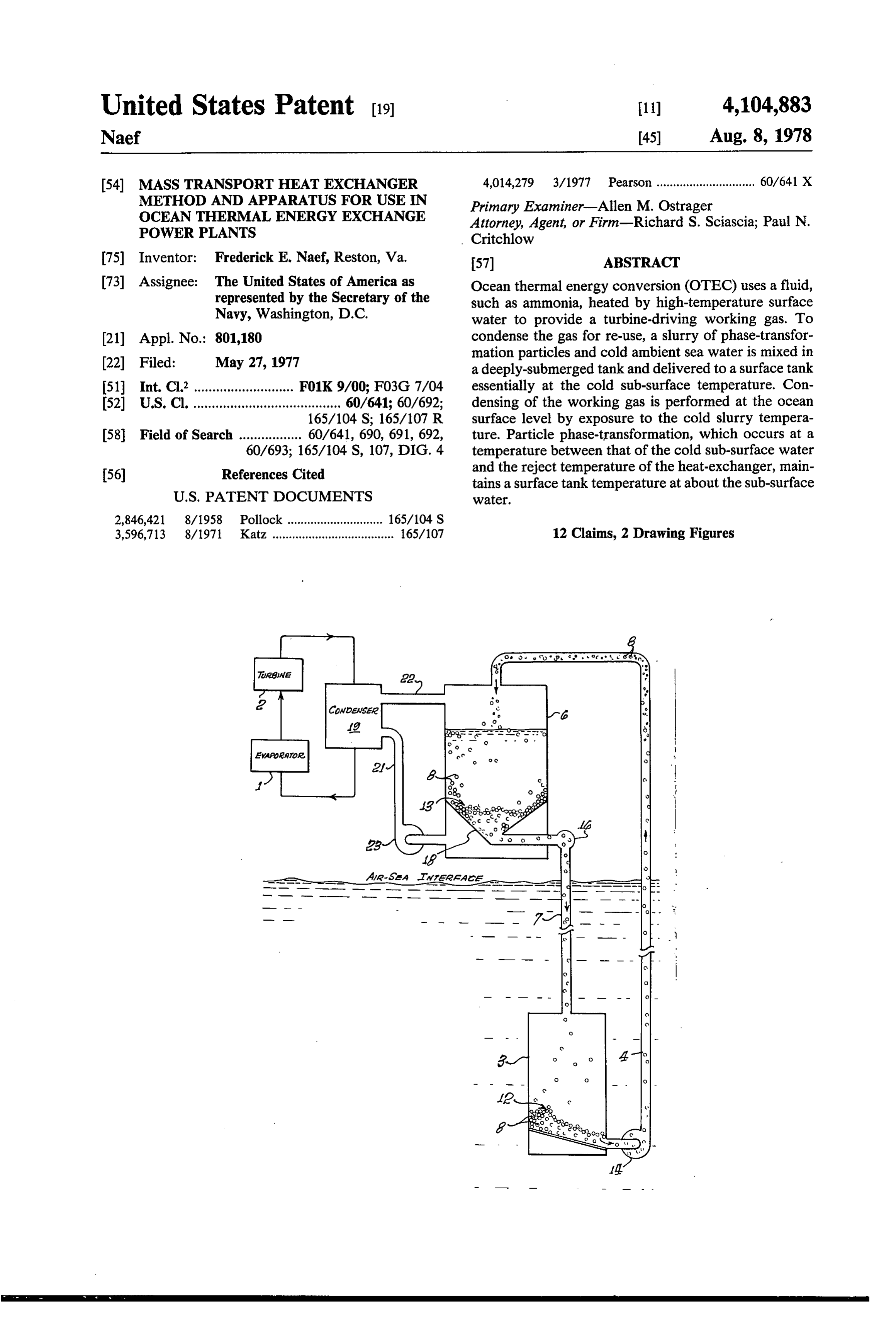
United States Patent (19) 11) 4,104,883 Naef 45) Aug. 8, 1978 (54) MASSTRANSPORT HEAT EXCHANGER 4,014,279 3/1977 Pearson .............................. 60/641 X METHOD AND APPARATUS FOR USE IN Primary Examiner-Allen M. Ostrager OCEAN THERMAL ENERGY EXCHANGE Attorney, Agent, or Firm-Richard S. Sciascia; Paul N. POWER PLANTS Critchlow
I75 Inventor: Frederick E. Naef, Reston, Va. 57) ABSTRACT (73) Assignee: The United States of America as Ocean thermal energy conversion (OTEC) uses a fluid, represented by the Secretary of the such as ammonia, heated by high-temperature surface Navy, Washington, D.C. water to provide a turbine-driving working gas. To 21) Appl. No.: 801,180 condense the gas for re-use, a slurry of phase-transfor 22 Filed: May 27, 1977 mation particles and cold ambient sea water is mixed in a deeply-submerged tank and delivered to a surface tank (51) Int. Cl’........................... F01K 9/00; F03G 7/04 essentially at the cold sub-surface temperature. Con (52) U.S. Cl. ........................................ 60/641; 60/692; densing of the working gas is performed at the ocean 165/104 S; 165/107 R surface level by exposure to the cold slurry tempera 58) Field of Search ................. 60/641, 690, 691, 692, ture. Particle phase-transformation, which occurs at a 60/693; 165/104 S, 107, DIG. 4 temperature between that of the cold sub-surface water (56) References Cited and the reject temperature of the heat-exchanger, main tains a surface tank temperature at about the sub-surface
2,846,421 8/1958 Pollock ............................. 165/104 S 3,596,713 8/1971. Katz ..................................... 165/107 12 Claims, 2 Drawing Figures
Page 2
Drawing sheet — no readable text.
Page 3
A further object is to increase the efficiency of these
MASSTRANSPORT HEAT EXCHANGER systems by applying material phase transformation phe METHOD AND APPARATUS FOR USE IN OCEAN nomena to the heat-exchange operations. THERMAL ENERGY EXCHANGE POWER Still another object is to provide a system which, in PLANTS effect, is self cleaning insofar as bio-fouling is involved. It is to be noted that the present invention has been Other objects will become more apparent in the ensu developed with the support of the National Science ing description.
Foundation. Generally, the objects are achieved by employing a BACKGROUND OF THE INVENTION slurry of particles which undergo a phase transforma 10 tion, such as a solid-liquid transformation, at a tempera
The present invention relates to heat-exchange sys ture between that of the cold, subsurface water and the tems and, in particular, to systems for condensing the condenser reject temperature. The slurry is formed by working gas of ocean thermal exchange power plants. mixing the particles with cold sea water at the depth of Although due to its almost unlimited availability and the cold water and by delivering the slurry to the ocean relative cleanliness, the use of ocean thermal energy as 15 surface where its coldness is used to condense the work a power source is unusually attractive, there are a num ing gas of the energy conversion systems. Release of ber of serious problems and difficulties which must be latent heat of fusion helps to maintain the cold water resolved if practical, cost-effective systems are to be wter temperature. Use of the slurry minimizes the widely used. In these systems which are known by the amounts of cold water pumped to the surface and it acronym OTEC, a working gas, such as the ammonia or 20 reduces size requirements, costs and parasitic pumping propane, initially is heated by surface water tempera losses.
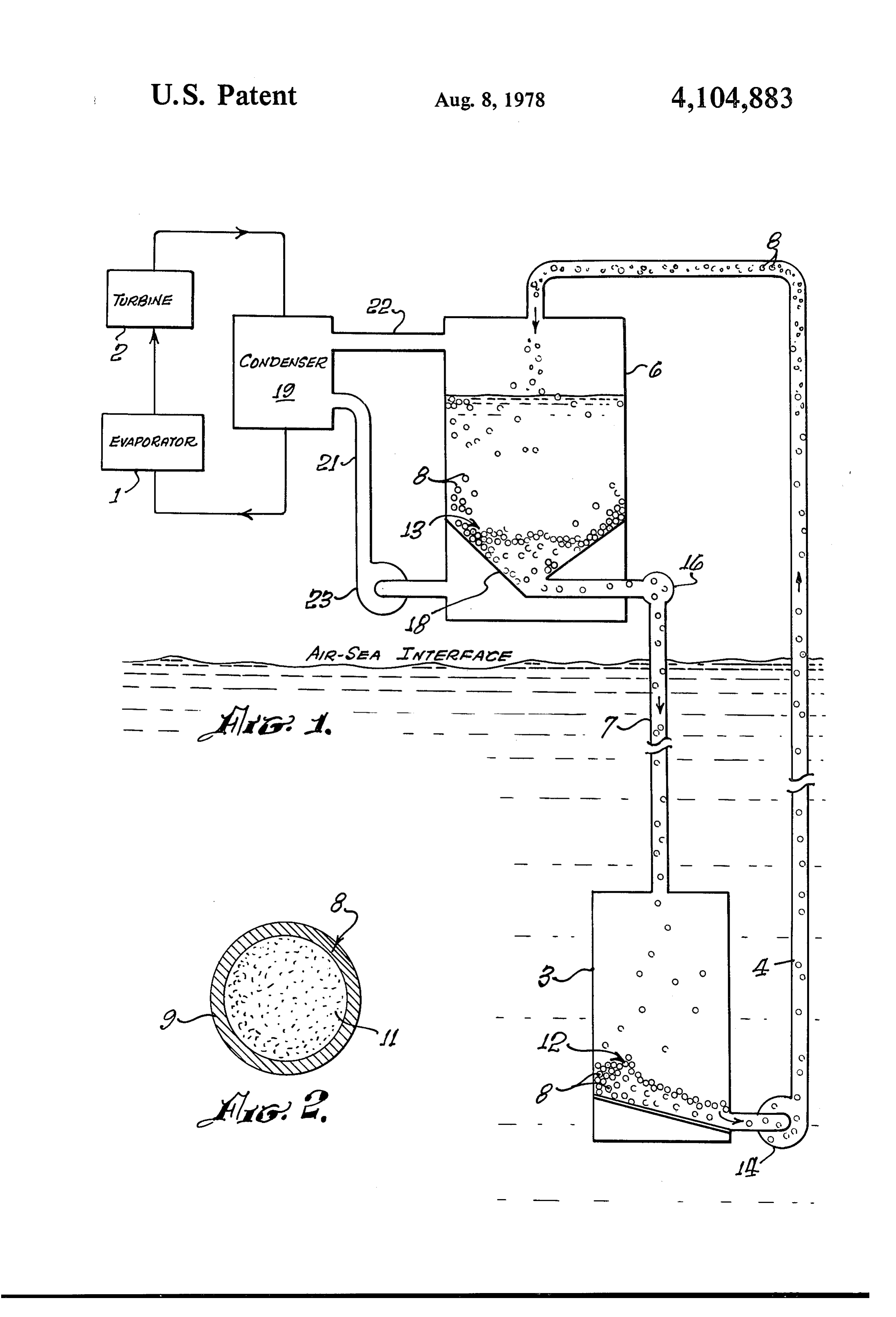
tures to form a gas for driving turbines that produce electrical power for transmission to shore stations. The BRIEF DESCRIPTION OF THE DRAWINGS gas then is condensed for return to the evaporator, the 25 The present invention is illustrated in the accompany condensing being achieved by using the cold tempera ing drawings of which:
ture of relatively deep ocean water. FIG. 1 is a schematic illustration of one form of the One of the more difficult problems involves the huge present system, and amounts of cold sea water which must be provided to FIG. 2 is an enlarged sectional view of one of the the condenser heat-exchanger and the fact that these phase-transformation particles.
amounts either must be pumped to the surface from 30 ocean depths or the heat-exchanger itself must be DETAILED DESCRIPTION OF THE placed deep in the ocean. The requirement for large INVENTION amounts of condensing sea water exists because of the OTEC systems are rather well known and have been small temperature differential and consequently low 35 described in numerous publications. They use a work thermal efficiency. The system requires extremely large ing gas, such as ammonia or propane, supplied in a heat transfer surfaces which necessitate heat exchangers liquid form to an evaporator identified in the present approximately the size of a seven story building. The drawing by numeral 1. The ammonia is heated by warm pump requirements, piping size, drag forces, etc. must 80 F surface water to convert it to a gas which drives be commensurably large. The alternate system in which a turbine 2. The generated turbine power is transmitted the large heat-exchanger is placed at the cold water to shore stations for consumer use.
depth presents other problems such as the need to move A problem with which the present invention is partic the working gas from the surface to the depth and to ularly concerned involves the need to condense the gas return the condensed fluid back to the evaporator at the effluent of the turbine back to liquid form for re-cycling surface. Another difficult problem is that the large heat 45 through the evaporator. Conventionally, the cold tem exchange structures must be firmly secured in the ocean perature needed to condense the working gas from the depth and this need, aside from the resulting expense of turbine is supplied by extending an extremely large pipe the structure, seriously complicates maintenance and to a depth of perhaps 2,000 feet to permit the cold water repairs. at that depth to be pumped to the condenser. Since as Operation of OTEC systems in the ocean water in 50 has been indicated, the condenser or heat-exchanger of volves a further complication in that the tubes of the conventional systems is about the size of a seven story heat-exchanger are susceptible to bio-fouling which building, it is apparent that huge amounts of water must results from bio-activity promoted by the nutrients pres be pumped from the depth to the surface and that the ent in the cold, sub-surface water. Bio-fouling of heat piping as well as the pumping must have extremely exchanger tubes materially reduces or degrades their 55 large capacities. The evaporator, the turbine and the effectiveness so that steps must be taken either to avoid condenser usually are carried on a floating barge or the or to remove the bio-fouling during operation. In fact, like directly above the cold water pipe which extends to this fouling is one of the largest problems facing the the cold water depth.
industry. Also, it is one that is endemic in that the nutri The present invention is characterized by the fact ent gradient exists at the ocean depths where the essen that, instead of pumping copious supplies of cold water tial cold water is found. to the surface, the system employs a slurry formed of It is therefore an object of the present invention to sea water and a large supply of pellets or particles provide an ocean thermal exchange system in which the which, preferably, have about a neutral buoyancy to size and the cost of the pumping, piping and the heat minimize pumping requirements. As shown, it employs exchange structure are effectively reduced. 65 a sub-surface tank 3 connected by a delivery pipe 4 to a Another object is to reduce the amounts of cold sea surface tank 6. A return line 7 communicates the lower water transported to the surface, thus reducing size, portion of tank 6 to the upper portion of sub-surface costs and power requirements. tank 3.
Page 4
Contained within both tanks 3 and 6 are beds of parti ticles in their liquid form are lighter, they can be re cles 8 which, for present purposes, can be visualized as turned through conduit 7 under a hydrostatic head. relatively large pellets or capsules of perhaps the size of Further, materials may be found which have a so-called a golf ball. Preferably, each of these particles 8, is a reverse phase-transformation characteristics. In other spherical capsule (FIG. 2) having an outer protective 5 words, particles in their solid form are less dense and shell 9 encapsulating a material 11 which is a phase tend to float, while, in their liquid form, they become transformation material capable of undergoing a phase more dense and tend to sink. In such an event, the parti change at a particular temperature. For example, mate cles tend to float upwardly in conduit 4 and down rial 11 may be the common heat exchange material NaK wardly in conduit 8. In any event, particles 8 should which is soft, silvery, solid or liquid sodium-potassium 10 have a near neutral buoyancy which substantially mini alloy which undergoes a solid-to-liquid phase transfor mizes pumping requirements.
mation in a 40-60 Frange. Shell 9 can be formed of a An important consideration in the present system is plastic, ceramic, glass, or, if extra protection is needed, one of assuring that sub-surface bed 12 has a sufficiently of steel or other relatively strong metals. long residence time in tank 3 to permit the particles to The selection of the encapsulating coating material 15 solidify at the temperature of the cold, sub-surface wa will depend somewhat upon the phase-transformation ter. To achieve this purpose, tank 3 not only should be material which is used. However, it should have a high large but, in particular, the flow rate in delivery line 4 temperature conductivity to permit the phase-transfor and return line 7 should be quite slow. Also, solidifica mation material to respond promptly to ambient tem tion time can be materially reduced by employing a peratures. Some trade-off may be needed between the 20 pump to induce cold water circulation through the tank obvious desire to gain conductivity by reducing the 3. If increased residence time is desired, several sub-sur shell thickness and the need to have a strong shell wall face tanks 3 can be employed. In this arrangement one to resist wear. Another factor to be considered in the or more are used as stand-by tanks while another is material selection is the desirability of minimizing bio operatively coupled to the surface tank. Thus, the resi fouling tendencies. 25 dence time can be increased relative to that achievable Phase transformation materials are quite well known with a single sub-surface tank.
and have been used for a variety of heat-exchange pur The physical nature of the particles being delivered poses such, for example, as a control for the heat of from sub-surface tank 3 to the surface tank is, as already chemical reactions. As stated, NaK is functionally ac indicated, a slurry formed of both water and the golf ceptable although it also is expected that a variety of 30 ball-sized pellets or particles. The slurry is formed by other less reactive materials, such as waxes, etc., can be circulating cold ambient sea water through the particle used. As is known, phase-transformation with its ac bed in tank 3 and the particles, along with some of the companying heat release occurs not only in solid-liquid water is delivered through conduit 4 to the surface tank. transformations but also in other types of transforma Preferably, the tank 3 employs an inclined baffle mem tions such as solid-solid or crystalline. As will become 35 ber 17 or the like near its bottom portion to direct the apparent, the particular type of transformation pres slurry into the inlet end of delivery pipe 4. At the outlet ently used is of little concern provided it is capable of end of this pipe, the slurry is delivered into a space releasing its latent heat at the operating temperature of provided above packed bed 13. The return flow of the the system. In this regard, it can be noted that the prin particles and some of the sea water is facilitated by cipal function of the capsules or pellets used in the FIG. 40 employing another inclined baffle 18 in tank 6. This 1 apparatus is to absorb the cold water energy during baffle is a screen-like member which permits sea water their residence time in tank 3 and to release this energy delivered to the upper portion of tank 6 to drop into the in the form of latent heat of fusion when delivered into particle-free lower portion of the tank for use as a con tank 6. densing medium.
Other aspects of the present invention best can be 45 A heat exchanger 19 condenses the working gas or understood by considering the operation of the sche ammonia delivered to it from evaporator 1 and turbine matically illustrated system. As a starting point, it can 2. As will be appreciated, the gas passes through the be considered that sub-surface tank 3 contains a supply condenser in thin-walled pipes which are cooled by sea or bed 12 of ball-sized particles 8 and that surface tank water. The sea water is supplied through a closed-loop 6 also contains a similar bed 13. The particles of sub-sur 50 circuit formed of an inlet pipe or conduit 21 coupled to face bed 12 are to be delivered to surface tank 6 and, for the particle-free portion of surface tank 6 and an outlet this purpose, a pump 14 is coupled into delivery line 4. pipe 22 which leads into the upper, empty portion of Also, particles present in surface bed 13 are returned to tank 6. Conduit 22 returns condenser-reject sea water to sub-surface bed 12 and, as needed, another pump 16 tank 6 at particular elevated temperature determined, of may be coupled into return line 8. However, under 55 course, by the amount of energy extracted from the sea certain circumstances, only one or the other of pumps water for condensing purposes. A pump 23 forces the 14 and 16 may be needed and, assuming appropriate sea water in conduit 21 through the condenser and back into surface tank 6. Most suitably, the pump is con particles can be found, there may be situations in which trolled little or no pump power is required. For example, it is to provide a relatively fast flow rate in the known that the specific gravity of encapsulated solid closed loop of the sea water provided by pipes 21 and state NaK particles can be about 9 so that they tend to 22.
float upwardly in delivery pipe or conduit 4. Of course, Packed bed 13 of surface tank 6, in effect, acts as a if relatively heavy casings or shells are used, some pump constant temperature heat sink for the condenser at a power may be needed although it will be considerably temperature that is essentially equal to that of the sub less than that otherwise required for the copious water 65 surface water in which tank 3 is disposed. More specifi deliveries. Power for returning encapsulated liquid cally, the operation of the system contemplates delivery NaK pellets from surface bed 13 also is minimized and of the slurry into tank 6 at essentially the sub-surface conceivably eliminated. For example, although the par temperature which may be in the range of 40-45° F and,
Page 5
for this purpose, pipe 4, as well as the other pipes of the volumes of water are piped at a relatively slow rate system, are formed or insulated to maintain their influ through the condensers and the condensers must have a ent temperature. Also, surface tank 6 and condenser 19 capacity to handle this large volume. In the present are insulated structures which, in actual practice, may system, the flow rate through the condenser is relatively be heavy concrete structures having sufficiently thick fast and the lag mean temperature difference is small, walls to maintain their interior temperatures. Even so, permitting the same cooling effect to be accomplished there will be some warming of both the particles and the with a smaller heat exchanger. Further, as is apparent, water of the slurry delivered to tank 6. Also, the resi relatively little sea water is delivered through pipe 4 dence time in the tank 6 permits warming. However, into the surface tank due to the fact that the flow rate efficient operation of the system requires that the slurry 10 through this delivery line is quite slow and that the delivered to tank 6 be essentially the temperature of the slurry being delivered is, in large part, formed of the ambient sub-surface water so that the heat of fusion is particles themselves.
not released at least until the particles come to rest in A further important consideration involves the bio bed 13. It is the release of this heat of fusion within fouling problem caused by the use of the nutrient-rich packed bed 13 which is largely responsible for maintain 15 cold sea water which promotes bio-fouling. In the pres ing the bed at essentially the temperature of the ambient ent system, bio-fouling is minimized first by the fact that sub-surface water. In other words, it permits the bed to the nutrients in the sub-surface are formed in large part act as the constant temperature heat sink at the sub-sur on the particles themselves and that a substantial face temperature. amount is returned by the particles to the sub-surface To achieve this purpose, it is preferred to use phase 20 depth. Further, it is possible to clean and inspect the transformation at a temperature between that of the particles as they are delivered to tank 6 by removing cold sub-surface water and that of the condenser reject increments of the incoming particles for scrubbing and water delivered to tank 6 through conduit 22. Specifi replacement. The high flow rate of the sea water cally, if the sub-surface temperature is 40' and the con through the condenser has less nutrients since, as stated, denser reject temperature is about 60, the particles 25 a considerable amount of the nutrients are carried back undergo a phase transformation within this range and, to the sub-surface by the particles. preferably, well above the 40' temperature so as to Although the system illustrated in the drawing has assure their solid state on arrival at the tank. The warm definite advantages, it also is contemplated that addi ing effects on the particles of the condenser reject water tional significant advantages can be obtained by utiliz as well as other warming effects are compensated by 30 ing surface tank 6 itself as a heat-exchanger. The con their state change with its energy release. Consequently, denser 19 could be further reduced in size and the need the condenser water passing through screen 18 into the for condenser 19 no longer would exist. Also, the lower portion of tank 6 is essentially at the temperature closed-loop circuit for circulating water through the of the sub-surface water. The flow rates both of deliv separate condenser could be eliminated. Use of surface ery line 4 and return line 7, as well as the flow rate 35 tank 6 as a heat-exchanger contemplates delivery of the through the condenser are controllable for this purpose. working gas directly into the surface tank. In such an The control achieves an optimum flow of the cold operation, a slurry, such as has been described, is deliv water through tank 6 and an optimum residence time of ered in the same manner to the tank which includes a the particles within this tank. Preferably, this residence separator, such as a rotary separator, to separate the sea time assures the return of the particles to sub-surface 40 water from the particles and dry the particles. The tank 3 before particles become super-heated. One rea working gas or ammonia then is separated and returned son for avoiding super-heating is to reduce the resi to the evaporator. The particles themselves are returned dence time needed in sub-surface tank 3 to absorb the in the manner already considered to the sub-surface ambient temperature. tank. One of the advantages in such an arrangement is Some of the advantages inherent in the illustrated 45 the further reduction and possible elimination of the arrangement include, first, the fact that the pumping heat exchanger. Another is that the system, in effect, is requirements for delivering the slurry to tank 6 and self-cleaning insofar as bio-fouling is involved. The returning it to the sub-surface tank are reduced. The self-cleaning is achieved by the fact that the spherical reduction is achieved by utilizing particles or pellets particles constantly are rubbing together and the nutri which have a near neutral buoyancy so that relatively 50 ents carried by the particles rub off and can be elimi little pump power is required to lift them to the surface nated. Such a system also may utilize the fluidized bed or return them to the sub-surface. As already indicated, technology of the petroleum to provide a heat ex it is conceivable that particles 8 can beformed of appro changer in the form of tank 6 in which the usual tube priate materials permitting them to rise during delivery type exchanger is replaced by the heat exchange pellets. and fall during return. For example, it is known that the 55 It further is to be recognized that, although the prin petroleum industry uses a fluidized technology to move ciples of the present invention generally contemplate catalyst beads from, for example, a reactor to the regen the condensation of the ammonia gas, they also can be erator. Utilizing this technology, the specific gravity or advantageously employed in the evaporation phase to weight of the particles can be adjusted for maximum initially provide the ammonia gas for the turbines. Thus, power reductions. In this regard, however, it is assumed liquid-phase particles can be delivered in a warm water that pumping power will be required either for delivery slurry to heat the liquid ammonia and produce the gas. or return of the slurry. In this regard, it is considered In fact, the liquid particles can also be the NaK ex preferable to provide particles having a specific gravity change material with the desired phase change tempera permitting them to float during delivery. Pump 16 then ture controlling the varying proportions of the sodium is used to assure their return and control the flow rate. 65 and potassium. Use in the evaporation phase would be A further advantage in the illustrated system is that particularly advantageous in an evaporation system that heat-exchanger 19 can be of a considerably reduced separates the warm slurry water from the particles and size. Thus, in conventional OTEC proposals, very large then uses the particles themselves to evaporate incom
Page 6
ing liquid ammonia. In fact, applying the separation recirculating it back into the surface tank at a con concept to both condensation and evaporation serves to trolled flow rate, and eliminate the use of the conventional large tanks used means for exposing said working gas to the tempera for both condensing and evaporating. ture of said surface tank bed for condensing said gas,
Obviously many modifications and variations of the said exposure elevating the temperature of water present invention are possible in the light of the above returned to said surface tank by said second recir teachings. It is therefore to be understood that within culating circuit and said particles being formed to the scope of the appended claims the invention may be undergo a phase transformation between the tem practiced otherwise than as specifically described. 10 perature of said cold sub-surface water and said It is to be noted that the present invention has been elevated temperature for maintaining said surface developed with the support of the National Science tank bed essentially at the temperature of said cold Foundation. sub-surface water.
I claim: 5. The apparatus of claim 4 wherein said particle 1. A method of condensing the working gas of an 15 phase transformation is a solid-liquid transformation. ocean thermal energy conversion system comprising: 6. The apparatus of claim 5 wherein said particles mixing in a sub-surface tank disposed at an ocean each are formed of a capsule including:
depth a supply of temperature-sensitive phase a material characterized by its ability to undergo a transformation particles with cold ambient sea 20 solid-liquid phase transformation in said surface water for forming a slurry having a temperature tank bed, and essentially equal to that of the ambient water, a capsule casing formed of a temperature-conductive delivering said cold slurry upwardly from said tank material, depth into a surface-disposed tank, said capsules having a specific gravity close to that of returning said particles from said surface tank to said 25 7. sea The water for providing a near neutral buoyancy.
apparatus of claim 5 wherein said mass trans sub-surface tank, port conduit circuit means includes pump means for exposing at said surface level said working gas to the movably delivering said slurry to said surface tank at a temperature of the surface tank slurry, and controlled and relatively-slow flow rate determined in withdrawing the sea water from said surface tank and accordance with said circuit return flow rate for main recirculating it as an influent back into said surface 30 taining said beds, said particles being returned to said tank, sub-surface tank by the hydrostatic head provided by said temperature-sensitive particles being of a type said surface tank bed.
capable of undergoing a phase transformation at a 8. The apparatus of claim 6 wherein said capsule temperature between that of said sub-surface ambi specific gravity is less than that of said cold sea water ent sea water and said surface tank influent. 35 whereby said particles in said slurry floatably rise for 2. The method of claim 1 wherein said particles have delivery to said surface tank.
a near neutral buoyancy. 9. The apparatus of claim 8 wherein said mass trans 3. The method of claim 1 wherein said particles un port conduit circuit includes a pump means for return dergo a solid to liquid phase transformation at a temper ing said particles to said sub-surface tank, pump means ature of from about 40' to 60' F. being controlled in accordance with the flow rate of 4. Mass transport heat exchanging apparatus for con said delivery for maintaining said particle beds. densing the working gas of an ocean thermal energy exchanger 10. The apparatus of claim 4 wherein said heat conversion system comprising: further includes: a mass of bead-like particles formed to undergo a 45 a condenser tank receivably coupled to said working latent heat-releasing phase transformation at a par gas, said condenser tank being coupled into said ticular temperature, second recirculating circuit for exposing said working gas to the cold water temperature of the a sub-surface tank disposed in a cold water environ water in said second circuit. ment at a fixed ocean depth, said tank containing a 11. The apparatus of claim 10 wherein said particle fluid particle and water slurry bed at essentially the 50 bed partially fills said surface tank and both said deliv temperature of said cold water environment, ered slurry and said recirculated condensing water are a heat-exchanger including a second tank disposed delivered into a space provided above the surface tank near the ocean surface and also containing a bed of bed.
said particles, 12. The apparatus of claim 11 wherein said surface a mass transport conduit circuit means for controlla 55 tank further includes:
bly delivering said slurry from said subsurface tank a baffle member for directing said particles into the to said surface tank and for returning said delivered particle return portion of said mass transport con particles back to said sub-surface tank whereby duit circuit and for separating said slurry water in said circuit beds are maintained, said surface tank bed from said particles for deliv a second conduit circuit means for withdrawing 60 ery into said recirculating
and
condensing conduit.
slurry water delivered to said surface tank and
Provenance
- Collection
- Cited prior art
- Original PDF
- patentimages.storage.googleapis.com →
- Filed
- 1977-05-27
- Pages
- 6
- Method
- pdftotext (the PDF's own text layer) + pdftoppm 300dpi page scans
- Source
- Google Patents bibliographic record
- Granted
- 1978-08-08
- Inventors
- Frederick E. Naef; US Department of Navy
- Transcribed from
- patentimages.storage.googleapis.com →