patent · US3682239
Electrokinetic heat pipe
8 August 1972
Page 1 — bibliographic record
United States Patent 15) 3,682,239
(54) ELECTROKINETIC HEAT PIPE 57 ABSTRACT (72) Inventor: Momtaz M. Abu-Romia, 124 Amity A heat pipe for transporting a large quantity of heat St., Brooklyn, N.Y. 11201. within a small temperature difference provided with a 22) Filed: Feb. 25, 1971 tube, a wick, and a fluid that can transfer heat. The 21 Appl. No.: 118,756 tube includes an evaporator section at one end and a condenser section at the opposite end thereof. The wick is disposed uniformly against the side walls of the 52 U.S. Cl........................... 1651, 165/105, 310/2, tube and provides a capillary action to transfer the 31015, 417/48 fluid from the condenser section to the evaporator 51 Int. Cl............ . . . . . . . . . . . . . . . . . . . . . . . . . . . . . . . F28d 15/00 section. Heat at the evaporator section causes the 58 Field of Search............ 165/107, 105, 1; 417/48; fluid to evaporate, wherein the vapor is then trans 310/2, 5, 6 mitted to the condenser section where the vapor con denses, thus giving up its latent heat, and is again 56 References Cited transmitted to the evaporator section by the wick to define a continuous flow within the heat pipe. Elec
UNITED STATES PATENTS trodes are disposed within the tube, one electrode 3,417,267 12/1968 being disposed adjacent to the evaporator section, and Marks......................... ...310/6 the other electrode being disposed adjacent to the 3,441,752 4/1969 Grover et al................... 310/4 condenser section. When a potential difference is ap OTHER PUBLICATIONS plied to the electrode, an electro-osmotic flow pump ing is effected within the pipe, thereby, increasing the
Solion (Distributed by O.T.S. Dept. of Commerce), maximum heat capability of the heat pipe or overcom O.D. 561, U5-1958 ing any vapor lock present in the wick. Without the applied potential difference, the heat pipe functions as
Primary Examiner-Albert W. Davis, Jr. either an electrokinetic power generator or as a poten Attorney-Friedman & Goodman tial generator.
23 Claims, 3 Drawing Figures
ADA BATC
CONDENSER
COO. NG
Page 2
Drawing sheet — no readable text.
Page 3
ELECTROKNETCHEATPPE BRIEF DESCRIPTION OF THE DRAWINGS BACKGROUND OF THE INVENTION Having in mind the above and other objects that will Heat pipes are well known in the art. These heat be evident from an understanding of this disclosure, the pipes have a fraction of the weight, and several hun invention comprises the devices, combinations and ar dred times the heat transfer capability of solid copper, rangements of parts as illustrated in the present preferred embodiments of the invention which is silver or aluminum. Heat pipes can replace many con hereinafter duction heat-transfer systems, thereby improving per skilled in thesetart forth in such detail as to enable those readily to understand the function, formance of nearly any energy-conversion system. It is operation, construction and advantages of it, when of considerable interest at the present time to find the read in conjunction with the accompanying drawings in maximum heat transferred by these heat pipes, and which:
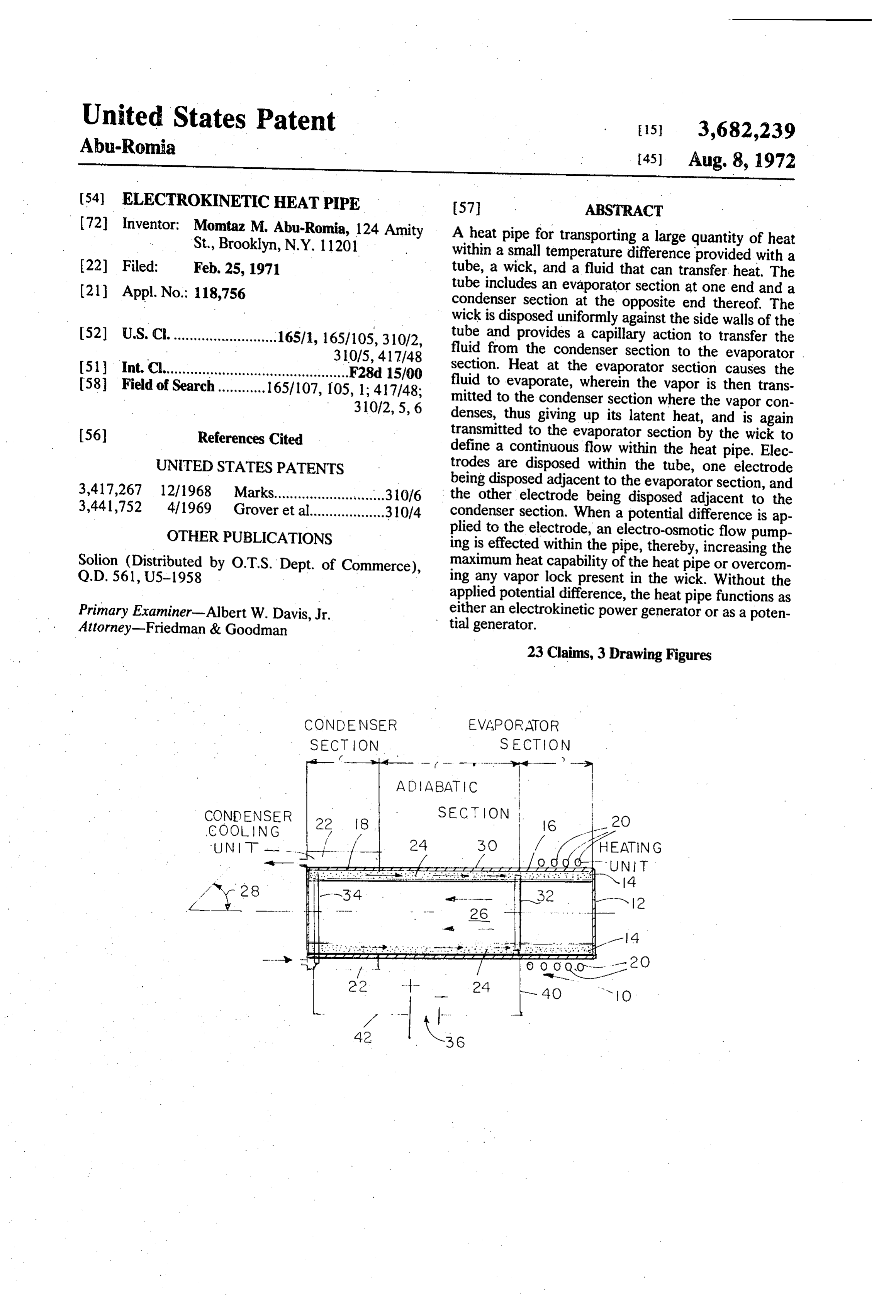
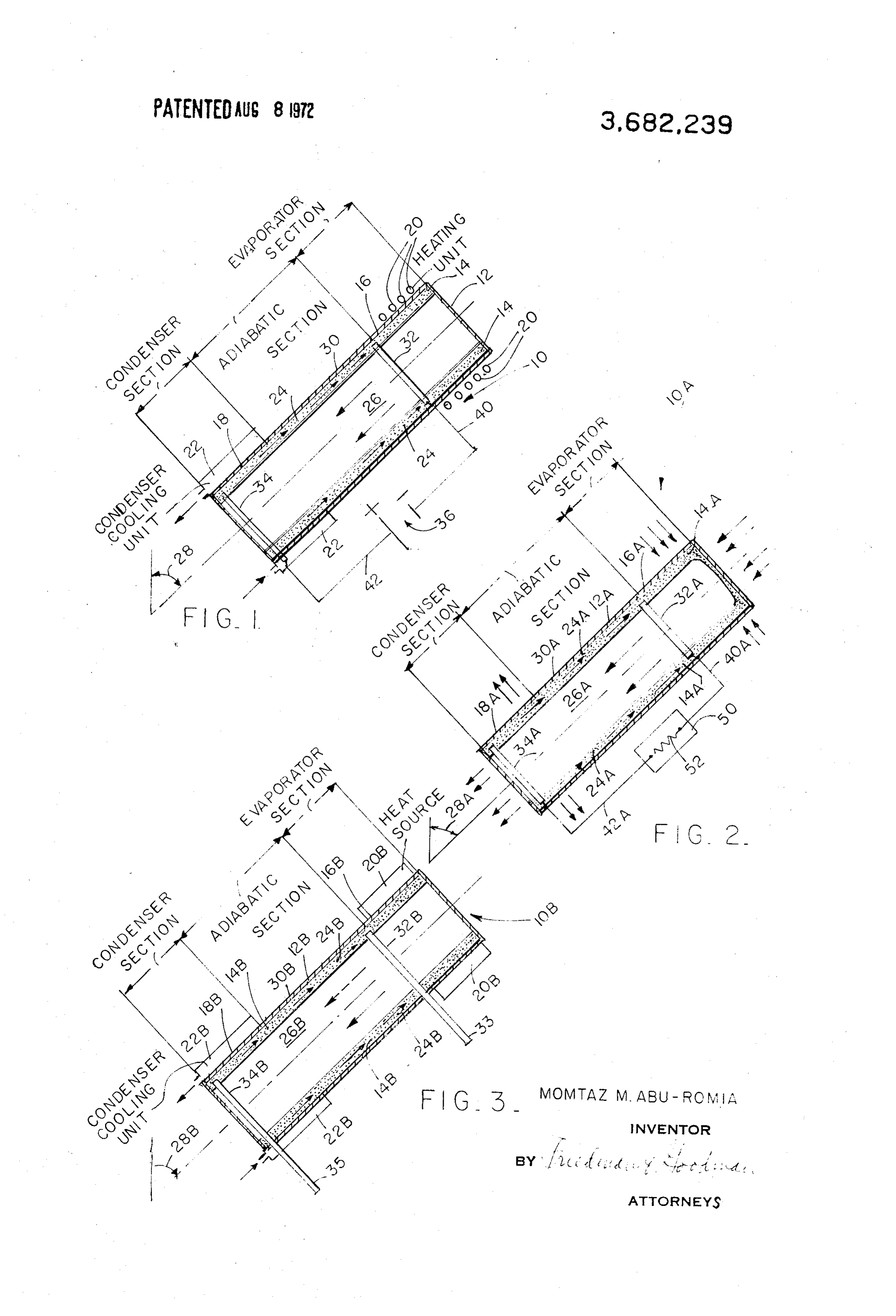
what modifications could be incorporated in the pipes FIG. 1 is a schematic representation of a heat pipe to increase their heat capacity for given evaporator, according to the present invention featuring electro condenser and wick parameters. It is recognized that 15 osmotic flow pumping;
the rate of heat transfer by a heat pipe is limited by the FIG. 2 is a schematic representation of a heat pipe capacity of its capillary pump and/or by the presence of according to the present invention, functioning as an vapor lock in the wick at the evaporator section. The electrokinetic power generator; and present invention considers the employment of elec 20 FIG. 3 is a schematic representation of a heat pipe according to the present invention functioning as a trodes in heat pipes for increasing its heat capacity, potential overcoming the vapor lock in the wick, and for using generator.
the heat pipe as a generator. DESCRIPTION OF THE PREFERRED
EMBODIMENT
Referring to the drawings, FIG. 1 illustrates a heat
This invention relates to the art of transferring heat, pipe and more particularly to a heat pipe for transferring cludes 10 of the present invention. The heat pipe 10 in a tube 12 and a wick 14. The tube 12 defines a heat from one point to another. The heat pipe com closed outer shell preferably provided with a circular prises a tube, a wick within the tube, fluid that can 30 cross-section, however, the tube may assume any transfer heat and electrodes disposed within the tube. desired geometric shape. The wick 14, which is a com The electrodes permit the heat pipe to function as a mercially available porous capillary wick, is held by generator in one form of the invention. In anotherform conventional means uniformly against the inside walls of the invention, a potential difference is applied to the of the tube 12 extending from one end portion 16 of the electrodes so that the heat pipe provides an electro 35 tube 12 to the opposite end portion 18 thereof. The end osmotic flow pumping therein to increase the max portion 6 defines the evaporator section and the end imum heat capability of the heat pipe and to overcome portion 18 defines the condenser section, as will be set any vapor lock present in the wick. forth in more detail hereinafter below. Accordingly, an object of the present invention is to 40 A heating unit 20 is disposed on the evaporator sec provide a heat pipe for transporting a large quantity of tion 16. The heating unit 20 is of the conventional type, heat which overcomes the disadvantages of the prior such as a heating coil containing heated gases, fluids, art. solids, or thermal radiation at the evaporator section 16 Another object of this invention is to provide a heat so that the heat may be transferred therefrom. A con pipe, wherein an increased heat pipe capability is ob 45 ventional condenser cooling unit 22 is disposed on the tained for given evaporator, condenser and wick condenser section 18 to remove the heat from the heat perameters. pipe 10. Conventional cooling fluids, such as water, A further object of this invention is to provide a heat may be used in the cooling unit 22 as indicated by the arrows in FIG.
pipe which overcomes any vapor lock present in the 50 therefrom. to assist in the heat removal wick.
A fluid that can transfer at a phenomenal rate is
And a further object of this invention is to provide a disposed heat pipe which includes electro-osmotic flow pumping within the heat pipe 10. Many different types therein. of liquids such as: benzene, gasoline and water solu A still further object of this invention is to provide a 55 tions that can be used as working fluids. It has been found favorable results are achieved with dilute water heat pipe provided with electrode means for starting up solutions, such as the pipe to reduce the transient period required in the mospheric carbondistilled water in equilibrium with at dioxide. The fluid is in the form of a prior art.
And yet a further object of this invention is to pro of liquid 24 when flowing in the wick 14, and in the form vide a heat pipe that functions as an electrokinetic 60 assetfortha vapor 26 when flowing centrally within the tube 12 power generator. hereinafter below. The function of the structure thus far described will
And yet a still further object of this invention is to now be set forth. The heat pipe 10, as shown in FIG. 1, provide tor.
aheat pipe that functions as a potential genera is disposed at any angle 28 between 0 and 180 from the vertical position. In operation, the liquid 24, due to
An added object of this invention is to provide a 65 the capillary action of the wick 14 will climb up device that can transfer heat at a phenomenal rate through the porous capillary wick 14 to the upper por which is simple, inexpensive and very reliable. tion of the tube 12 where it will evaporate under the
Page 4
higher temperatures to which this protion 16 of the heat pipe 10. Considerably higher efficiencies are at tube 12 and the capillary wick 14 are subjected; the tainable with the use of ultrafine tubular capillaries. heat being added by the material contained within the The wick material can be glass, ilmenite, quartz, clay, heating unit 20. This evaporated liquid will collect in foam, paper or any other suitable substance. the form of the vapor 26 in the evaporator section 16, Preferably, the wickmaterial of the present invention is and by progressive accumulation therein, will be forced chosen to be glass beads based on the knowledge of the down through an adiabatic intermediate section 30 of surface properties of glass in contact with a water solu the tube 12 to the bottom portion 18 of the tube 12. tion. If a flexible heat pipe is desired, a flexible wick The vapor 26 will condense within the condenser sec 10 material such as fiberglass may be used. Preferably, the tion 18 to again form the liquid 24, wherein the cooling tube 12 is constructed of conventional dielectric unit will remove the heat therefrom. The above process materials, which are well known in the art. is again repeated so that a continuous flow is main The heat pipe 10 which is sealed or enclosed as tained. Thus, by this principle, the heat pipe 10 trans shown in FIG. 1, has a quickstarting up time because of mits heat downwardly through evaporation and con 5 the effect of the electro-osmotic pumping. Therefore, densation, and raises liquid upwardly without the ex once the heat pipe 10 has been started up and a con penditure of any work in raising the liquid. tinuous flow is established, the applied potential from Accordingly, to increase the maximum heat capabili the source 36 may be disconnected from the heat pipe ty of the heat pipe 10 and to overcome any vapor lock 10, wherein the heat pipe 10 will continue to operate as present in the wick 14, a pair of electrodes 32 and 34 20 set forth above, however, at a lower heat capacity. are disposed within the heat pipe 10. The electrode 32 is disposed between the evaporator section 16 and the Therefore, as shown above, the electro-osmotic pump ing of the heat pipe 10 can be continuously used or aidabatic section 30, with the electrode 34 being used only for starting up the heat pipe to reduce the disposed at a lower portion of the condenser section transient period thereof.
18. A potential difference from a conventional source 25 36 is applied to the electrodes 32, 34 through lines 40, ofFIG. the 2 illustrates a second embodiment of a heat pipe present invention wherein similar parts are 42 respectively. denoted by similar reference numerals. Electrokinetic flow phenomena are dependent upon the presence of a naturally occurring potential, or a 12A andconstruction,
In this a wick 14A a heat pipe 10A includes a tube having similar construction to charge accumulation at the interface of the fluid and 30 tube 12 and wick 14 mentioned above. The tube 12A the capillary walls. The surface potential causes aredis includes an end portion 16A defining an evaporator tribution of the charged ions present in the fluid, so that section, an intermediate portion 30A defining an the movement of the fluid is thereby accompanied by a adiabatic section, and an opposite end portion 18A movement of charge. When the fluid is moved through 35 defining a condenser section. A fluid similar to the a capillary element, an axial streaming potential above-mentioned fluid of heat pipe 10, is disposed gradient is generated which is directly proportional to within the heat pipe 10A so that a liquid 24A flows in the pressure gradient and to the electrokinetic mobili the wick 14A and a vapor 26A flows centrally within ty. Conversely, when an axial potential gradient is ap the tube 12A in the space or passage provided therefor. plied to the capillary element, flow is generated which is directly proportional to the potential gradient. The 40 The28A heat pipe 10A is disposed at a predetermined angle between 0 and 180, as stated above.
former phenomena is denoted as a streaming current generator and is associated with electrokinetic power disposed within athepair
Accordingly, of electrodes 32A and 34A are generation as will be discussed hereinafter below. The is disposed between the pipe heat 10A. The electrode 32A latter phenomena is called electro-osmotic flow pump 45 the adiabatic section 30A, with thesection
ing and is utilized in connection with the heat pipe as being disposed at a lower portion of the condenser 34A electrode sec shown in FIG. 1.
The electrodes 32 and 34 provide an axial potential tion 18A. Anyone of a plurality of electrically operated gradient within the heat pipe 10, being applied to the objects 50 provided with a resistance 52 may be as capillary wick 14. Both electrodes 32 and 34 are 50 sociated connected with the heat pipe 10A. The resistance 52 is in series through lines 40A and 42A to the porous, with the electrode 34 being positively charged and the electrode 32 being negatively charged. With electrodes 32A, 34A, respectively, in order to operate the presence at a net charge density within the wick, the object 50, assetforth hereinafter below. the axial potential gradient produced by the electrodes The heat pipe 10A defines an electrokinetic power 32, 34 creates an electro-osmotic force which causes 55 generator. As stated above, a naturally occurring an increase in the flow of the liquid 24 towards the potential is present within the heat pipe 10A, with a evaporator section 16. The increased flow between the charge accumulation at the interface of the liquid 24A electrodes 32,34 is directly proportional to the applied and the capillary walls of the wick 14A, causing a redis potential from the source 36. tribution of the charged ions present in the liquid 24A. 60 When the liquid 24A flows through the capillary wick
With the electrodes providing an electro-osmotic flow pumping, the angle 28 at which the heat pipe 10 is 14A, there is also a movement of charge therethrough disposed can be zero whereby there still will be pro so that an axial streaming potential gradient is vided a continuous flow within the heat pipe 10, or any generated. Since the net charge density is often posi angle between 0 and 180 degrees, as stated above. 65 tive, fluid motion causes the porous electrodes 32A to Decreasing the capillary channel width of the wick 14 be positively charged and the porous electrode 34A to causes a greater charge density of the liquid 24 thereby be negatively charged, so that electrical power is increasing the flow and improving the efficiency of the generated to the resistance 52 of the object50.
Page 5
Rather than employing heating units, the evaporator gradient causes the porous electrode 32B to be posi section 16A is preferably heated by the sun. Preferably, tively charged, and the porous electrode 34B to be the wick 4A is disposed uniformly against the side negatively charged, so that a potential is effected walls and end wall of the evaporator section 16A to in between the outwardly extending portions 33 and 35 of crease the efficiency of the heat pipe 10A. Addi the electrodes.
tionally, rather than employing a condenser cooling Rather than employing heat coils, the evaporator unit, the condenser section 18A is air cooled with the section 16B is heated by any conventional heat source condenser section 18A being shaded from the sun by 20B. Additionally, rather than employing a condenser conventional means (not shown).
In operation, the liquid 24A, due to the capillary ac 10 cooling means may beshown cooling unit 22B as used.
in FIG. 3, any conventional tion of the wick 14A, will climb up through the porous capillary wick 4A to the upper portion 16A of the tionIn of operation, the liquid 24B, due to the capillary ac tube 12A where it will evaporate under the higher tem capillarythewick wick 14B, will climb up through the porous 14B to the upper portion 16B at the tube peratures to which this portion 16A of the tube 12A 2B, where it will evaporate under the higher tempera and the capillary wick 14A are subjected; the heat 15 tures to which this portion 16B of the tube 12B and the being obtained from the sun. This evaporated liquid capillary wick 14B are subjected; the heat being ob will collectin the form of the vapor 26A in the evapora tained from tor section 16A, and by progressive accumulation will collect inthetheheat source 20B. This evapoated liquid therein, will be forced down through the passage in the 20 tor section 16B, andofbytheprogressive form vapor 26B in the evapora accumulation adiabatic intermediate section 30A of the tube 12A to the bottom portion 18A of the tube 12A. therein, will be forced down through the passage in the The vapor 26A will condense within the condenser the adiabatic intermediate section 30B of the tube 12B to section 18A to again form the liquid 24A, with the air bottom portion 18B of the tube 12B. disposed around the outer surface of the condenser 25 The vapor 26B will condense within the condenser section 18A removing the heat therefrom. The above section 18B to again form the liquid 24B, where the process is again repeated so that a continuous flow is condenser cooling unit 22B disposed around the outer maintained, during which time the electrodes 32A and surface of the condenser section 18B will remove the 34A are charged to supply electrical power to the ob heat therefrom. The above process is again repeated so ject 50. It is obviously understood, that the heat pipe 30 that a continuous flow is maintained, during which time 10A will function equally as well with heating and cool the electrodes 32B and 34B are charged to effect a ing units as described above. potential between portions 33 and 35 of the electrodes. FIG. 3 illustrates a third embodiment of a heat pipe It is noted that adiabatic sections 30, 30A and 30B of the present invention, wherein similar parts are 35 transfer the heat from the evaporator sections to the denoted by similar reference numerals. condenser sections without any loss or gain of heat, In this construction, a heat pipe 10B includes a tube thus simplifying its design and operation, and providing 12B and a wick 14B having similar construction to the an unlimited number of practical applications thereof. tube 12 and the wick 4 mentioned above. The tube Numerous alterations of the structures herein dis i2B includes an end portion 16B defining an evapora 40 closed will suggest themselves to those skilled in the tor section, an intermediate portion 30B defining an art. As for example, in the absence of the adiabatic sec adiabatic section, and an opposite end portion 8B tion of the heat pipe, both electrodes are to be em defining a condenser section. A fluid similar to the bedded within the condenser section. It is to be un above-mentioned fluid of heat pipe 10, is disposed derstood that the present disclosure relates to a within the heat pipe 10B so that a liquid 24B flows in 45 preferred embodiment of the invention which is for the the wick 14B and a vapor 26B flows centrally within purpose of illustration only, and not to be construed as the tube 12B in the space or passage provided therefor. a limitation of the invention.
The heat pipe 10B is disposed at a predetermined angle What is claimed is:
28B between 0 and 180, as stated above. 1. Aheat transfer device comprising a body member, Accordingly, a pair of electrodes 32B and 34B are 50 said body member including a first portion for receiv disposed within the heat pipe 10B. Electrode 32B is ing heat from a heat source and a second portion for disposed between the evaporator section 16B and the transferring heat away from said body member, capilla adiabatic section 30B, with the electrode 34B being ry means extending between said first and second por disposed at a lower portion of the condenser section tions, said body member being provided with a passage 18B. The electrode 32B and 34B have portions 33 and 55 communicating with said first and second portions, a 35, respectively, extending outwardly from the outer liquid associated with said capillary means, spaced surface of the tube 2B, the function of which will be apart electrode means disposed within said body set forth herein below. member for cooperation with said capillary means, said The heat pipe 10B defines a potential generator. As electrode means being associated with a potential stated above, a naturally occurring potential is present gradient functioning within said body member, and within the heat pipe 10B, with a charge accumulation non-conductive means for isolating said spaced elec at the interface of the liquid 24B and the capillary walls of the wick 4B, causing a redistribution of the charged trode member.
means from one another within said body ions present in the liquid 24B flows through the capilla 65 2. A heat transfer device according to claim 1, ry wick 14B, there is also a movement of charge therethrough so that an axial streaming potential wherein said capillary means includes a porous capilla gradient is generated. This axial streaming potential body member. uniformly against inside walls of said ry wick disposed
Page 6
3. A heat transfer device according to claim 1, potential generator.
wherein said body member includes a sealed tube, said 16. A method of transferring heat from a first point first portion defining an evaporator section and said at a higher temperature to a second point at a lower second portion defining a condenser section. temperature employing a device containing a liquid, 4. A heat transfer device according to claim 3, said method comprising evaporating the liquid at the wherein an adiabatic section of said tube is disposed first point to form a vapor, condensing the vapor at the between said evaporator and condenser sections. second point, returning by capillary action the con 5. A heat transfer device according to claim 3, denser liquid from the second point to the first point, and applying a potential gradient to the returning con wherein a heat source is disposed adjacent to said 10 densed liquid.
evaporator section.
6. A heat transfer device according to claim 5, 17. A method according to claim 16, wherein a first wherein said heat source includes a heating unit electrode second is disposed adjacent to said first point, a electrode is disposed adjacent to said second disposed around said evaporator section.
7. a heat transfer device according to claim 3, 15 point, and a potential difference is applied to said first wherein cooling means are disposed adjacent to said and second potential to provide said potential gradient to produce electro-osmotic flow pumping.
condenser section.
8. A heat transfer device according to claim 7, source 18. A method according to claim 17, wherein a heat wherein said cooling means include a condenser cool higher temperature, is disposed at said first point to provide said ing unit disposed around said condenser section. and cooling means are disposed at 9. A heat transfer device according to claim 1, 20 sails: EssigEEEiao wherein said body members are disposed at a predeter transfer heat from a first point at a higher temperature mined angle between 0 and 180 from vertical posi to a second point at a lower temperature for producing tion. a generator, said method comprising evaporating the 10. A heat transfer device according to claim 1, 25 liquid at the first point to form a vapor, condensing the wherein said electrode means includes a first electrode vapor at the second point, returning by capillary action associated with and disposed adjacent to said first por the condensed liquid from the second point to the first tion, and a second electrode associated with and point, and producing a potential gradient associated disposed adjacent to said second portion. with the movement of the returning condensed liquid. 11. A heat transfer device according to claim 10, 30 20. A method according to claim 19, wherein a first wherein a potential difference is applied to said first electrode is disposed adjacent to said first point, a and second electrodes to provide said potential second electrode is disposed adjacent to said second gradient to produce electro-osmotic flow pumping. point, said potential gradient providing a potential dif 12. A heat transfer device according to claim 11, ference between said first and second electrodes to wherein said body member is disposed at 0 with 35 produce said generator.
reference to vertical position. 21. A method according to claim 20, wherein a re 13. A heat transfer device according to claim 10, sistance is disposed in series with said first and second wherein said potential gradient produces a potential electrodes to produce an electrokinetic power genera difference between said first and second electrodes to tor.
provide a generator. 40 22. A method according to claim 20, wherein said 14. A heat transfer device according to claim 13, first and second electrodes are extended outwardly wherein a resistance is disposed inseries with said first from said device to produce a potential generator. and second electrodes to effect an electrokinetic power sourceAismethod 23. according to claim 20, wherein a heat disposed at said first point to provide said generator. higher temperature, and cooling means are disposed at 15. A heat transfer device according to claim 13, 45 said second point to provide said lower temperature. wherein portions of said first and second electrodes ex sk xk is tend outwardly from said body member to effect a
Provenance
- Collection
- Cited prior art
- Original PDF
- patentimages.storage.googleapis.com →
- Filed
- 1971-02-25
- Pages
- 6
- Method
- pdftotext (the PDF's own text layer) + pdftoppm 300dpi page scans
- Source
- Google Patents bibliographic record
- Granted
- 1972-08-08
- Inventors
- Momtaz M Abu-Romia; MOMTAZ M ABU ROMIA
- Transcribed from
- patentimages.storage.googleapis.com →