patent · US3980907
Method and apparatus for generating electricity magneto hydrodynamically
14 September 1976
Page 1 — bibliographic record
United States Patent (19) 11, 3,980,907 Nakamura (45) Sept. 14, 1976
54) METHOD AND APPARATUS FOR 3,161,789 12/1964 Nagamatsu et al................... 310/11 GENERATING ELECTRICITY MAGNETO 3,444,401 5/1969 Gilli.................................... 31 014 X 3,477,878 11/1969 Hughes et al....................... 30/4 X
HYDRODYNAMICALLY
(75) Inventor: Takashi Nakamura, Mitaka, Japan OTHER PUBLICATIONS 73) Assignee: Asahi Kasei Kogyo Kabushiki Geomagnetism, Chapman and Bartels, Oxford Univer Kaisha, Osaka, Japan sity Press, 1940, p. 445.
22 Filed: Jan. 13, 1975 Primary Examiner-Donovan F. Duggan 21 Appl. No.: 540,331 Attorney, Agent, or Firm-Cooper, Dunham, Clark, Griffin & Moran (30) Foreign Application Priority Data
Jan. 16, 1974 Japan.................................. 49-707 57 ABSTRACT
Closed cycle energy conversion system in which a (52) U.S. C. ................................... 310/11; 310/4 R magnetohydrodynamic generator operates on high 51 ) int. Cl'............................................ H02N 4/02 temperature and high pressure water obtained by (58) Field of Search............................. 310/4, 10, 11 combustion of hydrogen in oxygen which is obtained by thermal decomposition of water to produce 56) References Cited electricity.
UNITED STATES PATENTS 16 Claims, 4 Drawing Figures 1509, 103 9/1924 Elliott, Jr.............................. 310/11
Page 2
Drawing sheet — no readable text.
Page 3
Drawing sheet — no readable text.
Page 4
METHOD AND APPARATUS FOR GENERATING FeO + CO - 3FeO + CO,
ELECTRICTY MAGNETO 2CO - 2CO - O
HYDRODYNAMICALLY A large number of additional reactions are illustrated 5 and discussed by Chao in Ind. Eng. Chem., Prod. Res.
BACKGROUND OF THE INVENTION Devel. 13, 94 (1974).
It is recognized that nuclear heat could be converted The thermal decomposition of water whether by into electricity using a high temperature gas reactor thermochemical means or by heat energy alone is well (HTCR) - magnetohydrodynamic generator (MHD) known and need not be discussed in detail. It is suffi - steam cycle with an overall efficiency higher than 10 cient to say that for many of the procedures large 50%, provided the gas temperature from the reactor amounts of thermal energy are required, and that for reaches about 1600°C. The outlet gas temperature efficient use of an MHD generator high temperatures from presently available HTGRs is not sufficiently high are required.
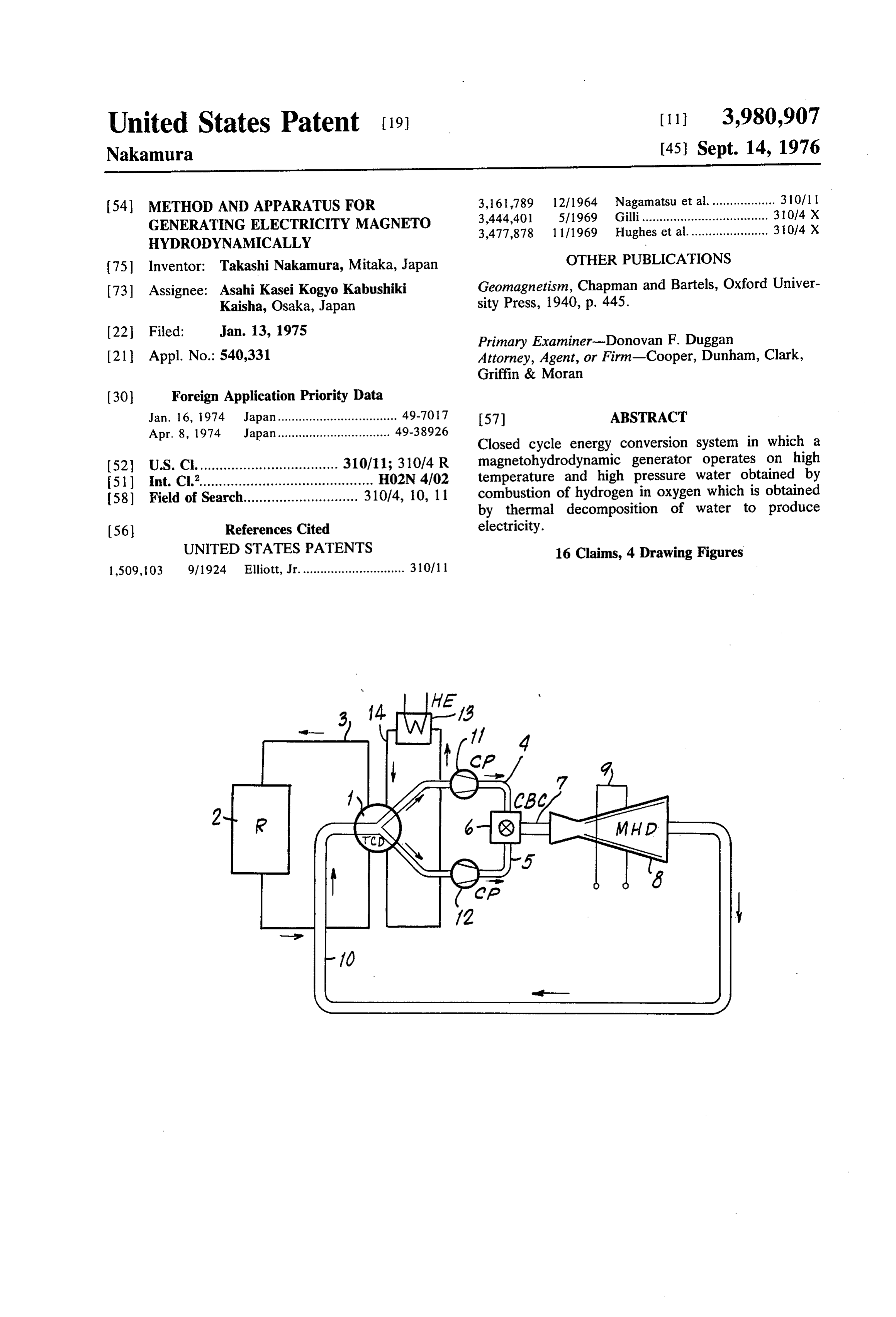
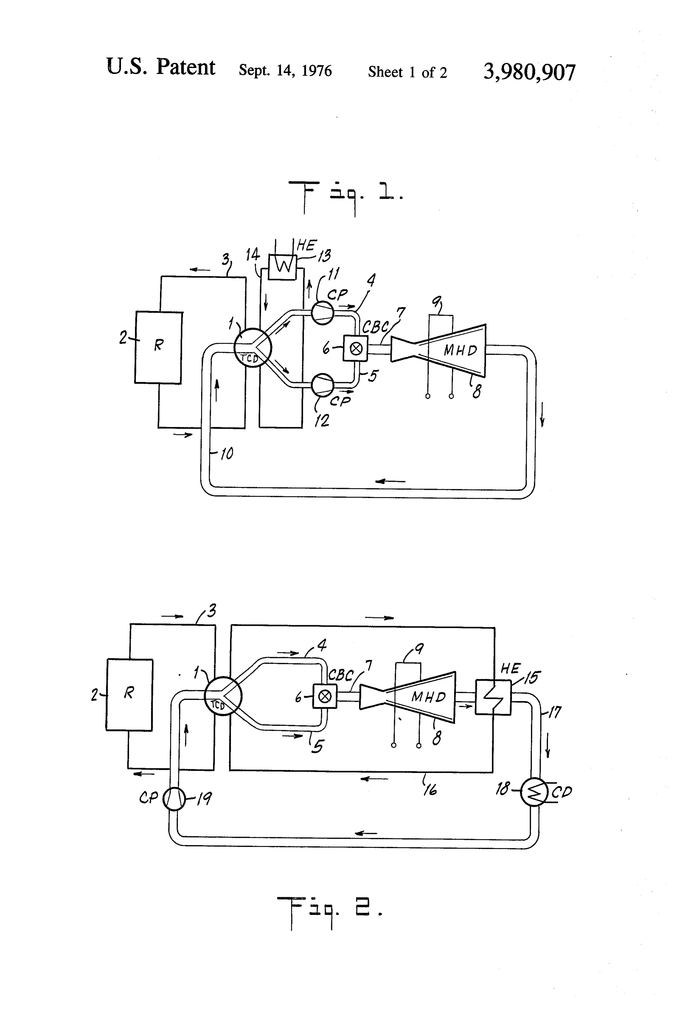
to reach this efficiency, and is not likely to reach this 15 One source of thermal energy to activate the decom temperature for the next several years. There remains, poser is illustrated in the figures as a thermonuclear therefore, a qualitative gap between the maximum reactor 2 which may be a high temperature or a low outlet temperature of existing and expected HTGRs temperature reactor with a coolant such as helium, and the minimum temperature necessary for efficient carbon dioxide, liquid sodium or other conventional operation of the HTGR-MHD-steam cycle. medium circulating in pipe 3. The process and apparatus of this invention makes 20 Hydrogen and oxygen from the decomposer are cir possible the efficient utilization HTGR for the produc culated in pipes 4 and 5 to combustion chamber 6 tion of energy in a closed cycle utilizing MHD. The where the hydrogen is burned in the oxygen to produce invention, however, is not limited to HTGR as the pri water high temperature, high pressure water. Typically the mary heat source. as it exits the combustion chamber will be at a 25 pressure of from about 25 to 30 atmospheres and a
THE INVENTION temperature of about 3000K to 3500K.
This invention relates to a novel closed cycle energy The high temperature, high pressure water which conversion system in which water is thermally decom exits the combustion chamber passes through pipe 7 to posed to hydrogen and oxygen which are then recom 30 MHD generator 8 where a portion of its enthalpy or bined to form high temperature high pressure water. heat energy is converted to electricity in a known man The water is passed through an MHD generator and a nerFIG. and picked up by leads 9. 1 shows an embodiment of the invention in portion of its enthalpy or heat energy is converted to electricity. A second portion of its heat energy is uti which the terminal energy of the effluent stream from lized to aid in the thermal conversion of the water to 35 the MHD generator is returned to the decomposer 1 hydrogen and oxygen. with high temperature, low pressure steam as the car The invention will be more readily understood from rier through pipe 10. The apparatus of FIG. 1 provides the following description taken together with the ap both heat energy and water for the decomposer 1. The pended drawings in which: heat energy supplements the heat energy from the pri FIGS. 1, 2,3 and 4 represent various embodiments of 40 tionmary heat source so as to aid in effecting the produc the invention. of hydrogen and oxygen. In FIG. 1 compressors 11 In the description of the invention, reference will be and 12 are used to increase the pressure of the gaseous made, for convenience, to a closed circuit for the circu streams before they enter the combustion chamber. lation of water. It will be apparent as the description FIG. 1 shows a heat exchanger 13 with coolant circu lating through pipe 14 to function as a heat sink for the progresses that this terminology is not strictly accurate 45 decomposer since in one phase of the cycle hydrogen and oxygen, 1.
the elements of water, are passing, and that in some which heat values inantheembodiment
FIG. 2 illustrates effluent of the invention in water stream from the phases the water is in liquid form while in others it is in MHD generator are extracted in the heat exchanger 15 the form of steam. It is not believed that the selected terminology will cause any confusion. by a coolant such as helium circulating in pipe 16. 50 There heat values are returned to the decomposer 1 to
The various embodiments of the invention illustrated in the figures represent alternate methods of returning supplement the heat energy of coolant 3. The effluent heat values from the MHD generator to the thermal through from heat exchanger 15 is conducted in pipe 17 decomposing means, as well as various methods of liquid condenser 18 where it is condensed to form utilizing the energy produced in the system. water and then to pump 19 and finally back to In accordance with the invention, water is thermally theFIG.3 decomposer 1.
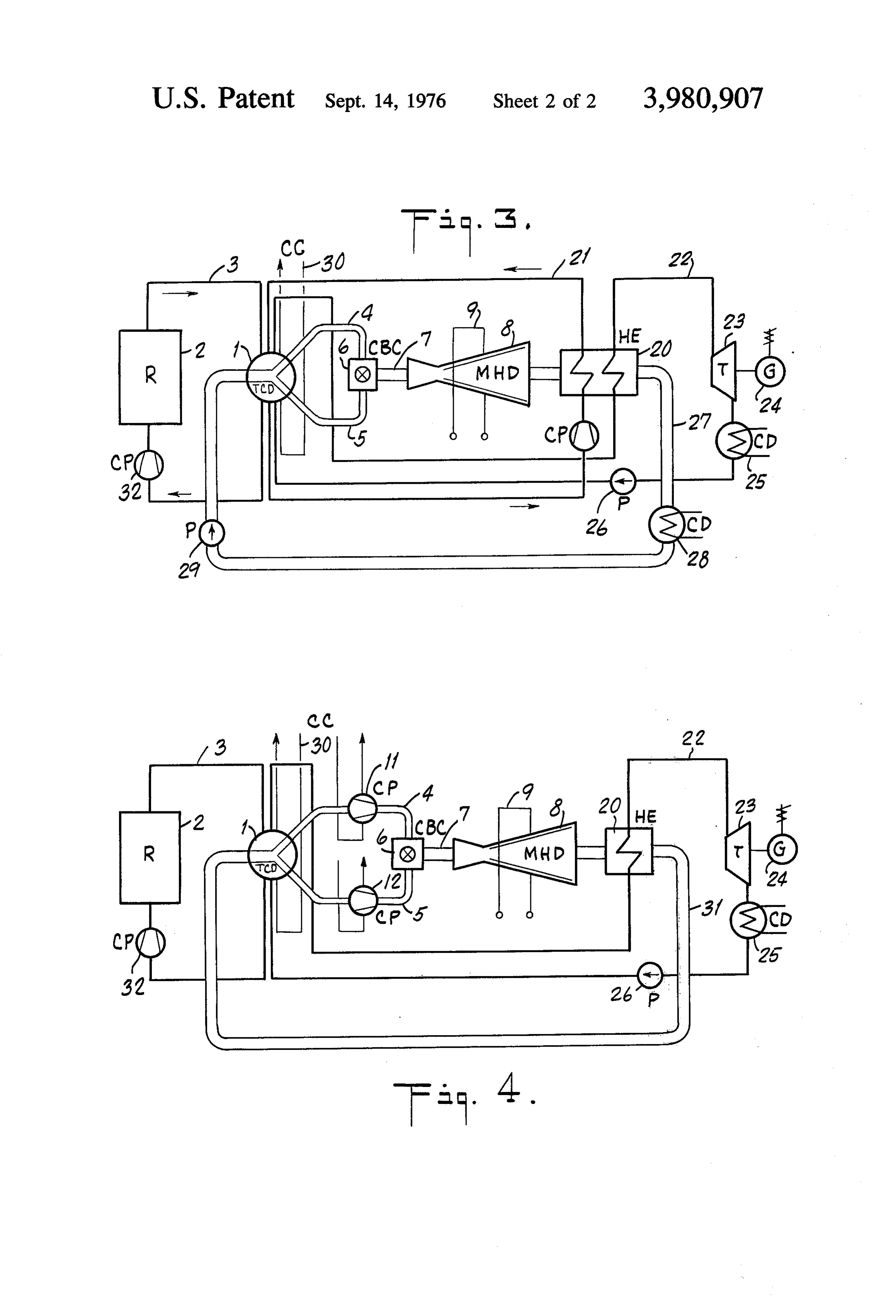
decomposed in thermal decomposition means 1 to which theshows an improved version of the invention in heat exchanger 20 is cooled by two streams produce hydrogen and oxygen. The water may be de so composed by thermal energy alone or, more conve thethat two separate portions of the heat values from effluent stream from the MHD generator are ex niently, by thermochemical decomposition involving a 60 tracted. The first coolant is helium or similar coolant series of reactions, the sum total of which is the conver circulating in, pipe 21 at a pressure of about 1 atmo sion of water to hydrogen and oxygen. sphere and a temperature of about 1700 K to supple One such series of reactions involved the use of ce sium, and is indicated as follows: ment the primary heat source. The second coolant is 2HO + 2Cs -> 2CsoH -- H, coolant steam circulating in pipe 22. The coolant steam 65 extracts a second portion of heat energy from the efflu
2CsO - CsC - 312O, ent stream to become superheated to a temperature of
Another is represented by the sequence: about 850K operating at a pressure of approximately Fe -- HO - H -- Fe0 250 atmospheres. The steam actuates a turbine 23 to
Page 5
produce mechanical energy which may be utilized, for possible to use low temperature nuclear heat as the example, to run an electrical generator 24. The steam primary heat source.
after passage through the turbine, is normally at a pres The sequence of conversion of water to hydrogen sure of about 0.05 atmospheres and a temperature of 5 and oxygen and their reconversion to water in the com about 310'K. It is condensed to water in condenser 25 bustion chamber can be initiated at start-up by provid which in turn is pumped by pump 26 to the decomposer ing hydrogen and oxygen from an auxiliary source. 1 where it is again heated to form steam by recovering What is claimed is:
the rejected heat from the decomposer. 1. A closed cycle process for magnetohydrodynamic The effluent stream from the heat exchanger 20 cir power generation which comprises the steps of: culates in pipe 27 back to the decomposer 1. In its 10 1. thermally decomposing water to generate hydro passage it is condensed to water at a temperature of gen and oxygen utilizing a primary heat source, about 300K and a pressure of 0.05 atmospheres in 2. recombining said hydrogen and oxygen in a com condenser 28. Pump 29 is utilized to increase the pres bustion chamber to form high temperature, high sure of the circulating water to approximately 30 atmo 15 3. pressure utilizing water, a first portion of the thermal energy in the spheres before it returns to the decomposer. FIG. 3 high temperature, high pressure water to produce shows a circulating water in circuit 30 operating as a electrical energy by forcing the water through a heat sink for the decomposer, the temperature of the magnetohydrodynamic generator thereby to pro water normally being about 300K at a pressure of one duce an effluent stream of water, and atmosphere. 20 4. returning said effluent stream to said thermal de The pressure of the steam which exits the combustion composing means to supplement the heat energy chamber 6 in the embodiment illustrated in FIG. 3 is normally about 30 atmospheres and its temperature is from said primary heat source. about 3500K. These conditions are the usual condi 2. A cycle as in claim 1 wherein said primary heat tions in all of the embodiments shown in the figures. 25 source is the cooling medium from a nuclear reactor. 3. A cycle as in claim 2 wherein said thermal decom
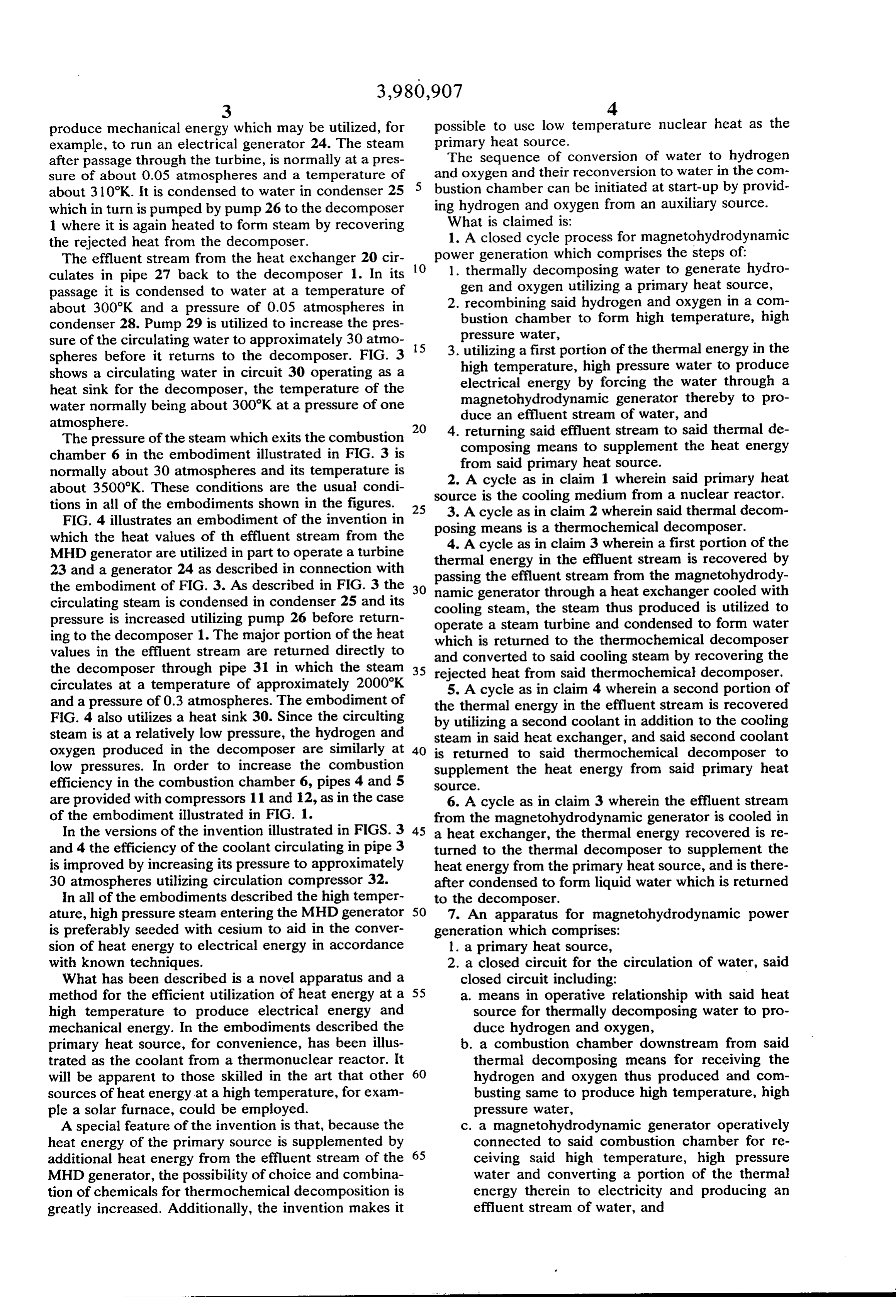
FIG. 4 illustrates an embodiment of the invention in which the heat values of th effluent stream from the posing means is a thermochemical decomposer. MHD generator are utilized in part to operate a turbine thermal 4. A cycle as in claim 3 wherein a first portion of the 23 and a generator 24 as described in connection with passing the energy in the effluent stream is recovered by effluent stream from the magnetohydrody the embodiment of FIG. 3. As described in FIG. 3 the 30 namic generator through a heat exchanger cooled with circulating steam is condensed in condenser 25 and its cooling steam, the steam thus produced is utilized to pressure is increased utilizing pump 26 before return ing to the decomposer 1. The major portion of the heat operate a steam turbine and condensed to form water which is returned to the thermochemical decomposer values in the effluent stream are returned directly to and converted to said cooling steam by recovering the the decomposer through pipe 31 in which the steam 35 rejected heat from said thermochemical decomposer. circulates at a temperature of approximately 2000°K 5. A cycle as in claim 4 wherein a second portion of and a pressure of 0.3 atmospheres. The embodiment of the thermal energy in the effluent stream is recovered FIG. 4 also utilizes a heat sink 30. Since the circulting by utilizing a second coolant in addition to the cooling steam is at a relatively low pressure, the hydrogen and steam in said heat exchanger, and said second coolant oxygen produced in the decomposer are similarly at 40 is returned to said thermochemical decomposer to low pressures. In order to increase the combustion supplement the heat energy from said primary heat efficiency in the combustion chamber 6, pipes 4 and 5 SOC.
are provided with compressors 11 and 12, as in the case 6. A cycle as in claim 3 wherein the effluent stream of the embodiment illustrated in FIG. 1. from the magnetohydrodynamic generator is cooled in In the versions of the invention illustrated in FIGS. 3 45 a heat exchanger, the thermal energy recovered is re and 4 the efficiency of the coolant circulating in pipe 3 turned to the thermal decomposer to supplement the is improved by increasing its pressure to approximately heat energy from the primary heat source, and is there 30 atmospheres utilizing circulation compressor 32. after condensed to form liquid water which is returned In all of the embodiments described the high temper to the decomposer.
ature, high pressure steam entering the MHD generator 50 7. An apparatus for magnetohydrodynamic power is preferably seeded with cesium to aid in the conver generation which comprises:
sion of heat energy to electrical energy in accordance 1. a primary heat source, with known techniques. 2. a closed circuit for the circulation of water, said What has been described is a novel apparatus and a closed circuit including:
method for the efficient utilization of heat energy at a 55 a means in operative relationship with said heat high temperature to produce electrical energy and source for thermally decomposing water to pro mechanical energy. In the embodiments described the duce hydrogen and oxygen, primary heat source, for convenience, has been illus b. a combustion chamber downstream from said trated as the coolant from a thermonuclear reactor. It thermal decomposing means for receiving the will be apparent to those skilled in the art that other 60 hydrogen and oxygen thus produced and com sources of heat energy at a high temperature, for exam busting same to produce high temperature, high ple a solar furnace, could be employed. pressure water,
A special feature of the invention is that, because the c. a magnetohydrodynamic generator operatively heat energy of the primary source is supplemented by connected to said combustion chamber for re additional heat energy from the effluent stream of the 65 ceiving said high temperature, high pressure MHD generator, the possibility of choice and combina water and converting a portion of the thermal tion of chemicals for thermochemical decomposition is energy therein to electricity and producing an greatly increased. Additionally, the invention makes it effluent stream of water, and
Page 6
d. means for returning the water from the magneto ing thermal energy from said effluent stream, to hydrodynamic generator to the thermal decom said thermochemical decomposer to supplement posing means to supplement the heat energy the heat energy from the primary heat source, and from the primary heat source. 3. a condenser to convert the steam in the effluent 8. An apparatus as in claim 7 wherein the said pri stream to water, said condenser being operatively mary heat source is the cooling medium from a nuclear connected to said thermochemical decomposer for reactor. conducting the water to the decomposer. 9. An apparatus in claim 8 wherein said thermal 13. A cycle as in claim 1 wherein said thermal de decomposing means is a thermochemical decomposer. 10 composing means is a thermochemical decomposer. 10. An apparatus as in claim 9 further including - 14. A cycle as in claim 1 wherein a first portion of the 1. a heat exchanger including means for conducting thermal energy in the effluent stream is recovered by cooling steam therethrough to extract a portion of passing the effluent stream from the magnetohydrody the thermal energy from said effluent stream and namic generator through a heat exchanger cooled with convert said coolant steam into superheated steam, 15 cooling steam, the steam thus produced is utilized to 2. a steam turbine operatively connected to said operate a steam turbine and condensed to form water steam conducting means to produce mechanical which is returned to the thermal decomposer and con energy and steam at lower temperature and pres verted to said cooling steam by recovering the rejected Sure, heat from said thermal decomposer. 3. a condenser for converting said steam at lower 20 15. An apparatus as in claim 7 wherein said thermal temperature and pressure to liquid water, and decomposing means is a thermochemical decomposer. 4. means for returning said liquid water to the ther 16. An apparatus as in claim 7 further including: mochemical decomposer for converting it to cool 1. a heat exchanger including means for conducting ant steam by recovering the rejected heat from said cooling steam therethrough to extract a portion of
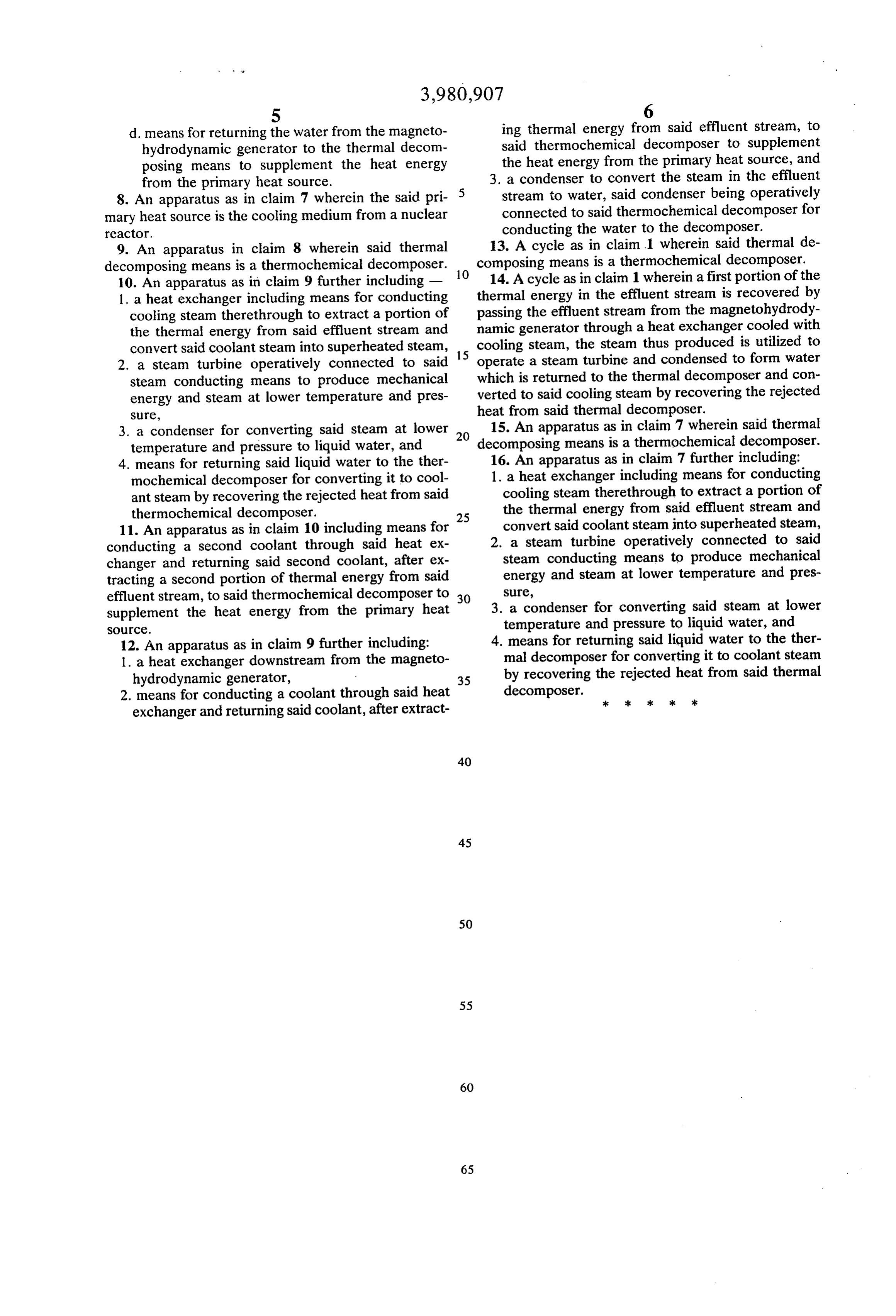
the thermal energy from said effluent stream and 11. An apparatus as in claim 10 including means for convert said coolant steam into superheated steam, conducting a second coolant through said heat ex 2. a steam turbine operatively connected to said changer and returning said second coolant, after ex steam conducting means to produce mechanical tracting a second portion of thermal energy from said energy and steam at lower temperature and pres effluent stream, to said thermochemical decomposer to 30 Sure, supplement the heat energy from the primary heat 3. a condenser for converting said steam at lower SOCC. temperature and pressure to liquid water, and 12. An apparatus as in claim 9 further including: 4. means for returning said liquid water to the ther 1. a heat exchanger downstream from the magneto mal decomposer for converting it to coolant steam hydrodynamic generator, 35 by recovering the rejected heat from said thermal 2. means for conducting a coolant through said heat decomposer. sk >k sk sk k exchanger and returning said coolant, after extract
Provenance
- Collection
- Cited prior art
- Original PDF
- patentimages.storage.googleapis.com →
- Filed
- 1975-01-13
- Pages
- 6
- Method
- pdftotext (the PDF's own text layer) + pdftoppm 300dpi page scans
- Source
- Google Patents bibliographic record
- Granted
- 1976-09-14
- Inventors
- Takashi Nakamura; Asahi Kasei Kogyo KK
- Transcribed from
- patentimages.storage.googleapis.com →