patent · US3946721
Method of collecting and storing solar heat
30 March 1976
Page 1 — bibliographic record
United States Patent (19) [11] 3,946,721 Keyes et al. (45) Mar. 30, 1976 54 METHOD OF COLLECTING AND STORING and Ventilating, Oct. 1955, pp. 92-97. SOLAR HEAT "Solar Energy Heating,' Mechanical Engineering, Feb. 75) Inventors: John Harold Keyes; Charles Irvin 1950, pp. 153-155.
Strickland; Robert George
Strickland, all of Nederland, Colo. Primary Examiner-Kenneth W. Sprague (73) Assignee: International Solarthermics Assistant Examiner-James C. Yeung Corporation, Nederland, Colo. Attorney, Agent, or Firm-Burton, Crandell & Polumbus
(21) Appl. No.: 515,234 57 ABSTRACT Related U.S. Application Data The method of collecting, storing and transmitting 62) Division of Ser. No. 445,473, Feb. 25, 1974. solar heat includes the steps of absorbing solar heat on a collector surface wherein the collector surface is in 52 U.S. Cl................... 126/270; 165/18; 237/1 A; sulated from the ambient environment, passing air 126/400 across the collector surface in a heat transfer process (51) Int. Cl'............................................. F24, 3/02 whereby the heat absorbed by the collector surface is (58) Field of Search...... 126/270, 271, 400; 165/18; transferred to the air, passing the hot air leaving the 237/1 A collector surface through a horizontal duct disposed at
a lower elevation than the collector surface, and pass ing the hot air flowing from the duct into an elevated
UNITED STATES PATENTS storage chamber containing material with heat absor 965,391 7/1910 Little .................................. 23711 A bent and heat retaining characteristics whereby the 1,889,238 1 1/1932 Clark.................................. 126/271 heat in the hot air is transferred from the hot air to the 2,680,437 6/1954 Miller................................. 26/270 material and retained by said material until it is re 2,680,565 6/1954 Lof................................. 126/271 X moved therefrom by a relatively cool air flow. OTHER PUBLICATIONS 3 Claims, 27 Drawing Figures "Fully Solar-Heated House,' Air Conditioning, Htg
Page 2
Drawing sheet — no readable text.
Page 3
Drawing sheet — no readable text.
Page 4
Drawing sheet — no readable text.
Page 5
Drawing sheet — no readable text.
Page 6
Drawing sheet — no readable text.
Page 7
Drawing sheet — no readable text.
Page 8
It is another object of the present invention to pro
METHOD OF COLLECTING AND STORING vide a solar heating unit which utilizes a small and SOLAR HEAT compact heat collector yet has the capacity for ade
REFERENCE TO RELATED APPLICATIONS
quately heating typical residential building structures.
It is another object of the present invention to pro vide a solar heating apparatus having a reflective panel
This application is a division of Application Ser. No.
445,473 filed Feb. 25, 1974. to increase captured solar radiation and which can also
BACKGROUND OF THE INVENTION
serve as a protective covering for the collector portion of the apparatus in inclement weather conditions.
O It is another object of the present invention to pro 1. Field of the Invention
The present invention relates generally to a method vide a solar heating method and apparatus wherein and apparatus of collecting, storing and transmitting conventional valve means between a collector and solar heat and more particularly relates to a method storage chamber of the apparatus are eliminated and apparatus for heating building structures and the through the unique positioning and types of air transfer 15 ducts and baffles.
like.
2. Description of the Prior Art It is another object of the present invention to pro The tremendous energy output of the sun has been vide a hot air solar furnace in which baffle members are recognized for many years and numerous attempts positioned on the collector and in the heat storage have been made at harnessing this energy so that it can 20 chamber to desirably circulate air in obtaining opti be converted into a useful state. For example, the sun's mum temperature outputs from the unit. energy has been successfully converted into electrical It is another object of the present invention to pro energy with solar batteries and similarly, the sun's en vide a hot air solar furnace in which air is transferred ergy has been converted into heating systems by so from a solar heat collector to a storage chamber with a called solar stoves, furnaces and the like. The solar minimum of heat loss and removed from the storage furnace apparatusses, however, have been typified by 25 chamber and transmitted into a building structure with extremely large collector plates covering large portions a minimum heat loss.
of the roof structure of a building to be heated with the It is another object of the present invention to pro apparatus and large storage chambers usually in the vide a hot air solar furnace which has above ground substructure of the building wherein the heat is stored 30 heat storage eliminating the need for costly and disfig after having been transferred from the collector by a uring excavation.
liquid fluid medium. The heat in the storage chamber is It is another object of the present invention to pro then circulated through the building structure by a vide means to containerize heat storage with a new and separate fluid flow. simplified framing technique. These systems, which have not only been unwieldly 35 SUMMARY OF THE INVENTION and very expensive to install, have proven to be very inefficient in that there is an excessive heat loss when The foregoing and other objects are obtained in ac transferring the solar heat from the collector to the cordance with the present invention whereby solar heat removed storage chamber. Furthermore, these systems is collected and stored in an integrated compact unit have not been capable of being easily installed in exist 40 which is capable of generating a heat flow equal to or ing building structures and have not been devised to surpassing those of much larger unwielding units which cooperate as an auxiliary heating unit to the conven have been typical of prior art solar heating units. The tional forced air heating systems commonly found in solar heating apparatus of the present invention is self building structures. contained in an elongated housing preferably of triang Typical examples of prior art solar heating systems 45 ular transverse cross-sectional configuration. This con may be found in the June, 1973 and October, 1973 figuration has been found to allow a minimum quantity issues of Popular Mechanics magazine and in the May, of heat retaining material, such as gravel, to be stored 1973 issue of Popular Science magazine. in the apparatus with a minimum of structural rein
OBJECTS OF THE INVENTION
forcement. The housing is basically constructed of two rectangular top panels, a rectangular bottom panel, and
The present invention has for its primary object the 50 two triangular end panels which are interconnected to provision of a new and improved method and apparatus define an enclosed storage chamber for the heat retain for collecting, storing and transmitting solar heat. ing material. The panels are each laminated in such a It is another object of the present invention to pro manner as to give both structural strength and the re vide a compact, self-contained solar heating unit which quired insulating qualities for maintaining the tempera can be positioned exteriorly of a building structure and 55 ture of the heat retaining material in the storage cham with minimum time and expense connected to the ber. A collector unit is mounted upon one of the top building structure so as to convert solar radiation into panels of the housing so as to be inclined relative to the heat for maintaining a desired temperature within the vertical in a position to receive the maximum heat from building structure. the Winter sun.
It is another object of the present invention to pro 60 The collector unit is uniquely designed to absorb vide a new and improved solar heating system which is solar radiated heat and retain the heat by converting readily connected into an existing forced air heating the heat waves, which will readily pass through trans system so as to serve as an auxiliary heating system with parent glass or plastic panes on the collector face, into minimum alteration to an existing building structure. 65 long wave heat radiation which will not readily pass It is still another object of the present invention to back through the glass or plastic panes on the face of provide a new and improved solar heating system the collector. The solar heat is absorbed on a base which can also serve as a cooling system with minimal panel of the collector which emits relatively long wave physical or mechanical alterations. heat radiation that becomes trapped in the collector.
Page 9
The base panel of the collector has a plurality of for As will be more fully appreciated hereinafter, the wardly opening cups which serve to increase the heat unit is ideally suited for connection to an existing absorption and emission capability of the collector. forced air heating system in a building structure so as to Depending upon the material from which the cups are serve as an auxiliary unit to the forced air heating sys made, they usually will not retain the heat imparted tem even though in many instances, the solar heating thereto by the solar radiation for extended periods of unit is sufficient in itself to provide the necessary heat time; accordingly, air is circulated through the collec for the building structure.
tor to transfer the heat absorbed by the cups into the According to the method of the present invention, storage chamber of the apparatus wherein the gravel 10 heat is first absorbed from the sun on a collector sur material not only absorbs the heat carried by the air but face wherein the collector surface is insulated from the also retains the heat for extended periods of time due to ambient environment and internal air is passed across inherent heat retaining characteristics of gravel and its the collector surface in a heat transfer process so that inherent restriction of convection. The air which passes the heat absorbed by the collector surface is trans through the collector and into the storage chamber is 15 ferreda duct to the internal air. The air is then passed through which is lower than the collector surface into a re-circulated through the collector so as to continu ously transfer heat, when desired, from the collector to raised storage chamber wherein it is directed through the storage unit. For purposes of the present disclosure, heat absorbent and heat retaining material in the stor this circulating air will be referred to as conditioning age chamber so that the heat in the hot air is trans air. Since it is important to the optimum operation of ferred to the material in the storage chamber. The heat the unit that the conditioning air be equally exposed to retained by the material in the storage chamber is the entire base of the collector, a series of baffles are transferred into a building structure by directing a util provided in the collector to direct the air stream ity stream of air through the material in the storage through a series of reversing bends. Similarly, baffles chamber and into the building structure wherein it is are provided in the storage chamber to direct the con 25 distributed as desired throughout the structure. Other objects, advantages and capabilities of the ditioning air throughout the entire quantity of gravel in present invention will become more apparent as the the storage chamber.
A conditioning air pump is positioned within the descriptionaccompanying proceeds taken in conjunction with the drawings.
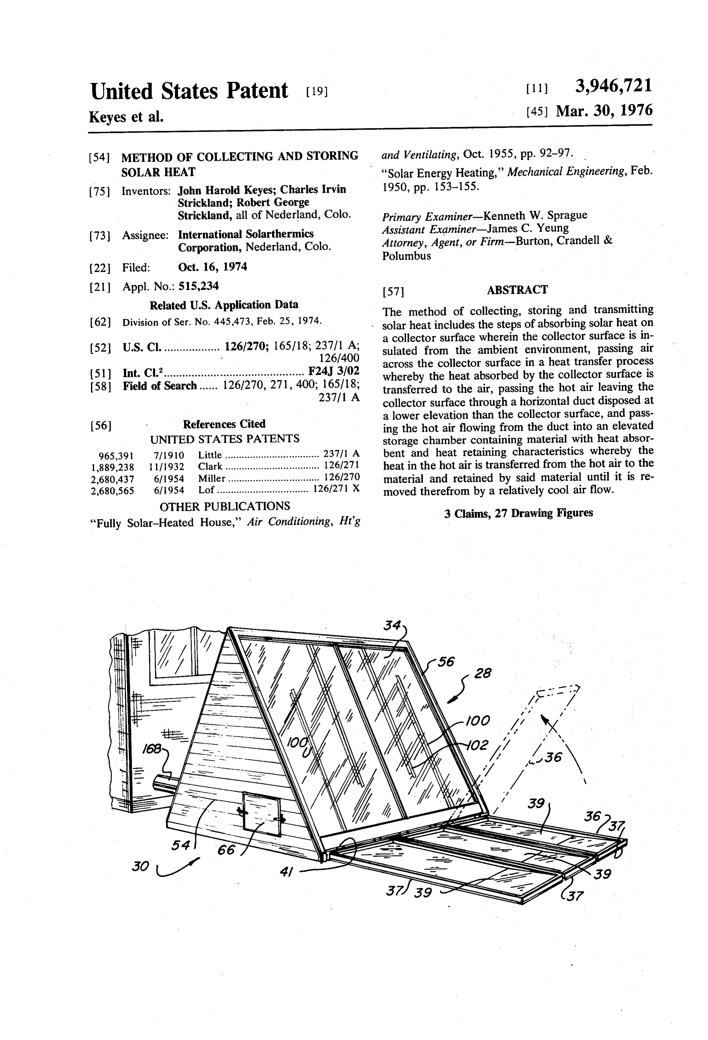
storage chamber to effect the desired conditioning air flow. The air is passed from the storage chamber to the 30 DESCRIPTION OF THE DRAWINGS collector and back into the storage chamber through FIG. 1 is a perspective view of the solar heating appa inlet and outlet ducts which are positioned at an eleva ratus tion below both the storage chamber and the collector shownofinthe an present invention with the reflector panel open position.
so that when the pump is not in operation, the hot air which is lighter than cold air, and therefore urged to 35 of FIG. 1 withperspective
FIG. 2 is a the view of the solar heating unit reflector panel in a closed position.
the top of the respective components of the apparatus, FIG. 3 is a perspective view of the solar heating unit will not be able to freely flow between the components of the present invention as viewed from the reverse side so that the ducts establish thermal traps that avoid the of FG 1.
necessity of relatively expensive valve means to accom FIG. 4 is an end elevation of the solar heating unit of plish the same purpose. 40 F.G.
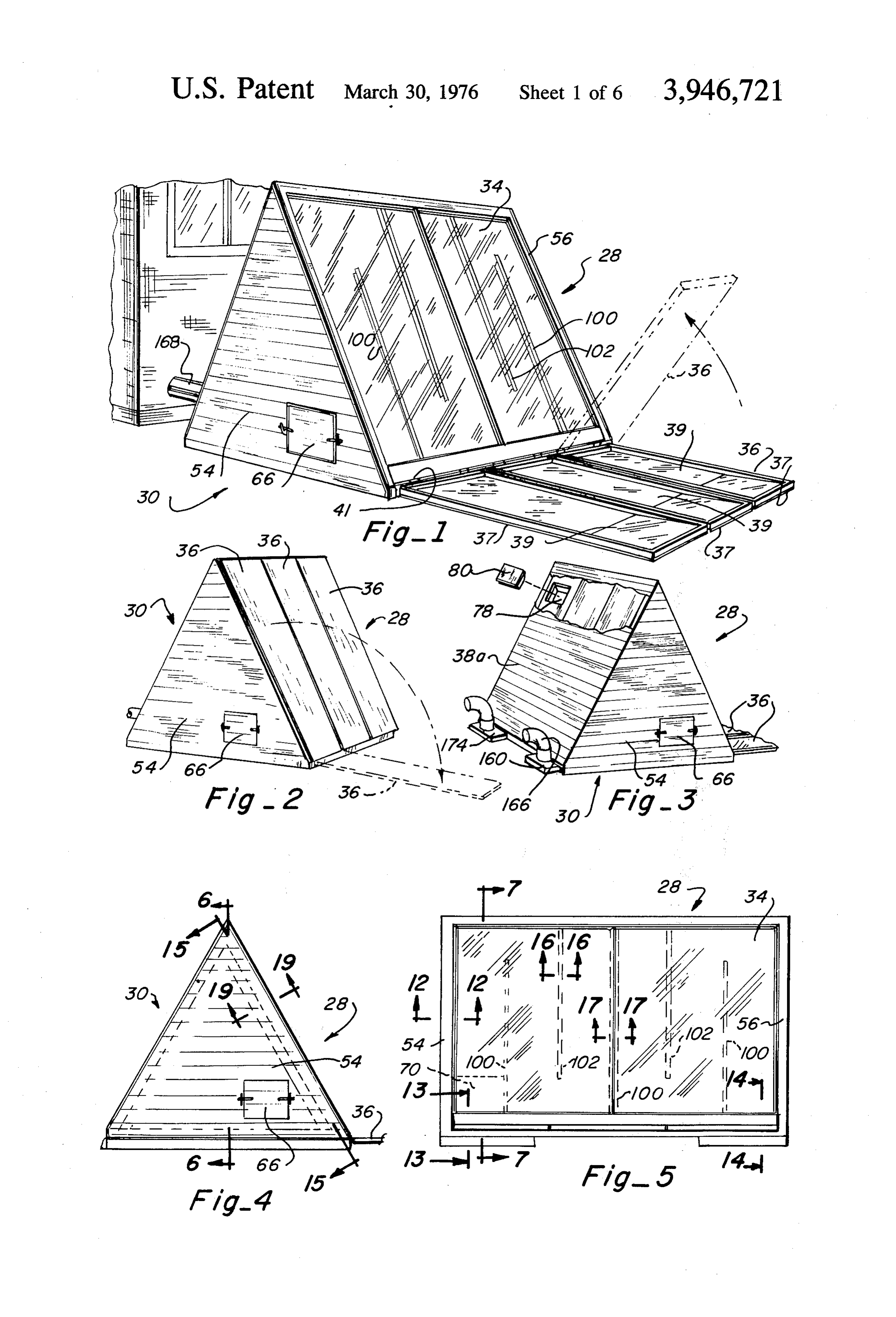
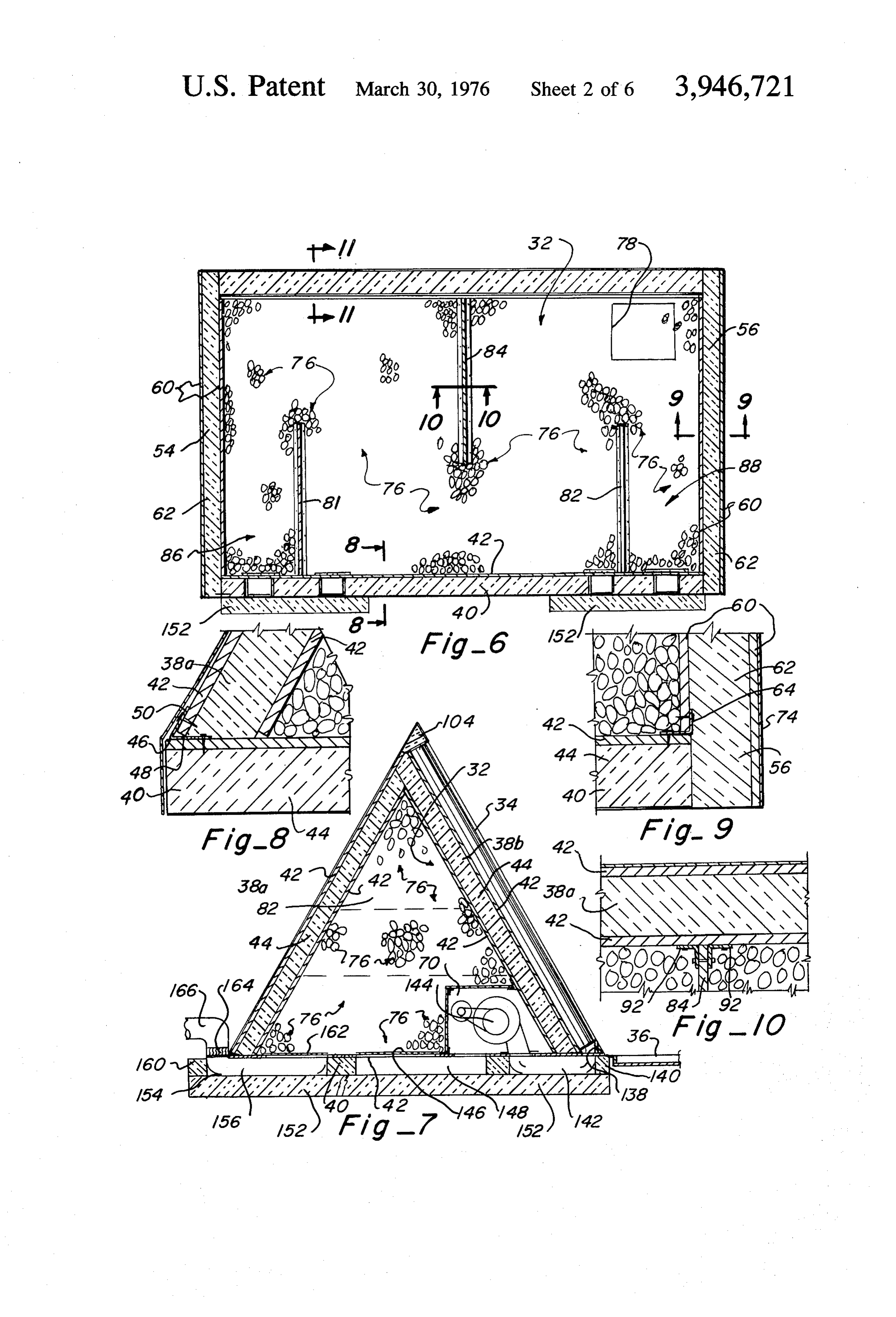
A reflector panel is hinged to the framework of the FIG. 5 is a side elevation of the solar heating unit of housing along an edge of the collector unit so that by FIG. 1 showing the collector unit. opening the reflective panel, the solar heat radiation FIG. 6 is an enlarged vertical section taken along line being absorbed by the collector unit is increased. This 6-6 of FIG. 4.
reflective panel is designed so that in a closed position 45 FIG. 7 is an enlarged vertical section taken along line it overlies the collector unit and thereby protects the 7-7 of FIG. S.
relatively fragile glass from detrimental environmental FIG. 8 is an enlarged fragmentary vertical section elements such as hail, sunlight in Summer months, and illustrating the connection of a top panel of the solar the like. heating unit to the bottom panel. The heat retained by the heat retaining material in 50 FIG. 9 is an enlarged fragmentary section illustrating the storage chamber is transferred into an adjacent the connection of an end panel of the solar heating unit building structure or the like by a utility pump which to the bottom panel.
may also be positioned within the storage chamber and FIG. 10 is a section taken along line 10-10 of FIG. connected to the building structure by suitable insu 6.
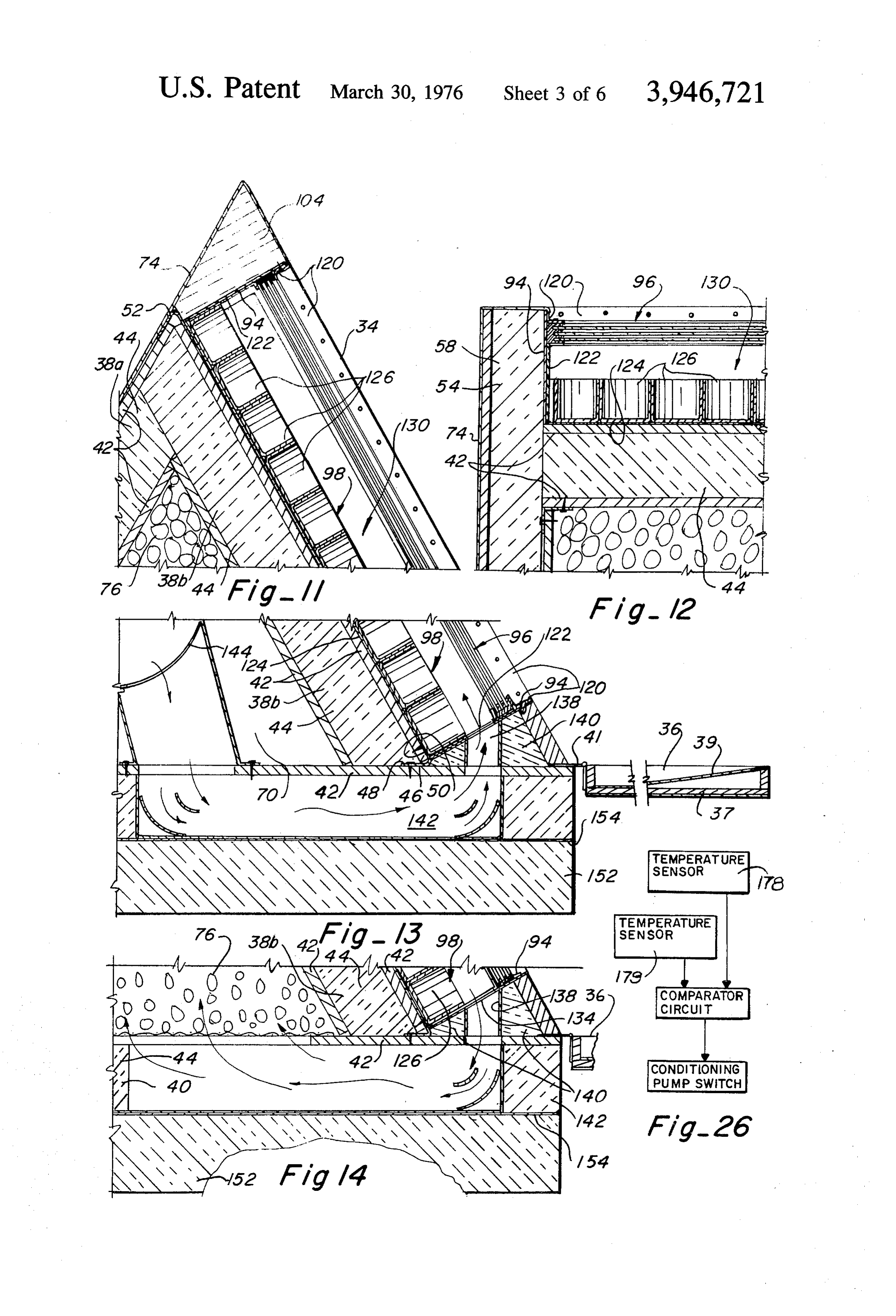
lated duct work having outlets for selectively distribut 55 FIG. 11 is an enlarged framentary vertical section ing the hot air through the building structure. This air taken along line 11-11 of FIG. 6.
flow, which will be hereinafter referred to as the utility FIG. 12 is an enlarged section taken along line air flow, is circulated back through the storage cham 2-2 of FIG.S.
ber in a manner so as to obtain a maximum heat trans FIG. 13 is a vertical section taken along line 13-13 fer from the heat retaining material to the air and in a 60 of FIG.S.
manner such that the utilitiy air is not short circuited Fig. 14 is a vertical section taken along line 14-14 and directed through the collector with the condition of FIG. 5.
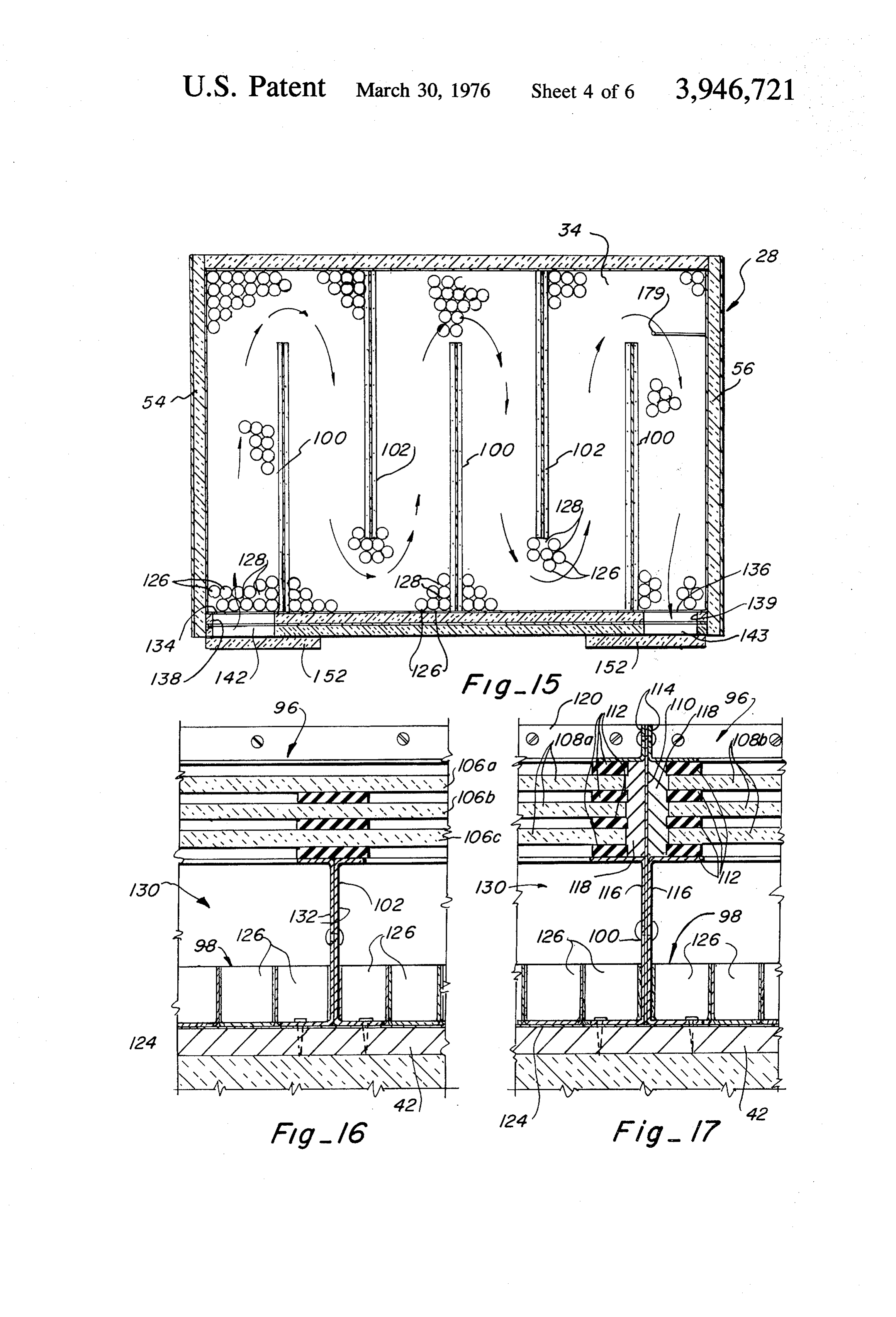
ing air unless both pumps are operating simultaneously. FIG. 15 is a section taken along line 15-15 of FIG. As will be explained in more detail hereinafter, this is 4.
accomplished by positioning the inlet and outlet ducts 65 FIG. 16 is a section taken along line 16-16 of FIG. for both the conditioning air circuit and the utility air 5.
circuit on appropriate sides of the baffle members FIG. 17 is a section taken along line 17-17 of FIG.
Page 10
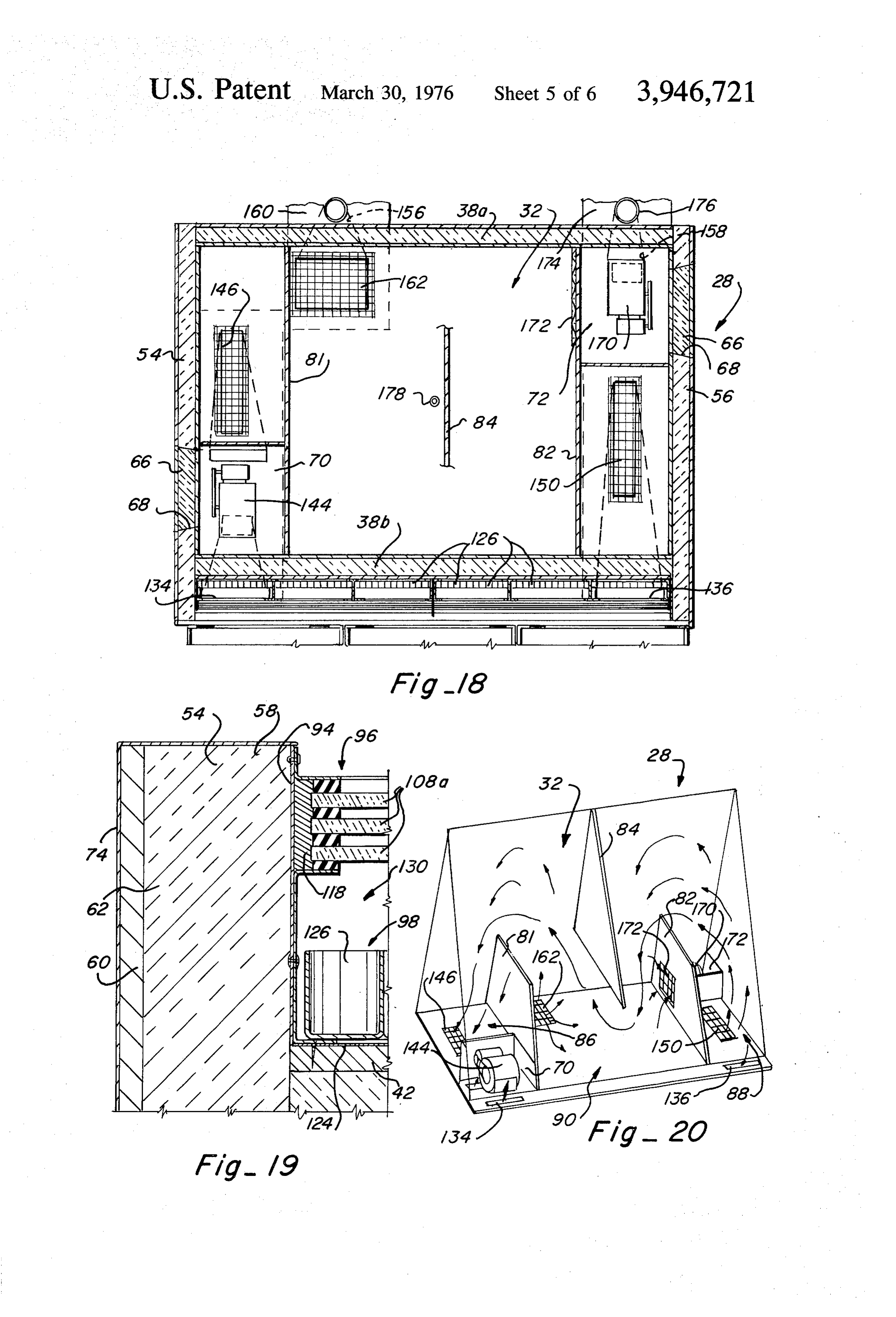
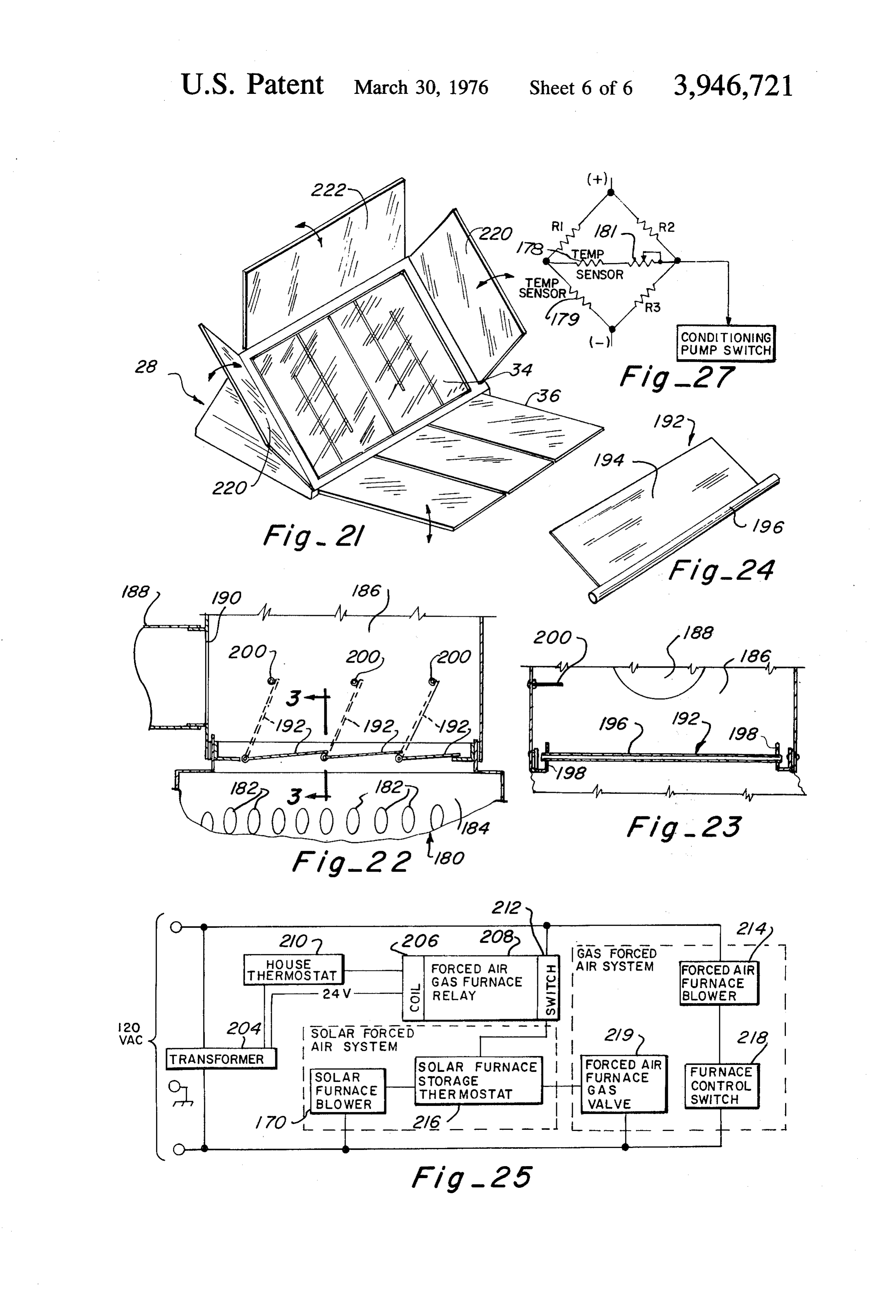
FIG. 18 is a diagrammatic horizontal section illustrat and reliably interconnect the panels. The bottom panel ing the floor plan of the solar heating apparatus of the extends beyond the lower edge of the top panel 38b for present invention. a reason which will become clear later. FIG. 19 is an enlarged section taken along line At the juncture of the upper edges of the top panels 19-19 of FIG. 4. 38a and 38b, one of the top panels 38a extends across FIG. 20 is a diagrammatic perspective view illustrat the upper end of the other top panel38b and is bevelled ing the air currents through the storage chamber of the at its outer end so as to form a 60 angle therewith and solar heating apparatus of the present invention. establish a smooth juncture of the two panels. The FIG. 21 is a diagrammatic perspective view showing 10 plywood laminate 42 on the outer surface of each of a modified form of the solar heating unit of the present the top panels extends upwardly to the uppermost point invention. of the housing and an angle iron strip 52 is placed FIG. 22 is an enlarged vertical section taken through downwardly over the juncture of the two outermost an upper portion of a forced air furnace illustrating the plywood sheets to extend along the length of the pan connection of the solar heating apparatus of the pre 15 els. This angle iron strip 52 is suitably fastened to the sent invention to the forced air furnace. respective top panels, such as with screw type fasten ers,
FIG. 23 is a section taken along line 23-23 of FIG. thereof. to reliably secure the panels along the top edges
FIG. 24 is a perspective view of a valve plate shown Triangular shaped end panels 54 and 56 are secured in FIGS. 22 and 23. to the end edges of the top and bottom panels 38a and FIG. 25 is a circuit diagram of the connection of the 20 38b of the housing in a manner which is best illustrated solar heating apparatus of the present invention to a in FIG. 9. There it will be seen that the end panels 54 conventional forced air furnace system. and 56 extend downwardly to the lower edge of the FIG. 26 is a diagrammatic representation of the dual bottom panel 40 and likewise extend outwardly to the switch control for the conditioning pump of the appara 25 outer edges of the top panels 38a and 38b to com tus of the present invention. pletely cover the end edges of the top and bottom pan FIG. 27 is an electrical schematic of the dual switch els. The end panels actually extend beyond the top panel 38b at 58, FIGS. 12 and 19, for a purpose to be control of FIG. 26.
described later. The end panels are constructed identi
DESCRIPTION OF THE PREFERRED cally to the top and bottom panels in that they are EMBODIMENTS 30 laminates having outer layers 60 of a rigid material The solar heating apparatus 28 of the present inven such as plywood and an inner insulating rigid foam core tion includes a housing 30 defining an internal storage 62. The end panels are connected to the top and bot chamber 32, a collector unit 34 mounted upon one face tom panels by angled metallic strips 64, FIG. 9, which of the housing 30, and a reflector panel 36 pivotally 35 extend along the junctures of the panels and are fas connected to the housing so as to be movable between tened thereto as with screw-type fasteners in a self an open position exposing the collector unit 34 to the tightening manner. Each end panel has a removable ambient environment and a closed protective position door 66 closing an opening 68 therein which provides overlying the collector unit. selectable access to pump containing compartments 70 The framework for the apparatus includes three insu 40 and 72 in the storage chamber 32 which will be de lating rectangular panels of substantially the same size scribed later.
which are interconnected along their longitudinal A water-repellant sheet metal covering 74 is pro edges to form an elongated housing of triangular trans vided over the top panel 38a and the end panels 54 and verse cross-section. The three rectangular panels con 56 so that these panels will be protected from deterio sist of two inclined top panels 38a and 38b and a floor 45 ration by moisture in the ambient environment. The top, bottom and end panels cooperate in confin panel 40 with the top panels 38a and 38b forming an angle of approximately 60' with horizontal. Each of the ing a heat retaining material 76 such as gravel in a top panels and bottom panel are laminated with con manner such that the weight of the gravel does not ventional plywood sheets 42 on opposite faces and an place excessive outward pressure on the housing. In inner relatively thick core 44 of an insulating material other words, since gravel is naturally piled with inclin such as a rigid polyurethane foam. The plywood panels 50 ing sides, the pressure on the top walls 38a and 38b of are preferably painted or coated with a reflective paint the housing, since they too are inclined, is minimal. In such as a silver paint to better retain heat within the the preferred form, the heat retaining material 76 is a granite rock of approximately 1% inches in diameter so storage chamber.
The panels 38a, 38b, and 40 are connected along that the spaces between the rock particles are sufficient their edges with a relatively thin gauge angled metallic 55 to allow the flow of air through the storage chamber. A strip which is positioned to be self-tightening. Referring fill opening 78, FIGS. 3 and 6, is provided near the top to FIG. 8, it will be seen that the lower edge of each top edge of one of the top panels so that gravel can be panel is tapered to fit flush against the horizontal top poured through the opening to fill the storage chamber. surface of the bottom panel 40 and an angled metallic An insulated door 80 removably seals the opening 78 strip 46, FIGS. 8 and 13, is positioned along the outer 60 during operation of the apparatus. edge of the top and bottom panels 38a and 38b so as to The storage chamber 32 of the apparatus has a plu have a horizontal leg 48 which lies between the panels rality of baffles or barrier plates 81, 82 and 84 posi and an upwardly inclined leg 50 which is flush with the tioned therein to encourage the desired circulation of outer surface of the top panel. Conventional fasteners, 65 air through the gravel material as will be described in such as of the screw type, connect the horizontal leg more particularity later. The baffle members include with the bottom panel and the upwardly inclined leg two upstanding baffle members 81 and 82 of trapezoi with the top panel. These fastening strips 46 extend dal configuration which are flush with the bottom wall along the length of the bottom of the panels to securely and extend slightly over half the height of each of the
Page 11
top panels thereby separating the lower portion of the similarly sandwiched between an outer angle iron strip storage chamber into two end sections 86 and 88 and a 120 and an inner channel member 122 each of which central section 90, FIGS. 6 and 20. The third depend are affixed in any suitable manner to the outer frame 94 ing baffle member 84 is suspended from the upper of the collector unit. Accordingly, the glass panels 108a portion of the top panel members at approximately and 108b on each half of the glass insulating portion of their longitudinal center and is of triangular configura the collector unit are retained in parallel spaced rela tion to fit flushly against the inner surfaces of the top tionship and are sealed around their periphery to pre panel members and extend slightly over half the height vent heat loss.
of the top panel members so as to overlap the upward The heat accumulator portion 98 of the collector unit extent of the upstanding baffles. Each of the baffle 10 includes a planar back plate 124, preferably a sheet of members is secured to the abutting top and bottom black coated metallic coil or the like which lies against panel members by suitable fasteners 92, FIG. 10, which or is affixed to the outer plywood sheet 42 of the top could be angle iron strips. panel 38b. A pluralty of forwardly opening cups 126, The reflector panel 36 in the preferred form includes preferably of cylindrical configuration and made of a framework 37 in which three highly reflective sheets 15 aluminum and coated black, are positioned upon the 39 of aluminum or the like are retained. The sheets black aluminum back sheet and define spaces 128 may follow a modified parabolic curve to concentrate therebetween which expose the back sheet 124. Again, solar radiation on the collector unit 34. The framework preferably the cups are coated or annodized in a black 37 is pivotally mounted as by a hinge 41 to the floor color as black is known to be the best heat absorbent panel 40 of the apparatus. The reflective sheets, of 20 color. The cups may be loosely disposed upon the back course, could be other suitable materials such as mir plate 124 or could be secured thereto if desired. It will rors, or the like, and if the mirrors were readily suscep be appreciated that the cups enlarge the surface area of tible to breakage, a large number of relatively small the heat accumulator 98 and thus the solar thermal mirrors could be mounted in the framework 37 so that energy capturing ability of the apparatus. In fact, by replacement of damaged or broken mirrors would not 25 using cups which are approximately 2 inches in length be a great economical burden. and 2% inches in diameter, the surface area of the heat The collector unit 34 which is probably best illus accumulator will be increased approximately 4.75 trated in FIGS. 1, 5, 7 and 11-14, is of a size substan times over that of a planar heat accumulator. As clearly tially the same as the top panels of the housing and is seen in FIGS. 11-13, the forward extent of the accumu mounted directly on the outer face of the top panels 30 lator cups 126 is rearwardly spaced from the insulator 38b. The collector unit includes an outer peripheral glass 96 defining an open space or passage 130 therebe rigid frame 94, a front insulating glass portion 96, and tween through which air can freely pass. The baffle a back heat accumulator portion 98. The insulator glass members 100 and 102 are positioned within this space portion and heat accumulator portion are separated by to direct the conditioning air currents along a predeter a plurality of baffle members 100 and 102 which, as 35 mined path which fairly uniformaly covers the entire will be explained hereinafter, serve to circulate air array or matrix of accumulator cups whereby a com uniformly through the collector. plete and effective transfer of heat from the accumula The peripheral frame 94 abuts the inner surfaces of tor cups to the air can be effected.
the extensions 58 of the end panels beyond top panel As best illustrated in FIG. 15, in the preferred form, 38b so as to be insulated along the associated two sides 40 there are three rising baffle members 100 which extend from the ambient environment and an elongated wedge upwardly from the lower edge of the collector unit in shaped insulating block 104 lies across and is attached uniformly spaced relationship and two depending baf to the top portion of the peripheral frame to insulate fle members 102 which extend downwardly from the the top portion from the ambient environment. top edge of the collector unit into the centralmost The insulating glass portion 96 of the collector unit 45 spaces between the three rising baffle members. Each consists, in the preferred form, of three spaced layers of the baffle members extend approximately three 106a, 106b and 106c of glass with each layer of glass fourths of the height of the collector. Referring to having two coplanar glass or plastic panels 108a and FIGS. 16 and 17, these baffle members can be seen to 108b separated at the longitudinal center of the collec be comprised of the back-to-back channel members tor by a center plate 110. Each glass or plastic panel is 50 132 and 116 with the channel members 116 on the separated from the glass panel in the next adjacent center baffle 100 being those at the longitudinal center layer by a rubber sealant strip 112 which extends of the collector unit which support the adjacent center around the periphery of the panel. Referring to FIG. edges of the glass panels 108a and 108b. The remaining 17, the rubber sealant strips extending along the adja baffle members, as shown in FIG. 15, serve to support cent ends of the glass panels at the longitudinal center 55 the glass panels and additional rubber spacer sealant of the collector are seen sandwiched with the glass strips at intermediate locations so that the glass insulat panels between an outer angle iron strip 114 which is ing portion 96 of the collector unit is adequately sup secured as by a rivet to the center plate 110 and an ported and less prone to damage. Of course, each of the inner channel member 116 which is also secured to the baffles are secured to the back plate and the underlying center plate as by a rivet. The periphery of each glass 60 plywood sheet of the top panel by suitable fasteners. panel is embedded along with the rubber sealant strips Referring now to FIGS. 13-15 and 20, it will be seen 112 in a caulking compound 118, FIG. 17, to hermeti that the lower horizontal portion of the frame 94 of the cally seal the perimeter of the insulating glass portion collector unit has rectangular openings 134 and 136 at of the collector so that heat accumulated in the heat opposite ends thereof which communicate with the accumulator portion of the collector cannot escape 65 space 130 between the glass insulator section and the back to the ambient environment around the periphery heat accumulator section of the unit. The opening 134 of the glass panels. In FIGS. 11-13, the top, bottom and is the inlet opening to the collector while the opening side edges respectively of the glass panels are seen 136 is the outlet opening. Air entering the collector
Page 12
through the inlet opening 134 is confined in the space be used. Preferably, a vapor barrier 154 in the form of 130 between the glass insulator portion 96 and heat a corregated metal or plastic sheet would separate the accumulator portion 98 and is directed along a path insulating panel from the bottom panel and the ducts to defined by the baffle members which passes through a prevent the ingress of moisture.
series of reversing bends as indicated by the arrows in The flow of conditioning air through the storage FIG. 15, thereby forcing the air to pass across all of the chamber of the apparatus is best illustrated in FIG. 20 accumulator cups in the collector. Turbulence created wherein it is seen that hot air leaving the collector unit by the configuration and positioning of the cups assists through the outlet opening 136 emerges through the in the more efficient transfer of heat. screened opening 150 at the inlet end of the storage Referring now to FIGS. 7, and 13-15, it will be seen 10 chamber and is forced to pass unwardly over the baffle that the inlet and outlet openings 134 and 136 respec member 82 into the heat retaining gravel and then tively of the collector unit are connected through rect follow a downwardly and upwardly reversing path angular passages 138 and 139 in an insulating foam below and above the three baffle plates 80, 82 and 84 block 140 to insulated ducts 142 and 143 which are cut in the storage chamber until it is drawn downwardly or otherwise formed in the floor panel 40 of the hous 15 through the screened outlet opening 146 at the oppo ing. The ducts 142 and 143 open into the storage cham site end of the storage chamber and subsequently ber 32 of the apparatus. The duct 142 communicating blown by the conditioning pump into the collector unit with the inlet opening 134 of the collector unit is in through the inlet opening 134. In this manner, the hot fluid communication with a conditioning air pump 144 20 air being directed into the storage chamber from the mounted within the enclosed compartment 70 in the collector unit is forced to pass through the storage storage chamber. The pump 144 is also in fluid commu chamber in such a manner as to come into contact with nication with an outlet 146 from the storage chamber substantially all of the heat retaining gravel material in via a duct 148. The ducts 143 and 148 each have the storage chamber. It should be realized that the inlet screens covering their openings into the storage cham 25 end of the storage chamber will normally be substan ber 32 and each screen has a mesh size less than the tially hotter than the outlet end during operation of the size of the rock material stored in the storage chamber conditioning pump since the hot air entering the stor so that the rock material cannot pass into the ducts. age chamber will lose its heat to the gravel material as The screened opening 150 connecting the duct 143 to it passes through the storage chamber (provided that the storage chamber, will hereafter be referred to as the 30 circulated air temperature is higher than storage tem conditioning air inlet to the storage chamber while the perature) so that by the time the air reaches the outer screened opening 146 will be referred to as the condi end of the storage chamber it is somewhat cooler than tioning air outlet from the storage chamber. when it entered the storage chamber. It will, therefore, be seen that a circulating path is In addition to the three aforedescribed underthe established through the collector and the storage cham 35 floor ducts 142, 143 and 148, the apparatus has two ber with the conditioning air pump serving as the additional under-the-floor ducts 156 and 158 defining means for effecting the desired circulation of the condi inlet and outlet ducts respectively of the utility air cir tioning air. The conditioning air pump draws the air cuit so that the heat retained by the material in the from the storage chamber through the duct 148 which storage chamber can be transferred via a flow of utility again is cut or otherwise formed in the bottom panel of air through an adjacent building structure. The inlet the housing so as to be at a level beneath both the 40 duct 156 for the utility air is seen in FIG. 7 to comprise collector and storage chamber and open into the condi an elongated channel cut or otherwise formed in the tioning air pump compartment as well as into the end floor panel 40 of the apparatus and sealed by an insu section 86 of the remaining open area of the storage lating block 160 so as to extend beneath the lower edge chamber so that air which has passed through the stor of the top panel. The inner end of the inlet duct opens age chamber is drawn downwardly into the duct 148 45 upwardly through the floor of the unit and has a screen before being passed through the conditioning air pump 162 covering thereover of a smaller mesh than the and subsequently into the collector unit. The purpose particle size of the gravel heat retaining material so as for the three under-the-floor ducts 142, 143 and 148, is to prevent the gravel material from falling into the to prevent the free flow of air between the spaces con 50 duct. The outer end of the duct opens upwardly and nected by the ducts eliminating the need for conven extends above the floor of the storage chamber and is tional fluid flow valves. connected through a conventional air filter 164 to an It is important that once the heat has been trans elbow conduit 166 which is connected via an air flow ferred from the collector into the storage chamber that conduit 168, FIG. 1, to a circulating duct system in the it not be allowed to escape from the chamber by con building structure (not shown). The circulating duct vection during non-operation of the circulating pump. 55 system in the building structure could be an existing Since hot air rises to the top of the storage chamber and forced air furnace duct system and the heating appara will not pass downwardly through any of the ducts tus of the present invention could be connected thereto connecting the storage chamber to the collector unit in a manner to be described in detail later. However, and thereby allow heat to escape from the storage the solar system could have its own circulating duct chamber. Accordingly, by placing the ducts at a level 60 system.
beneath both the storage chamber and the collector Similarly, the outlet duct 158 of the utility air circuit unit, the hot air is prevented from escaping from the is formed in the floor panel the same as the inlet duct storage chamber and the use of conventional and rela and has its inner end opening upwardly in fluid commu tively expensive valves are avoided. To insulate the 65 nication with a utility pump 170, FIGS. 18 and 20, ducts from the underlying terrain on which the appara which is housed in the enclosed compartment 72 in the tus is supported, insulated pads 152 are positioned storage chamber at the diametrically opposite corner beneath the ducts, even though a complete insulating from the conditioning pump 144. The inlet of the utility panel approximately the size of the bottom panel could pump opens through a screened opening 172 in the
Page 13
adjacent upstanding baffle plate 82 so as to draw air essentially by passed whereby hot air can be circulated from the central section of the storage chamber. The through the collector and the building structure with outlet duct 158 of the utility system also opens at its minimal contact with the heat retaining material. In this outer end through an insulated block 174 and may be manner heat from the collector is transferred substan connected through an air filter (now shown) to a sec tially directly into the building structure. This can be ond elbow conduit 176 and subsequently through an air best understood by reference to FIG. 20 wherein it will flow conduit (not shown) to the circulating duct work be seen that if both the utility pump 170 and the condi in the building structure. It can, therefore, be appreci tioning pump 144 are operated simultaneously, air ated that a circulating utility air flow circuit is estab leaving the collector and entering the storage chamber lished through the storage chamber and the heating 10 through opening 150 will pass upwardly over the baffle duct work in the building structure whereby hot air can member 82 and will be immediately drawn into the be drawn from the storage chamber and blown into the inlet 172 of the utility pump wherefrom it will be circu building structure wherein it may be selectively di lated through the duct work in the building structure. verted through various vent openings into desired loca In other words, when the hot air enters the storage tions in the building structure. 15 chamber and passes over the baffle member 82, the low
As mentioned previously, the heat retaining gravel pressure existing at the inlet 172 to the outlet pump material 76 in the storage chamber is hottest at the inlet during operation of the utility pump attracts the hot air end of the storage chamber with respect to the condi so that it does not take its normal circulating path tioning circuit and progressively becomes relatively through the heat retaining material in the storage cooler toward the outlet end. It is, therefore, desirable 20 chamber. After the air has circulated through the duct that the utility air flow, or that air which is directed into work in the building structure it enters the storage the building structure, is withdrawn from the storage chamber through inlet 162 and is drawn over baffle chamber at the hot end or the inlet end thereof and for this reason, the utility pump which withdraws air from whereby member 80 into outlet 146 from the storage chamber the storage chamber and directs it into the building 25. and into the it is cycled into the conditioning pump 144 structure is positioned at the hot or inlet end in the lector. Thus itcollector will be through the inlet 134 to the col seen that a closed circulating path section 88 of the storage chamber. However, to prevent directly connecting the collector to the duct work in air entering the storage chamber from the collector the building structure, with minimal contact with the unit through opening 150 from being withdrawn di heat retaining material 76, is established by simulta rectly by the utility pump 170, the inlet 172 to the 30 utility pump is positioned on the opposite side of the neous operation of the conditioning and utility pumps. The conditioning pump 144 in the preferred form is upstanding baffle plate 82 from the opening 150 so that the hot air entering the storage chamber is forced to automatically controlled by a dual control system illus begin circulating and thereby transferring its heat into trated in FIGS. 26 and 27. A resistant temperature the gravel material whereby this heat will be retained 35 detector in the form of a probe 178, FIG. 18, is posi by the gravel material and can be readily withdrawn tioned in the storage chamber near the center thereof when the utility pump is in operation. In other words, and a second resistant temperature detector in the form by positioning the inlet 172 to the utility pump on the of a probe 179, FIG. 15, is mounted in the collector opposite side of the baffle plate 82 from the outlet of near the outlet from the collector so that each is dis the collector, a short circuit in both the utility and 40 posed to sense the temperature at the respective loca conditioning air flows is avoided. tions. The temperature detectors are connected So that the utility air entering the storage chamber through a comparator circuit, illustrated in FIG. 27, to will have adequate time to absorb heat from the gravel the control switch of the conditioning pump. The com storage material before it is withdrawn from the storage 45 parator circuit, as will be explained hereinafter, is used chamber by the utility pump, it is desirable that the to compare the temperatures of the detectors 178 and inlet 162 to the storage chamber in the utility circuit be 179 and to switch the conditioning pump on when the positioned as far away from the utility pump as possi temperature of the detector 179 equals or succeeds by ble. However, the inlet in the utility circuit is preferably a predetermined amount the temperature of detector not placed closely adjacent to the outlet 146 from the 178. By so controlling the operation of the conditioning storage chamber in the conditioning circuit so that the 50 pump, breakage of the collector glass panels by thermal air does not flow directly into the outlet of the condi shock is alleviated, the use of less insulation at the tioning circuit but rather flows toward the utility pump collector glass panels is allowed since heat is extracted 170 and thus toward the hot end of the storage cham rapidly from the collector cutting heat loss through the ber is a counter-flow direction relative to the condition glass panels, and the life of the conditioning pump is . ing air circuit except when both pumps are in simulta 55 extended due to less cycling. While other comparator neous operation. For this reason, the inlet 162 of the circuits could be utilized, in the preferred form, the utility circuit has been positioned on the opposite side comparator circuit is in the form of a conventional of the upstanding baffle plate 80 so that this air will wheatstone bridge where identical resistors R1 and R2 migrate toward the hot end of the apparatus beneath are connected in the bridge with a third resistor R3, the the center baffle plate 84 and will not rise and pass over 60 detector 178, the detector 179, and a rheostat 181. The the upstanding baffle plate 80 and thereafter pass into operation of the wheatstone bridge circuit is conven the outlet 146 of the conditioning circuit. Accordingly, tional with the rheostat 181 serving to adjust or regu this relative relationship of the inlet 162 in the utility late the temperature differential between detectors 178 circuit to the outlet 146 in the conditioning circuit and 179 desired for operation of the conditioning prevents short circuiting of the utility air flow and en 65 pump. It will, therefore, be seen that with the dual courages the air to flow in the desired direction. control system, the temperature in the storage chamber It should be appreciated that the apparatus is de is automatically maintained or raised during normal signed so that if desired, the storage chamber can be weather conditions.
Page 14
As mentioned previously, the aforedescribed heating ventional, a step-down transformer 204 converts the apparatus can be easily connected into an existing 110 volt A.C. input into a 24 volt potential which is forced air furnace system in a building structure. Refer placed on the coil 206 in a forced air gas furnace relay ring to FIGS. 22-25, the manner in which the heating 208. The thermostat 210 in the house or building struc apparatus can be connected to a forced air furnace ture is also connected between the transformer 204 and system is illustrated. Looking first at FIG.22, the upper the coil 206so that the coil is not energized unless the end of a typical forced air furnace unit 180 is illustrated house thermostatis closed, such was when the temper having heat exchangers 182 in a heat exchange portion ature in the house is below a preselected temperature. 184 of the unit and a plenum chamber 186 above the When the coil in the forced air gas furnace relay is heat exchange portion 184 wherein the hot air emitted 10 energized, it closes a switch 212 which places a poten from the forced air furnace unit is directed into the tial on the forced air furnace blower 214 and on a circulating duct work in the building structure for de thermostat 216 in the solar furnace storage chamber. sired distribution through the building structure. An The forced air furnace blower, however, will not oper outlet conduit 188 in the utility circulating system of 15 ate unless a furnace control switch 218 which is also the solar heating apparatus 28 of the present invention temperature controlled and which is positioned within is connected to the plenum chamber 186 of the forced the forced air furnace is closed. This furnace control air heating unit through an opening 190 in one side switch, however, does not close until the temperature thereof so that the air entering the plenum chamber within the forced air furnace is above a preselected from the solar heating apparatus will pass into the ple 20 level. The solar furnace storage chamber thermostat num chamber wherefrom it can be directed into the 216 is a double-throw switch so that when the tempera circulating duct work in the building structure for de ture in the storage chamber is below a preselected sired distribution throughout the structure. To prevent temperature, the forced air furnace gas valve 219 is this air from passing downwardly into the forced air energized thereby causing the forced air furnace to furnace when the forced air furnace is not in operation, 25 heat and once the temperature of the furnace unit is a series of valve plates, 192 are pivotally mounted above a preselected level, the furnace control switch across the open upper end of the heat exchange portion closes thereby energizing the forced air furnace blower 184 of the forced air furnace apparatus so that in nor mal conditions when the forced air furnace is not in so that the hot air from the forced air furnace will be circulated through the building structure. However, if operation, these valve plates lie in the closed solid line 30 the temperature within the solar furnace storage cham positions of FIGS. 22 and 23. The valve plates include ber is above a preselected a rectangular planar section 194 with a pivet rod 196 age thermostat rather thanlevel, the solar furnace stor along one longitudinal edge. The pivot rod extends furnace gas valve 219 energizes the the energizing forced air solar furnace beyond the ends of the rectangular planar section so blower or utility pump 170 so that the utility circulating that the ends of the rod can be journalled in suitable 35 air in the solar furnace is operated to heat the building bearing members 198 shown as U-shaped brackets in structure. It will be appreciated, that in this manner, FIG. 23, to pivotally support the valve plates in a hori
Zontal disposition. The width of the rectangular planar the solar conventional forced air heating system and the heating system of the present invention are used section of each plate is such that the plate overlies the to supplement pivot rod of the next adjacent plate whereby when the 40 radiation in theeach other and depending upon the solar plates are in their closed positions, the outlet from the operation, the solar furnaceareasystem particular in which the unit is in heat exchange portion of the forced air furnace is nately used with the forced air furnacecan be predomi blocked. Accordingly, air entering the plenum cham back-up during unusual weather conditions. Theonly system as a opera ber from the solar heating apparatus 28 through the tion of the conditioning pump 144 is automatically conduit 188 cannot flow downwardly but must flow 45 controlled by a dual sensor thermostat. upwardly and into the circulating duct work for desired Referring to FIG. 21, it is seen that additional reflec distribution through the building structure. tor panels have been mounted upon the solar heating When the forced air heating apparatus is in opera tion, however, the air being blown upwardly through unit 28 to increase the solar radiation received by the the heat exchange portion 184 and into the plenum collector unit 34. As illustrated, reflector panels 220 chamber 186 is sufficiently strong enough to pivot the 50 are pivotally mounted along each side of the collector valve plates 192 about their pivot rods so that they unit and a reflector panel 222 is mounted along the top open into the dotted line position of FIG. 22 thereby edge of the collector unit to cooperate with the reflec allowing the air to pass into the plenum chamber and tor panel 36 previously described as being connected subsequently into the circulating duct work of the 55 along the bottom edge of the collector unit, Of course, building structure. Pin stops 200 are provided for each during inclement weather conditions, when it is desir valve plate to limit the pivotal movement of the plate. able that the glass or plastic insulator 96 on the collec In this manner, the solar heating unit can be connected tor unit be covered, each of the reflector panels can be directly into the forced air heating unit and neither folded inwardly into protective overlying face-to-face system will inhibit proper functioning of the other. 60 relationship with the collector unit. Accordingly, when it is desired to operate the forced It has been found by building the solar heating unit of air furnace apparatus, it will operate independently of the present invention in accordance with the previous the solar heating unit and when the solar heating unit is description that the units can be made in a very com operated, it can operate independently of the forced air pact manner and of a size to be positioned in a fairly heating apparatus. inconspicuous manner adjacent to a building structure, Referring to FIG. 25, a schematic control circuit 65 such as a home, without materially detracting from the diagram is shown with the solar furnace system and a appearance of the home. In fact, it has been found that conventional forced air furnace system connected in a the unit can be placed in a normal sized backyard with complementary fashion. It will be seen that as is con out taking up unreasonable ground space.
Page 15
In a test unit, which was not placed in an optimum prevent solar heat from being absorbed by the collector position for receiving maximum solar radiation, each of unit. Then, when the sun is not shining, the condition the top and bottom panels of the unit, the reflector ing pump is then operated to circulate air through the panel, and the collector unit were approximately eight collector and the storage chamber wherein heat is re feet by twelve feet as opposed to the prior art arrange moved from the storage material 76 or gravel in the ments wherein substantial portions of the roof of the storage chamber. After the gravel has been adequately building structures were needed to collect adequate cooled, and before the ambient air begins to warm up solar radiation to heat the building structure. By utiliz during daylight hours, the conditioning pump 144 is ing the thermal cups in the collector unit, it was found turned off thermostatically. When cool air is desired in that the solar heat absorbed by the unit was equivalent 10 a building structure, the utility pump 170 is operated to to a conventional planar collector that was sixteen feet by twenty-eight feet, or the solar absorbing capacity of circulate air through the relatively cool storage mate rial to thereby remove heat from the building structure.
the collector of the present unit was found to be ap Although the present invention has been described proximately 4.75 times that of a conventional planar with a certain degree of particularity, it is understood
collector not utilizing the accumulator cups. When that the using gravel of approximately 1% inches in diameter example and present disclosure has been made by way of particle size, the unit has been found capable of obtain made withoutthat changes in details of structure may be departing from the spirit thereof.
ing temperatures at the hot end of the storage chamber What is claimed is:
of around 300F, a mean storage chamber of approxi 1. A method of collecting and storing solar heat com mately 240°F, and was found to lose only 1% to 5 20 prising the steps of:
(depending upon outside ambient temperature) per absorbing the heat on a collector surface wherein day when the conditioning and utility pumps were not said collector surface is insulated from the ambient operated. Since typical forced air furnace systems only environment, obtain mean temperatures of about 130 in the plenum chamber, it will be appreciated that due to higher oper 25 passing air across the collector surface in a heat ating temperatures, the solar unit utility pump does not transfer process whereby the heat absorbed by the require as long a duration of operating cycles as a collector surface is transferred to the air, forced air furnace to maintain a given temperature in passing the hot air leaving the collector surface the building structure with the same outside ambient 30 through a horizontal duct disposed at a lower ele temperatures. Since a particular storage material inher vation than the collector surface, ently absorbs and emits heat at approximately the same passing the hot air emanating from said duct into an rate, and since the rate at which heat is exposed to the elevated storage chamber wherein said storage storage material is excessive in the present apparatus of chamber has material with heat absorbent and heat the absorptive capability of the storage material, the retaining characteristics so that heat in the hot air rise and fall of the storage material temperature occurs 35 is transferred from the hot air to said material and at the same rate given similar pump capacities of the retained by said material, and utility and conditioning pumps, and not unusual tem passing air from said storage chamber through a sec perature differentials in the building structure being ond horizontal duct which is at a lower elevation heated and exclusive of simultaneous conduction losses than said collector surface and storage chamber, through the walls of the apparatus. 40 and directing the air emanating from said second While the foregoing description has been directed to duct across the collector surface to establish a the heating capability of the apparatus of the present circulating air current across said collector surface invention it should be appreciated that the apparatus is and through said storage chamber. also capable of cooling building structures and there 2. The method of claim 1 wherein said air is passed fore has a dual capability. When using the apparatus to 45 through a series of reversing bends as it crosses said cool a building structure, it is connected to the building collector surface.
structure in the same manner as previously described 3. The method of claim 1 wherein said air is passed but instead of storing solar heat during daylight hours, through a series of reversing bends as it passes through the unit is closed during the daylight hours with the the storage chamber.
reflector panel 36 lying over the collector unit 34 to 50 ck k k k
Provenance
- Collection
- Cited prior art
- Original PDF
- patentimages.storage.googleapis.com →
- Filed
- 1974-10-16
- Pages
- 15
- Method
- pdftotext (the PDF's own text layer) + pdftoppm 300dpi page scans
- Source
- Google Patents bibliographic record
- Granted
- 1976-03-30
- Inventors
- John Harold Keyes; Charles Irvin Strickland; Robert George Strickland; INTERNATIONAL SOLARTHERMICS CORP
- Transcribed from
- patentimages.storage.googleapis.com →