patent · US3825336
Variable color photographic lighting source
23 July 1974
Page 1 — bibliographic record
XR 39.825,336 - N -
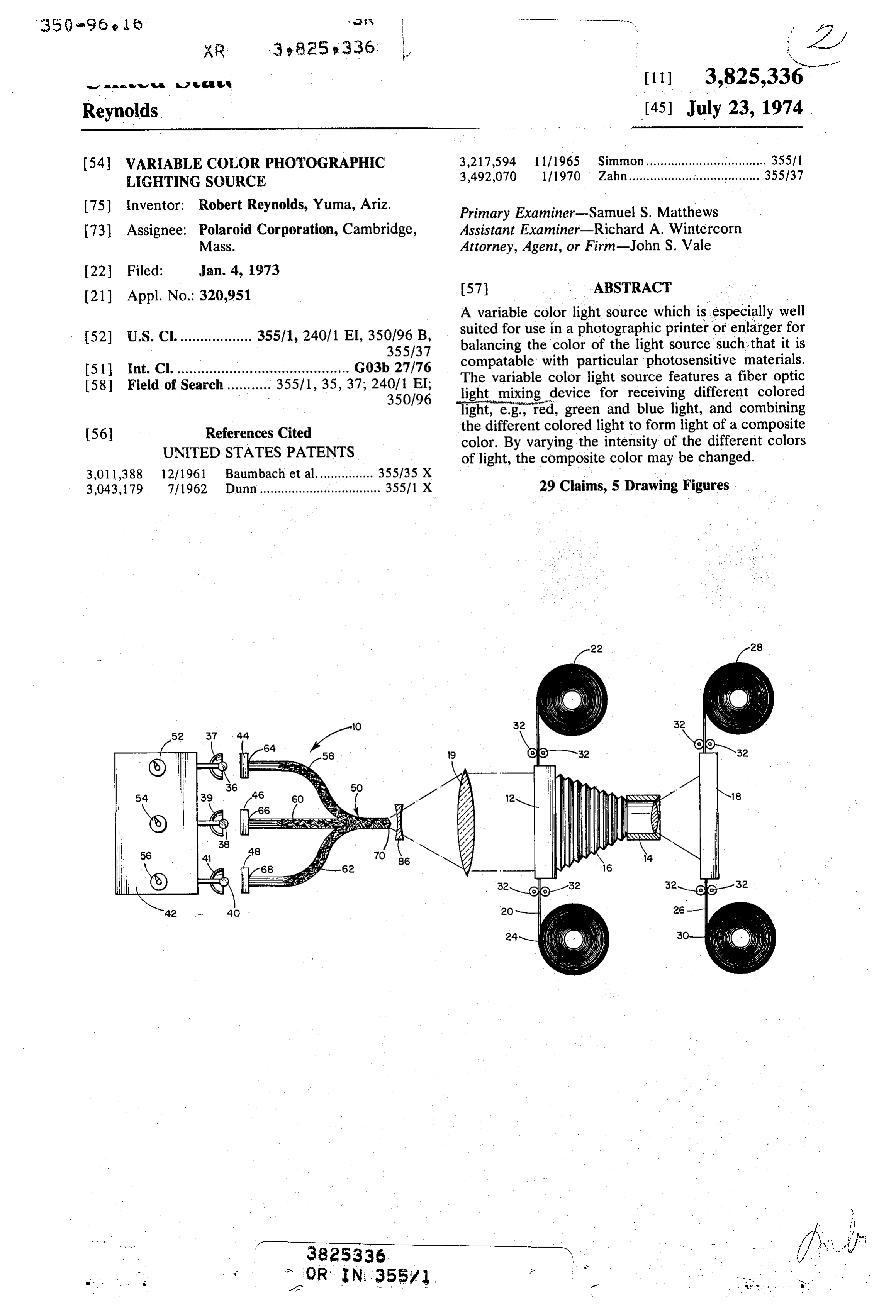
as a uvva was au/VCA (11) 3,825,336 Reynolds (45) July 23, 1974 54) VARIABLE COLOR PHOTOGRAPHIC 3,217,594 11/1965 Simmon. 355/1 LGHTING SOURCE 3,492,070 1 / 1970 Zahn......... wu a was 8 355/37
75) Inventor: Robert Reynolds, Yuma, Ariz. Primary Examiner-Samuel S. Matthews 73) Assignee: Polaroid Corporation, Cambridge, Assistant Examiner-Richard A. Wintercorn Mass. Attorney, Agent, or Firm-John S. Vale
21 Appl. No.: 320,951 57 ABSTRACT A variable color light source which is especially well
OO AW a 4. suited for use in a photographic printer or enlarger for 52 U.S. Cl 355/1, 240/1 EI, 359 balancing the color of the light source such that it is 51 Int. Cl. G03b 27/76 compatable with particular photosensitive materials.
light variable mixing color devicelight for source features receiving a fibercolored different optic light, e.g., red, green and blue light, and combining 56 References Cited the different colored light to form light of a composite color. By varying the intensity of the different colors
UNITED STATES PATENTS of light, the composite color may be changed. 3,011,388 12/1961 Baumbach et al................ 355/35 X . 3,043,179 7/1962 Dunn.................................. 355/1 x 29 Claims, 5 Drawing Figures
Page 2
Drawing sheet — no readable text.
Page 3
Drawing sheet — no readable text.
Page 4
WARIABLE COLOR PHOTOGRAPHIC LIGHTIN apparently employs multiple reflections within a glass SOURCE or transparent plastic cylinder.
Each of the above-mentioned mixing devices is a rel
BACKGROUND OF THE INVENTION atively low efficiency light transmitter. In order to pro 1. Field of the Invention vide adequate light levels at the negative for shortex The present invention relates to the field of photogra the inputtimes, posure high wattage lamps must be employed at phy and, more particularly, to a variable color light excessive heat tothebemixing end of devices. This in turn causes generated within the lighting sys source for use in photographic enlargers or printers. tem. The heat problem either limits the size of the 2. Description of the Prior Art 10 lamps that can be used, thereby extending exposure Reproducing color photographs on a commercial time, or requires that complex heat reducing or cooling basis generally involves the use of high-speed auto aids be built into the system. mated printers. In one system, where the copies are to be made from a positive print, individual prints are SUMMARY OF THE INVENTION photographed with a copy camera employing a large 15 The present invention provides a variable color light roll of film. The roll of film is developed to produce source for use with a photographic printer or enlarger. color internegatives.
The roll of internegatives is loaded into an enlarging In a preferred embodiment, the light source com printer which also holds a roll of suitable color printing prises individual sources of red, green, and blue light; paper. 20 means for individually varying the intensity of these The internegatives are sequentially advanced to a three primary color light sources; and a unique, highly printing station where they are illuminated and pro efficient, fiber optic light-mixing device for additively jected onto the roll of advancable printing paper. Once mixing various the printing phase is complete, the roll of printing to produce lightintensities
composite green, and blue light paper is developed to produce positive prints. 25
The mixing devices comprise first, second and third
It is well known in the photographic art that color incoherent ...--war-wrwr. rew'st wer
bundlesofindividual optic fibers, each bun film and positive print paper may vary from batch to dle having an input end and an output end. batch in terms of color balance. Therefore, it is a com mon practice to test the film and paper combination for is The input end of each of the three fiber optic bundles "color balance before printing. Based on the test results, light sources.coupled 30 optically
The to one of the three primary color output ends of the three bundles are the color of the light source in the printer or enlarger joined together by interweaving the individual optic fi is adjusted to compensate for any imbalance.
One method used to adjust the color of a "white" output end of the mixing device. a common composite bers forming the bundles to form light source is to place one or more subtractive yellow, The individual fibers are arranged in a systematic cyan, and magenta filters between the light source and 35 manner, alternating fibers from each of the three bun the negative. Major disadvantages of such a system are dles, to form that the filters are costly, short-lived, and being incre put end of thea device.
mosaic or reseau at the composite out mental only permit step adjustments in color. Looking at the composite output end, one sees a geo An alternative method for color balancing a light 40 metric source is the additive system wherein individual of threearray of individual fiber ends clustered in groups transmitting red, green, and blue light. As the sources of red, green, and blue light are combined or light is transmitted beyond the ends of the fibers in ex additively mixed to produce "white' light. One advan panding and overlapping cones, the primary colors mix tage of this system is that the color of the composite to form a composite additive color. light may be continuously varied over a wide range of 45 When the intensity of all three of the primary color colors by varying the amounts of the three primary col sources ors being used to illuminate the negative. For example, changingisthe the same, the composite light is "white." By relative intensities of the lamps, the com the intensity of each of the three sources may be ad posite color may be changed. justed to vary the composite color. This unique system retains the favorable characteris On the other hand, the adjustment may be made on 50 tic of providing continuous color changes rather than a time base. The red light source may operate for a rel atively short time during exposure while the green and step-wise backs of alterations, yet it does not suffer the draw the prior art systems.
blue sources operate for a longer time period. An ex ample of an additive light source system utilizing the the fiber opticthebundles,
Because of high light transmission efficiency of the light levels needed at the time base method may be found in U.S. Pat. No. 55 input end of the light-mixing device are relatively low.
A major problem associated with the prior art addi The use of incoherent fiber optic bundles provides tive light systems is its lack of efficiency in terms of another advantage. Because the light from the red, light utilization. Generally, the inefficiency occurs at green, and the point where the three primary colors are mixed or 60 transmitted blue combined.
light sources is "scrambled' as it is along the bundles, irregularities or "hot spots” in the incandescent lamp filaments of the pri
Some systems use a frosted glass plate as a diffuser mary coupled with other reflective devices to mix the red, positecolor light sources are not discernible at the com output end of the device. This provides more green, and blue light. Other systems employ an inte uniform grating sphere or dome for combining the light by mul 65 tive. illumination over the entire area of the nega tiple internal reflections. In the previously cited U.S. Also, because the fiber optic bundles may be flexed, Pat. No. 3,120,782, reference is made to a "light inte bent, or twisted without disturbing the performance of grating bar" for combining the three primary colors. It the device, the input ends of the bundles and the red,
Page 5
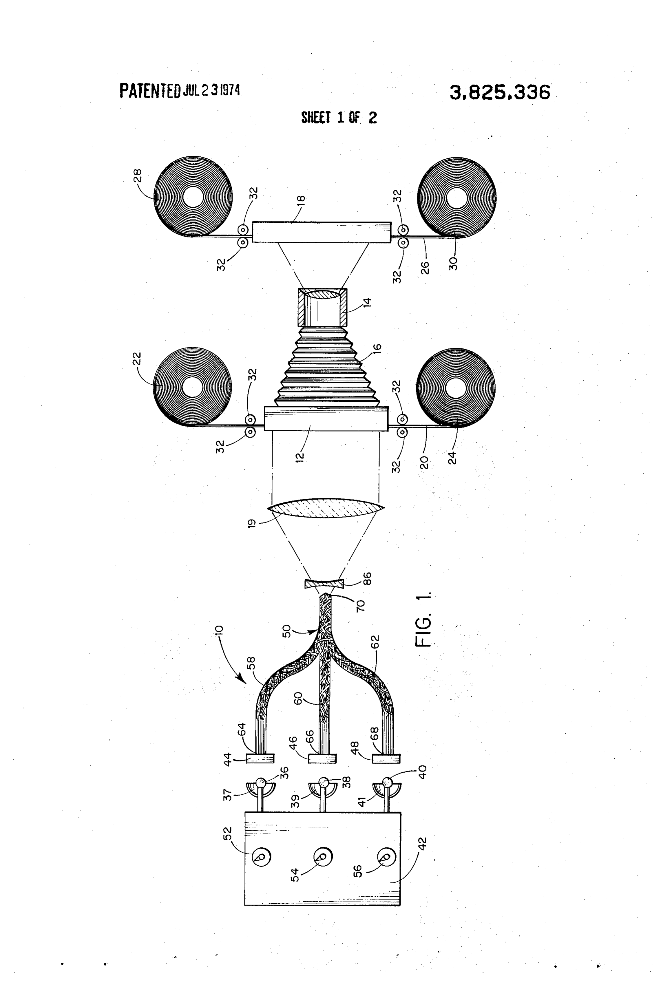
green, and blue light sources need not be located in light source 10 in operative relation with the essential alignment with the composite output end of the mixing elements of a typical commercial color enlarging device. This allows the designer considerable latitude printer.
in positioning the three primary light sources within the The printer comprises a negative or film support printer or enlarger, member 12, an enlarging or projection lens 14 coupled While the mixing device is primarily described as to support member 12 by an expandable bellows 16; a being configured for combining light from three inde positive print paper support 18 and a condensing lens pendent light sources, alternate embodiments are dis 19 positioned behind the negative support 12. closed for mixing light from two, four or even more in The color negatives or internegatives to be repro dependent light sources. 10 duced are supplied in a long roll of film 20 coupled be Therefore, it is an object of the present invention to tween a supply reel 22 and a take-up reel 24 disposed provide a simple, easy to use, inexpensive, and highly on opposite sides of the film support member 12. The efficient variable color additive light source for use print paper 26 is also supplied in a long roll that is cou with a photographic enlarger or printer. pled between a supply reel 28 and a take-up reel 30 dis It is another object of the invention to provide such 5 posed on opposite sides of the print paper support 18. a variable color light source which includes two or more different colored light sources, means for inde The film or color negative material 20 and the print pendently varying the intensity of such light sources, paper 26 are adapted to be intermittently advanced and means including a fiber optic mixing device for ad within their respective support members 12 and 18 by ditively combining the light from the two or more 20 suitable indexing drive means (not shown) connected sources to produce light of a composite color. to their respective supply and take-up reels 22, 24, 28 It is another object of the present invention to pro and 30. It will be noted that film 20 and paper 26 may vide a fiber optic mixing device comprising a plurality be properly aligned with their respective support mem of incoherent bundles of optic fibers, each of the bun 25 bers by employing guide rollers 32 at the entrance and dles having an input end and an output end and being exit ends of support members 12 and 18. In some types formed by a plurality of randomly interwoven optic fi of printers, the rollers 32 may be rotatably driven to
bers, said input end of each bundle being optically cou provide at least a portion of the transport function. pled to a light source of a different color and the output With a color negative or transparency supported in ends of all of said bundles being interwoven in a sys 30 member 12 in alignment projection lens 14, light from tematic manner to form a composite common output source 10 is directed through condensing lens 19 to il end for additively combining the different colored luminate the negative. An image of the illuminated neg lights as they are transmitted from the composite out ative is projected by lens 14 on the positive print paper put end. or photosensitive method 26 to form a latent image It is yet another object of the present invention to therein during an appropriate exposure interval. If a provide a photographic enlarger or printer which in 35 second copy is to be made, the print paper 26 is in cludes a variable color light source formed in part by dexed one frame and the exposure sequence is re a fiber optic light-mixing device. peated. After an appropriate number of exposures have Other objects of the invention will in part be obvious been made, both the film 20 and the paper 26 are in and will in part appear hereinafter. 40 dexed one frame to begin making positive prints of the BRIEF DESCRIPTION OF THE DRAWINGS next negative on the roll.
After the roll of print paper has been exposed, it is
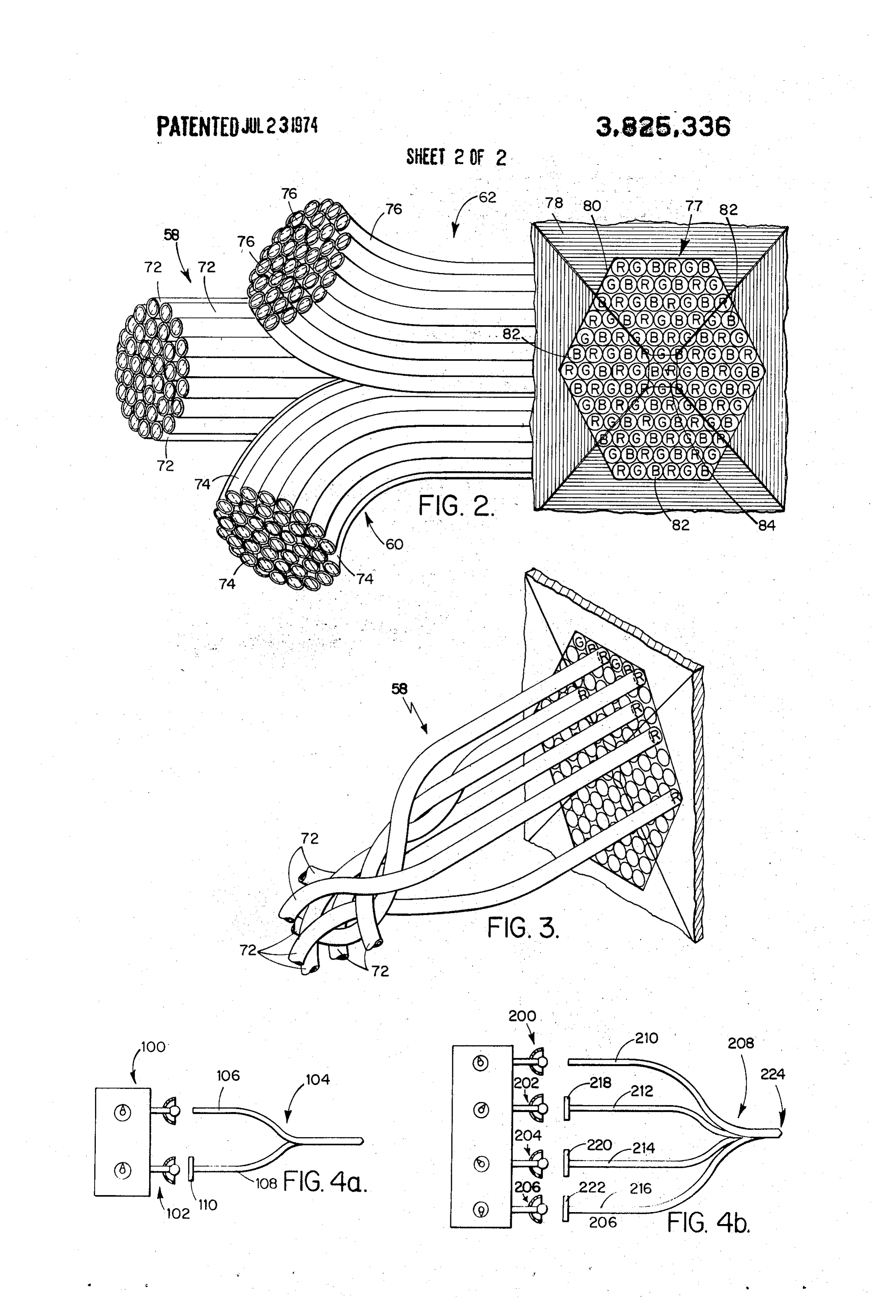
For a fuller understanding of the nature and objects transferred to an appropriate apparatus for processing. of the invention, reference should be had to the follow ing detailed description taken in connection with the 45 The above brief description of the enlarging printer accompanying drawings wherein: is provided to illustrate a typical operating environment FIG. 1 is a diagrammatic representation of a photo for the light source 10. It will be understood that the graphic enlarger or printer showing a variable color scope of the present invention goes beyond the bounds light source embodying the instant invention in opera of the described printer and that the light source 10 tive relation with the optical system of the enlarger or 50 may be used with other types of photographic enlargers printer, said variable color source comprising red, (including the type accepting only one negative at a green, and blue light sources, a power supply for inde time) and photographic printing apparatus. pendently varying the intensity of each of the three As noted earlier, a color print produced by projecting sources, and a fiber optic light-mixing device; an image of the color negative onto the positive print FIG. 2 is a perspective view of a composite output paper with a "white' light source may not be color bal end of the fiber optic mixing device showing the sys 55 anced due to some color imbalance in the negative, or tematic arrangement of the interwoven optic fibers positive paper, or both. Other sources of color varia from three incoherent bundles of fibers forming the tion may be attributed to the color of the light source mixing device; used when the negative was exposed in the camera, the FIG. 3 is a perspective view of the composite output 60 type of processing chemicals used, etc. end of the mixing device showing the incoherent nature In any event, a test print will generally indicate that of one of the three fiber optic bundles; and some adjustment in the color of the enlarger's light FIGS. 4a and b are diagrammatic representations of source is necessary to produce a better balanced posi alternative embodiments of the instant invention. tive print.
DESCRIPTION OF THE PREFERRED 65 For example, if the positive print has an overall yel EMBODIMENT low cast, then the blue-sensitive layer of the positive print paper, which is responsible for formation of yel
FIG. 1 shows, in diagrammatic form, a variable color low dye in the print is receiving too much blue light.
Page 6
S 6
The print may be color balanced by reducing the The fiber optic mixing device comprises three sepa amount of blue light in the light source illuminating the rate incoherent bundles 58, 60, and 62 of optic fibers. negative. The input end 64 of bundle 58 is optically coupled to In subtractive processes, blue light is suppressed or the source of red light to receive its light output and absorbed by placing a yellow filter in front of the transmit the output along its length in an incoherent “white' light source. manner with a minimum of light loss. Similarly, the In additive light source systems, where the "white' input end 66 of bundle 60 and the input end 68 of bun light is generated by additively mixing red, green, and dle 62 are optically coupled to the green and blue light blue light, the color balance is restored by reducing the SOURCES.
intensity of the blue light source, or increasing the red O The opposite ends, or output ends, of the fiber optic and green, thereby providing a composite color having bundles are joined together (or more precisely interwo a reduced blue content. ven in a manner to be described hereinafter) to form The amount of enlarger light source correction is de a composite output end 70 of light-mixing device 10. termined by various test methods such as densitometer 15 Each of the incoherent bundles 58, 60, and 62 is readings to step wedge tests. Such test methods are well formed by a plurality of individual, flexible, light trans known to those having ordinary skill in the art of mak mitting, optic fibers, each of which has an input end ing color prints and, therefore, they will not be dis and an output end.
cussed further within the instant disclosure. Each of the flexible fibers is formed by an inner core A variable color light source 10 embodying the in 20 having a first index of refraction and an outer sheath, stant invention comprises: three tungsten lamps 36,38, covering the core, having a second index of refraction and 40, each having its own parabolic focusing reflec which is lower than the first index of refraction. The in tor (37,39, and 41, respectively) associated therewith; terface between the sheath and core provides an envi a three channel power supply 42 connected to the ronment for highly efficient light transmission along the length of the fiber by multiple internal reflections.
lamps 36, 38, and 40 for individually powering and 25 Since varying the intensity of each of the lamps 36, 38, and the light is substantially totally internally re 40; red, green, and blue filters 44, 46, and 48 posi flected, loss.
the fiber may be bent or curved without light tioned in front of lamps 36, 38, and 40, respectively;
and a fiber optic light-mixing device 50 optically cou The fibers may be made of coated glass or coated pled to the three primary colored filters 44, 46, and 48. 30 plastic. The glass fibers are more suitable for high tem perature applications but are less flexible than the plas
In a preferred embodiment, the power supply 42 is of tic be fibers. Experience has shown that plastic fibers may used in the mixing device 10.
the constant voltage type to counteract any fluctua tions in the line voltage feeding it. It is divided into nature.three
The bundles 58, 60, and 62 are incoherent in three separate channels for independently powering 35 of individualisfibers
That to say that they are formed by a plurality that are interwoven along their each of the three lamps 36, 38, and 40. Each power length in a random manner to form the bundle. channel is provided with a control member, for varying This is in contrast to a coherent bundle where the fi the power input to each of the lamps, preferably by bers are laid up in systematic parallel fashion so that an varying the voltage input thereto. In FIG. 1, the individ end of an individual fiber at the input end of the bundle ual control members are represented as knobs or dials. 40 occupies the same relative position to the fiber ends Knob 52 regulates the voltage input to lamp 38, and around it at the output end. Coherent fiber bundles are knobs 54 and 56 are used to control lamps 38 and 40, used for image transmission applications wherein it is respectively.
The red filter 44 positioned in front lamp 36 and re 45 the inputtoendmaintain desirous the coherency of the image from of the fiber bundle to its output end.
flector 37 transmits red light and absorbs the other col In the instant application, the input ends of the fiber ors in the spectrum emitted from the tungsten lamp 36. optic bundles 58,60, and 62"look at' the glowing fila Thus filter 44, lamp 36, reflector 37, and a portion of ments of lamps 36, 38, and 40 through the filters 44, power supply 42 may be considered to be a "source of 46, and 48.
red light" for the purposes of this disclosure. Knob 52 Lamp filaments tend to develop "hotspots" with age. is representative of a portion of the power supply that 50 That is, the light output tends to become non-uniform is used to regulate or vary the intensity of the "source along the length of the filament. If coherent fiber optic of red light' by changing the power input or voltage to bundles were employed, the non-uniform light output lamp 36. This same definition applies to the other would be transmitted along the light-mixing device and lamps, filters, and control knobs. Thus the light source 55 illuminate the negative at negative support 12 in an un 10 is to be considered as including a source of red light, We are.
a source of green light, a source of blue light, and By employing incoherent bundles of fiber optics, the means connected to these sources of colored light for image of the filament is scrambled as it is transmitted independently varying their respective intensities. along each bundle and therefore the light output from The light outputs of the red, green, and blue sources 60 the end of the bundle is more even in its distribution. are fed into the input end of the fiber optic mixing de A cluster of fibers at the imput end of the bundle "see vice 50 and are additively mixed as they emerge from ing' a hot spot will not be clustered at the output end the output end to form light of a composite color. thereby redistributing portions of the hot spot or dis When the red, green, and blue light outputs are of sub pensing it at the output end of the bundle. stantially equal strength, the composite color is 65 While the individual fiber forming the incoherent “white." One may think in terms of "white' light as bundles 58, 60 and 62 are randomly interwoven within being a balanced light with no one primary color being each bundle, they are interwoven together at their re dominant, spective output end to form the composite output end
Page 7
50 in a systematic manner to provide an ordered distri Fiber optic mixing devices employing three coherent bution of fibers carrying red, green, and blue light. bundles of optic fibers systematically interwoven at Referring now to FIGS. 1 and 2 of the drawings, the their output ends have been used to transmit and inte three incoherent bundles 58, 60, and 62 are joined or grate red, blue, and green images in a television system. interwoven together at their respective output ends to Examples of such mixing devices may be found in U.S. form the composite output end 70 of mixing device 50. Pat. Nos. 3,043,179 and 3,130,263. For the sake of clarity, the individual optic fibers form The mixing device 50 of the instant invention em ing bundle 58 will be designated as fibers 72. The optic ploys incoherent bundles rather than coherent bundles fibers in bundles 60 and 62 will be designated 74 and to scramble the information being transmitted rather 76. O than faithfully reproduce it at the output end. The individual fibers of the three bundles are ar As noted earlier, the mixing of the red, green, and ranged in a systematic order to form a mosaic or reseau blue light does not occur within mixing device 50 but 77 at composite output end 70. In a preferred embodi rather at a point slightly beyond the composite output ment, the reseau 77 is hexagonal in cross section, but end 70. The red, green, and blue light emerges from the it may take other shapes, e.g., a circle, square, triangle, 15 output ends of their respective individual fibers 72, 74, rectangle, or other shape as may be desired or needed. 76 and propagates therefrom in expanding cones of In the illustrated embodiment, a metal or plastic collar light radiating outwardly about a longitudinal transmis 78, having a hexagonal opening 80 therein, is used to sion axis of device 50. Because of the close pack den facilitate the laying up of the systematic reseau and for sity of the fibers, the adjacent red, green, and blue holding the fibers in a close packed relationship. 20 cones of light overlap at a very short distance from Starting at the upper left-hand corner of the reseau composite output end 70 thereby additively mixing to 77, a first row of fibers is established by alternating fi form light of a composite color. bers from each of the three fiber optic bundles. The The composite color light also propagates from the first row of the reseau 77 begins with a fiber 72. It is fol 25 output end 70 in an expanding cone of light. Assume lowed with a fiber 74 which is followed by a fiber 76. for the moment that the output ends of the individual This same pattern is repeated to complete the first row. fibers 72, 74, and 76 forming the reseau 77 terminate in a common plane so that the output end 70 of mixing
The second row of the reseau 77 is substantially par device 50 is substantially flat. The cone of composite allel to the first row, but because of the circular cross light subtends a solid angle which is mainly a function section of the ends of the individual fibers 72, 74, and 30 of the diameters of the individual fibers 72,74, and 76. 76, the fibers of the second row are interdigitated with Fine diameter fibers will generate a relatively small respect to the fibers of the first row to achieve maxi solid angle while coarser fibers will generate a larger mum packing density. From left to right the sequence solid angle. By increasing the number of fibers 72, 74, of fibers is 74,76, 7274, 76, 72, 74. The third row is and 76 forming the reseau, the solid angle is increased substantially parallel to the first and second rows and 35 slightly, but for the most part it is defined by fiber size, its fibers are in turn interdigitated with those of the sec not number. The number of individual fibers in the re ond row. The fiber sequence of the third row, from left seau (assuming that they all transmit substantially the to right, is 76, 72, 74,76, 72, 74,76, 72. The next 10 same amount of light) will determine the intensity of rows of the reseau 77 are formed by repeating the pat 40 the composite light at any given distance from the com tern established in the first three rows. posite output end 70.
For the ease of illustration, the output ends of the in In some instances, the cone of light emanating from dividual fibers 72, 74, and 76 carry the designation R, the composite output end 70 of a mixing device 50 hav G, and B, respectively, to indicate that fibers 72 carry ing a planar reseau 77 may be too small to completely red light to the end of the reseau while fibers 74 and 76 45 fill the condensing lens 19 of the printer or enlarger. carry green and blue light, respectively. One solution to this problem is to shape the compos It will be noted that the reseau is made up of a repeat ite output end 70 such that it disperses or bends the ing pattern of triangular clusters of fibers, each of light rays transmitted therefrom outwardly from the which includes red, green, and blue light transmitting longitudinal transmission axis. As best shown in FIG. 2, fibers 72,74, and 76. For example, one triangular clus 50 the composite output end is suitably ground and pol ter is formed by the first fiber 72 in the first row and the ished such that it includes four substantially triangular first and second fibers, 74 and 76, in the second row. shaped facets 82. The reseau rather than being dis Another triangular cluster is formed by the first two fi posed in a single plane that intersects the longitudinal bers, 72 and 74, in the first row and the second fiber 76 transmission axis of the combined bundles 58, 60, and in the second row. A substantially equal number offi 62, now exhibits a pyramidal shape, having its apex 84 bers 72, 74, and 76 are used to form the reseau 77 and 55 at the leading edge of end 70, with all but a few individ they are envenly distributed with the resau 77. ual fibers at the center, being disposed on one of the FIG. 3 shows a rear view of the reseau 77 and repre four inclined facets 82.
sentative fibers 72 of incoherent bundle 58 only. This The number of facets and their angle relative to the is to illustrate the incoherent nature of bundle 58. It 60 output transmission axis may be varied depending on will be noted that the individual fibers 72 are randomly the degree of dispersion required. Optically, each of interwoven along their length before they reach the re the facets acts as a prisim mounted on the end of the seau 77. As noted previously, this type of bundle struc combined fiber optic bundle and provides, by its shape, ture prevents a coherent image of the filament of lamp the means for bending the light rays emerging from the 36 from being transmitted to the output end 70 which 65 composite output end 70 to increase the solid angle may lead to an uneven distribution of red light at the subtended by the cone of composite color light. reseau thereby causing uneven illumination of the neg Another method for increasing the solid angle or ative supported by the support member 12. "field of illumination' is to employ an appropriate neg
Page 8
ative dispersing lens 86 between the reseau 77 and the ored by the filter pack 110. This type of structure gives condensing lens 19. As shown in FIG. 1, even greater the operator much more flexibility and finer control in dispersion may be achieved by combining both meth balancing the color of his light source than he would ods. The faceted output end 70 of the mixing device 50 have if he were using the subtractive filters alone. directs the composite light output to a negative lens 86 Another application relates to black-and-white print positioned in alignment therewith which in turn further ing using variable contrast filters. By mixing the expands the "field of illumination' to completely fill “white" light of source 100 with the light of source 102 the condensing lens 19. colored by one or more variable contrast filters 110, In operation, the combination of a particular roll of the operator may compensate for light losses due to the negative material 20 and a particular roll of positive O filters by increasing the intensity of the composite light print paper 26 is tested for color balance. If no imbal output to shorten exposure time.
ance is found, the intensities of lamps 36, 38, and 40 FIG. 4b diagrammatically illustrates another alterna are adjusted so that substantially the same amounts of tive embodiment employing four light sources 200, red, green, and blue light are transmitting into the input 202, 204, and 206, in combination with a fiber optic ends 64, 66, and 68, respectively, the three incoherent 15 mixing device 208 formed by four incoherent fiber bundles of the optic fibers 58,60 and 62. The light trav optic bundles 210, 212, 214, and 216. As in the previ els along the individual fibers 72, 74, and 76 forming ously described embodiment, the intensity of each of the three bundles 58,60, and 62 and emerges from the the four light sources may be varied independently of reseau 77 at the composite output end 70. Upon leav one another. Light source 200 provides "white" light. ing the output end 70, the red, green, and blue light ad 20 Sources 202,204, and 206 provide red, green, and blue ditively combine to form "white" light. Being further light, respectively, by positioning appropriate colored dispensed by the negative lens 86, the white light fills filters 218, 220, and 220 between their lamps and the the condensing lens 19 which in turn directs it to the input ends of their respective fiber optic bundles 212, negative support 12 to illuminate a colored negative 214, and 216.
supported thereon. An image of the illuminated nega 25 The composite output end 224 of the fiber optic mix tive is then projected onto print paper 26 on support ing device 208 is formed by systematically interweaving member 18 by lens 14 to form a latent image therein. the individual fibers of the four incoherent bundles. The fibers are arranged to form a reseau or mosaic hav
If the test indicates an imbalance in the combination ing a repeating pattern of clusters of four fibers, each of negative and positive material, the color of the com 30 cluster including fibers for transmitting "white", red, posite light is adjusted by varying the intensity of one green, and blue light. v or more of the lamps 36, 38, and 40. For example, if By adding a fourth light source and fourth incoherent positive test print is too yellow, the voltage input to bundle to the mixing device, the total light output of lamp 40 is reduced to decrease the amount of blue light the mixing device, at the composite output end 224, is being fed into the mixing device 50 through incoherent 35 increased thereby permitting shorter exposure times. bundle 62. In order to maintain the intensity of com One skilled in the art will appreciate that many other posite color light output at some predetermined value, embodiments of the additive light source may be con a reduction of power input to lamp 40 will require cor structed to suit particular applications. For example, a responding power increases to lamps 36 and 38. Alter larger number of lamps, filters, and incoherent bundles natively, increasing the power to lamps 36 and 38 may 40 may be employed. This type of structure allows the in be dispensed with if the exposure interval is increased dividual lamps to be of the low wattage type rather than to compensate for the decreased intensity of the light using fewer high wattage lamps.
emanating from the output end 70 of the mixing device Regardless of the number of lamps and incoherent 50. bundles, or the number of fibers forming each bundle Up to this point the invention has been illustrated by 45 (i.e., one bundle forming part of a mixing device may a color variable light source having three light sources contain fewer or more individual fibers than another whose intensities may be varied independently, in com bundle) in any given mixing device, the basic principles bination with a fiber optic light-mixing device formed are still the same. The additive light source will include by three incoherent bundles of optic fibers having input 50 two or more light sources of at least two different col ends for receiving the light output of the three sources ors, means for independently varying the intensities of and a common systematically interwoven output end each of the light sources, and a fiber optic mixing de for integrating the light output of the three sources in vice comprising a plurality of incoherent bundles of an additive manner. optic fibers, one for each light source, interwoven at It will be understood that the same basic principles 55 their output ends to establish a systematic array of fi disclosed above may be applied to other types of light bers such that the different color lights are intermixed sources. For example, FIG. 4a shows a color variable to form a composite color light at a point slightly be light source formed by two light sources 100 and 102 yond the output end of the fiber optic mixing device. in combination with a fiber optic light-mixing device Since certain changes may be made in the above ap 104 formed by two incoherent bundles 106 and 108 of 60 paratus without departing from the scope of the inven optic fibers interwoven in the manner described previ tion herein involved, it is intended that all matter con ously. One application for this type of structure is to ad tained in the above description or shown in the accom ditively mix "white"light from source 100 with colored panying drawings shall be interpreted as illustrative and light from source 102, provided by inserting a pack 110 not in a limiting sense.
of subtractive color filters (yellow, cyan, and magenta) 65 What is claimed is:
between the lamp of source 102 and the input end of 1. A variable color light source for illuminating nega incoherent bundle 108. In this manner the composite tives in a photographic printer, said variable color light color output is a mixture of "white" light and light col source comprising:
Page 9
means for receiving a plurality of individual light 6. A variable color light source as defined in claim 1 sources, each providing light of a different color; wherein each of said individual optic fibers includes an means for independently varying the intensity of said inner core having a first index of refraction and an different colored light provided by each of said plu outer sheath, covering said core, having a second index rality of light sources; and of refraction which is lower than said first index of re means for receiving said different colored light from fraction.
each of said plurality of light sources and for com 7. A variable color light source as defined in claim 1 bining said different colored light to provide light wherein said plurality of individual light sources in for a composite color representing an additive mix cludes at least a source of red light, a source of green ture of independent intensities of said different col O light, a source of blue light, and a source of white light. ored light;
said receiving and combining means including a plu 8. A variable color light source as defined in claim 1 rality of bundles of individual light transmitting where optic fibers, the number of said bundles being includeseach an of said plurality of individual light sources electrically powered lamp and said means equal to the number of said light sources, each of 15 connected to each of said plurality of individual light said plurality of bundles having an input end and an sources includes means for independently varying the output end, said input ends of each of said plurality power input to each of said lamps.
of bundles being optically coupled, respectively, to 9. A variable color light source as defined in claim 8 one of said plurality of light sources for receiving wherein said means for independently varying the said light of different colors for transmission 20 power input to each of said lamps includes means for through said plurality of bundles to their respective varying the voltage input to each of said lamps. ends, 10. A variable color light source as defined in claim said output ends of said plurality of bundles being in 8 wherein each of said plurality of independent light tegrated with one another to form a composite out sources includes a filter for transmitting light of a dif put end of said receiving and combining means, 25 ferent color, said filters being positioned between said said individual optic fibers of said plurality of bun dles being interwoven to form a systematically or lamps and the input end of said bundle associated with each lamp.
dered array of fibers, selected alternatively from 11. A variable color light source for illuminating neg said composite output end to form light of a sub atives in a photographic printer, said variable color stantially composite color for illuminating the neg 30 light source comprising:
atives, said individual fibers of each of said plural means for receiving sources of red, green, and blue ity of bundles being randomly arranged such that light;
light received at their respective input ends is trans means for independently varying the intensity of said mitted to said ordered array at said composite out 35 red, green, and blue light; and put end in an incoherent manner. means for receiving and combining said red, green, 2. A variable color light source as defined in claim 1 and blue light to produce light of a composite color wherein said plurality of individual light sources in representing an additive mixture of said indepen cludes a source of red light, a source of green light, and a source of blue light and said receiving and combining 40 dent intensities of said red, said green, and said blue light;
means include first, second, and third bundles of optic said receiving and combining means including first, fibers having their respective input ends optically cou second, and third bundles of individual light trans pled, respectively, to said sources of red, green, and mitting optic fibers, each of said bundles having an blue light. input end and an output end, said input ends of said 3. A variable color light source as defined in claim 1 first, second, and third bundles being optically cou wherein said individual fibers of said plurality of bun 45 pled, respectively, to said sources of red, green, dles are systematically arranged at said composite out and blue light for receiving said red, said green, and put end of said receiving and combining means in sub said blue light for transmission through said first, stantially parallel, adjacent, interdigitated rows, each of said rows having a repeating sequence offibers selected 50 put ends,and third bundles to their respective out second, alternatively from said individual fibers of said plurality said output ends of said first, second, and third bun of bundles, and said adjacent rows being configured to dles being systematically interwoven to form an or provide a repeating array of clusters of fibers at said dered array of fibers, selected alternatively from composite output end, each of said clusters including said first, second and third bundles, such that said one fiber from each of said plurality of bundles. red, green, and blue light intermixes when trans 4. A variable color light source as defined in claim 1 55 mitted from said composite output end to form wherein said light receiving and combining means in light of a composite color for illuminating the nega cludes a longitudinal light transmission axis and said or tives, said individual fibers of each of said first, sec dered array of fibers at said composite output end is ond, and third bundles being randomly arranged configured to include a plurality of surfaces which are 60 therein such that light received at their respective inclined with respect to said light transmission axis for input ends is transmitted to said ordered array at directing light of a composite color outwardly from said said composite output end in an incoherent man light transmission axis. er.
5. A variable color light source as defined in claim 1 wherein said plurality of independent light sources in 65 1112.wherein
A variable color light source as defined in claim said individual fibers of said first, second cludes at least a first light source providing light of one and third bundles are systematically arranged at said color and a second light source providing light of a composite output end of said receiving and combining color different from said one color. means in substantially parallel, adjacent, interdigitated
Page 10
rows, each of said rows having therein a repeating se one of the plurality of light sources for receiving quence of fibers selected alternatively from said indi the different colored light for transmission through vidual fibers of said first, second, and third bundles and said plurality of incoherent bundles to their respec said adjacent rows being configured to provide a re tive output ends;
peating array of clusters of fibers at said composite out 5 said output ends of said plurality of incoherent bun put end, each of said clusters including three fibers, one dles being integrated with one another to form a of each being selected from said individual fibers of composite output end of said fiber optic light mix said first, second, and third bundles. ing device by said individual optic fibers of said 13. A variable color light source as defined in claim plurality of incoherent bundles being systemati 11 wherein said receiving and combining means in O cally interwoven to form an ordered array of fibers, cludes a longitudinal light transmission axis and said or selected alternatively from each of said plurality of dered array at said composite output end is configured incoherent bundles, such that the light of different to include a plurality of surfaces which are inclined colors intermixes when transmitted from said com with respect to said light transmission axis for directing posite output end to form light of a composite light of a composite color outwardly from said light 15 color, said individual fibers of each of said plurality transmission axis. of incoherent bundles being randomly arranged 14. A variable color light source as defined in claim therein such that light received at the respective 11 when said sources of red, green, and blue light each input ends is transmitted to said ordered array at include a lamp associated therewith and an electrical said composite output end in an incoherent man power supply for supplying electrical power to each of 20 e.
said lamps and said means for independently varying 20. A fiber optic light-mixing device as defined in the intensity of each of said red, green, and blue light claim 19 wherein there are at least first and second sources includes means associated with said power sup light sources each providing light of a different color ply for independently varying the power input to each - and said light-mixing device includes a first incoherent of said lamps, 25 bundle of optic fibers having its input end optically . 15. A variable color light source as defined in claim coupled to the first light source and a second incoher 14 wherein said means for independently varying the ent bundle of optic fibers having its input end optically power input to each of said lamps includes means for coupled to the second light source.
varying the voltage input to each of said lamps. 21. A fiber optic light-mixing device as defined in 16. A variable color light source as defined in claim 30 claim 20 wherein a plurality of independent light 14 wherein said source of red light further includes a sources includes a source of red light, a source of green red light transmitting filter positioned between said light, and a source of blue light and said light-mixing lamp of said red light source and said input end of said device includes first, second and third incoherent bun first bundle of optic fibers and said green and blue light 35 dles of optic fibers having their respective input ends sources include, respectively, a green light transmitting optically coupled, respectively, to the sources of red, filter and a blue light transmitting filter positioned, re green, and blue light. : , spectively, between said lamp of said green light source 22. A fiber optic light-mixing device as defined in and said input end of said second bundle of optic fibers claim 19 wherein said individual fibers of said plurality and said lamp of said blue light source and said input 40 of incoherent bundles are systematically arranged at end of said third bundle of optic fibers. said composite output end of said light-mixing device 17. A variable color light source as defined in claim in parallel, adjacent, interdigitated rows, each of said 11 wherein each of said individual optic fibers includes rows having a repeating sequence of fibers selected al an inner core having a first index of refraction and an ternatively from said individual fibers of said plurality outer sheath, covering said inner core, having a second 45 of incoherent bundles, said adjacent rows being config index of refraction which is lower than said first index ured to provide a repeating array of clusters of fibers of refraction. at said composite output end, each of said clusters in 18. A variable color light source as defined in claim cluding one fiber from each of said plurality of incoher 11 wherein said composite output end of said receiving ent bundles.
and combining means is configured to have facets 50 23. A color mixing device as defined in claim 19 thereon for dispersing the light of a composite color. wherein said light-mixing device includes a longitudinal 19. A fiber optic light-mixing device for receiving light transmission axis and said ordered array at said light from a plurality of independent light sources, each composite output end is configured to include a plural of the light sources being configured to provide light of ity of surfaces which are inclined with respect to said a different color and also being configured to have the light transmission axis for directing light of a composite intensity of its light output varied independently from color outwardly from said light transmission axis. the light output of the other light sources, and for com 24. A fiber optic light-mixing device as defined in bining the different colored light to produce light of a claim 19 wherein said individual optic fibers include an composite color representing an additive mixture of inner core having a first index of refraction and an said independent intensities of the different colored 60 outer sheath, covering said inner core, having a second light, said fiber optic light-mixing device comprising: index of refraction which is lower than said first index a plurality of incoherent bundles of individual optic of refraction.
25. A photographic printer for exposing photosensi fibers, the number of said incoherent bundles being equal to the number of the plurality of light tive material to an image of an illuminated transpar sources, each of said incoherent bundles having an is ency, input end and an output end, said input ends of said photographic printer comprising:
means for supporting photosensitive material;
each of said plurality of incoherent bundles being means for supporting a transparency in alignment adapted to be optically coupled, respectively, to with the photosensitive material;
Page 11
a projection lens positioned between said photosensi tegrated with one another to form a composite out tive material and transparency support means for put end of said receiving and combining means by projecting an image of a transparency supported by systematically interweaving said individual optic said transparency support means onto the photo fibers of said plurality of bundles to form an or sensitive material supported by said photosensitive dered array of fibers, selected alternatively from material support means, and each of said plurality of bundles, such that said a variable color light source for illuminating the light of different colors intermixes when transmit transparency such that an image thereof may be ted from said composite output end to form light of projected onto the photosensitive material by said a composite color for illuminating the negative,
said color variable light source comprising; said individual fibers of each of said plurality of means for receiving a plurality of individual light bundles being randomly arranged therein such that sources, each providing light of a different color; light received at their respective input ends is trans means connected to each of said plurality of light mitted to said ordered array at said composite out sources for independently varying the intensity of 15 put end in an incoherent manner.
said different colored light provided by each of said 26. The photographic printer as defined in claim 25 plurality of light sources; and wherein said plurality of independent light sources in means for receiving said different colored light from cludes sources of red, green, and blue light and said each of said plurality of light sources and for com plurality of bundles of optic fibers includes first, sec bining said different colored light to produce light 20 ond, and third bundles having their respective input of a composite color representing an additive mix ends optically coupled, respectively, to said sources of ture of various intensities of said different colored red, green, and blue light.
light; 27. The printer of claim 25 further including at least said receiving and combining means including a plu one condensing lens positioned between said compos rality of bundles of individual light transmitting 25 ite output end and said means for supporting a nega optic fibers, the number of bundles being equal to tive.
the number of said plurality of independent light 28. A printer of claim 27 where said composite out sources, each of said bundles having an input end put end has facets thereon for dispersing the light of a and an output end, said input ends of each of said composite color such that it completely fills said con plurality of bundles being optically coupled, re 30 densing lens.
spectively, to one of said plurality of light sources 29. A printer of claim 27 further including a negative for receiving said light of different colors for trans lens between said composite output end and said at mission through said plurality of bundles to their least one condensing lens for further dispersing said respective output ends; light of a composite color.
said output ends of said plurality of bundles being in 35 ck k k :k sk
Provenance
- Collection
- Cited prior art
- Original PDF
- patentimages.storage.googleapis.com →
- Filed
- 1973-01-04
- Pages
- 11
- Method
- pdftotext (the PDF's own text layer) + pdftoppm 300dpi page scans
- Source
- Google Patents bibliographic record
- Granted
- 1974-07-23
- Inventors
- R Reynolds; Polaroid Corp
- Transcribed from
- patentimages.storage.googleapis.com →