patent · US3735174
Electric motor with hollow rotor and method of fabricating the hollow rotor
22 May 1973
Page 1 — bibliographic record
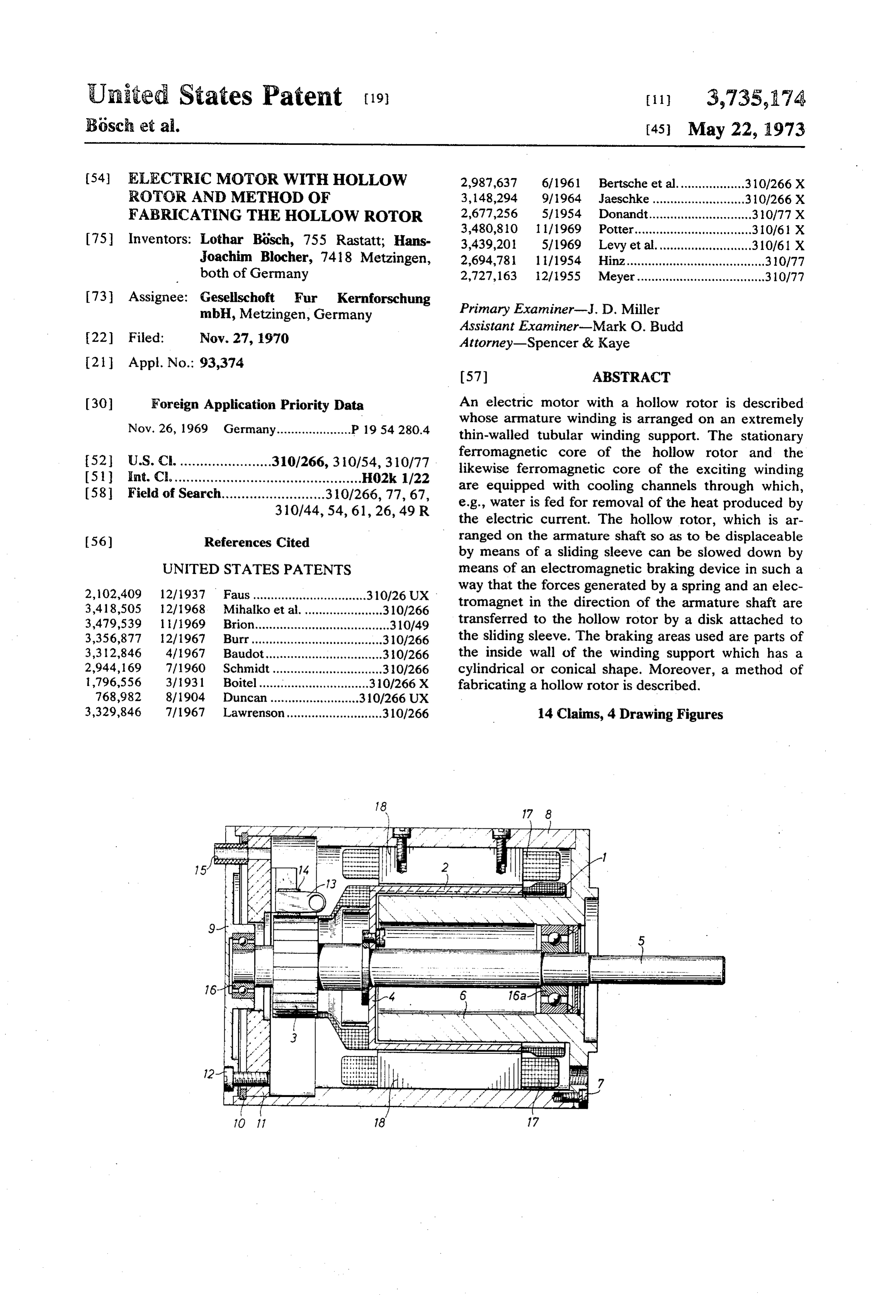
United States Patent (19) (11) 3,735,174 Bösch et al. (45) May 22, 1973 54 ELECTRIC MOTOR WITH HOLLOW 2,987,637 6/1961 Bertsche et al................... 310/266 X ROTOR AND METHOD OF 3,148,294 9/1964 Jaeschke........ ... .310/266 X FABRICATING THE HOLLOW ROTOR 2,677,256 5/1954 Donandt............................. 310/77 X 3,480,810 1 1/1969 Potter.................................310/61 X (75) Inventors: Lothar Bosch, 755 Rastatt; Hans 3,439,201 5/1969 Levy et al........................... 310/61 X Joachim Blocher, 7418 Metzingen, 2,694,781 ll/1954 Hinz....................................... 310/77 both of Germany 2,727, 163 12/1955 Meyer....................................310/77 73) Assignee: Gesellschoft Fur Kernforschung mbH, Metzingen, Germany Primary Examiner-J. D. Miller
Assistant Examiner-Mark O. Budd 22 Filed: Nov. 27, 1970 Attorney-Spencer & Kaye
(30) Foreign Application Priority Data An electric motor with a hollow rotor is described
whose armature winding is arranged on an extremely thin-walled tubular winding support. The stationary 52 U.S. C. .......................310/266,310/54, 310/77 ferromagnetic core of the hollow rotor and the I51) int. Cl. ............................................... H02k 1/22 likewise ferromagnetic core of the exciting winding 58 Field of Search.......................... 310/266, 77, 67, are equipped with cooling channels through which, 310/44, 54, 61, 26, 49 R e.g., water is fed for removal of the heat produced by the electric current. The hollow rotor, which is ar (56) References Cited ranged on the armature shaft so as to be displaceable by means of a sliding sleeve can be slowed down by
UNITED STATES PATENTS means of an electromagnetic braking device in such a 2,102,409 12/1937 Faus................................ 310/26 UX way that the forces generated by a spring and an elec 3,418,505 12/1968. Mihaiko et al....................... 310/266 tromagnet in the direction of the armature shaft are 3,479,539 l i? 1969 Brion......................................310/49 transferred to the hollow rotor by a disk attached to 3,356,877 12/1967 Burr...... ...310/266 the sliding sleeve. The braking areas used are parts of 3,312,846 4/1967 Baudot..... ...310/266 the inside wall of the winding support which has a 2,944,169 7/1960 Schmidt... ...30/266 cylindrical or conical shape. Moreover, a method of 1,796,556 3/1931 Boitel............................... 310/266 X fabricating a hollow rotor is described. 768,982 8/1904 Duncan....... ... .310/266 UX 3,329,846 7/1967 Lawrenson........................... 310/266 14 Claims, 4 Drawing Figures
Page 2
Drawing sheet — no readable text.
Page 3
Drawing sheet — no readable text.
Page 4
Drawing sheet — no readable text.
Page 5
Drawing sheet — no readable text.
Page 6
1 2:
ELECTRIC MOTOR WITH HOLLOW ROTOR AND If only one side of the winding support is connected METHOD OF FABRICATING THE HOLLOW to the shaft transmitting the torque, magnetic return ROTOR will be made in a well-known way through a free stand BACKGROUND OF THE INVENTION ing hollow cylindrical armature core extending into the hollow rotor and made of a material of high relative
The invention relates to a DC motor with hollow permeability with low eddy current losses. In the case rotor for the generation of high nominal torques and of smaller rotor diameters it may be useful to connect high accelerations at low moment of gyration. the winding support to the front side of a shaft butt and These motors are required especially for electrical fill the bore of the hollow rotor with a stationary cylin drives with extremely fast startup and slowing down ac O drical or hollow cylindrical armature core for magnetic tions, e.g., as servo-motors in measurement and control return.
systems where high efficiencies and minimum dimen The invention also serves purpose of attaining the sions are needed and, at the same time, only a low mo maximum possible current carrying capacity of the ar ment of inertia is to be overcome in the case of a sepa 15 mature winding and the exciting winding so that a pre rate drive. determined motor power is achieved with a minimum It is known (catalog "DC Mikromotoren" of Dr. of copper and, hence, low mass.
Faulhaber company, Feinmechanische Werkstatten, In the invention, this is achieved by an electric motor 7036 Schonaich/Wurtt., Germany) that these require consisting of a hollow rotor with a tubular winding sup ments can be fulfilled by keeping the weight of the ar port frictionally connected with the armature schaft, a mature low through separating the armature winding ferromagnetic armature core for magnetic return from the ferromagnetic armature carrying the magnetic which at least partly fills the bore of the hollow rotor flux. In this type of ironless hollow rotor the winding is and is firmly attached to the motor casing, and of de cast in a synthetic resin plastic or the like and con vices for removal of the heat produced by the electric nected with the armature shaft through a disk. 25. current from at least one of the components adjacent The fact that the winding treated with synthetic resin to the exciting and armature windings, the armature must itself be used to transmit the torque results in core of the hollow rotor and the ferromagnetic core of three specific disadvantages: The mechanical stability the exciting winding (exciting core). These devices of the assembly is limited, and influences of tempera may consist, e.g., of cooling channels arranged in the ture and mechanical oscillations may give rise to tem 30 armature core and the exciting core and through which porary or permanent deformations of the winding. This water is ducted as the coolant.
necessarily requires a wider air gap which, in turn, re In this case, it is advantageous to arrange bores on sults in either more expense for excitation or a decrease the periphery of the hollow cylindrical armature core of power. The temperature carrying capacity, which is extending in the direction of its longitudinal axis which limited for mechanical reasons, at the same time im 35 are divided into two groups of channels on the front plies a limit to the current carrying capacity and, side which is connected with the bearing plate, by one hence, to power. channel for introducing a coolant and extending mainly The same disadvantages are inherent in the ironless on the level of the front face, and another channel situ hollow rotor of another well-known motor which is de ated on the same level for removing a coolant, which scribed in the Honeywell catalog "Servomotor HSM" 40 two groups of channels are interconnected within each dated Nov., 1968. group and connected with each other by a third chan SUMMARY OF THE INVENTION nel on the other front side.
It may be advantageous for an exciting core with a
Hence, the invention is based on the problem of de cylindrical outside to have cooling channels arranged signing a motor with a hollow rotor whose winding does 45 on its periphery in the way of a thread with at least two not have to directly transmit the torque to the armature courses at a predetermined pitch in such a way that the shaft, in which deformations of the windings are impos coolant flows in through a first course and back in a sible and which allows small effective air gaps. second course. In this arrangement, the inlet for the In the invention, this problem is solved by an electric coolant is connected to a first course of the cooling motor consisting of an armature winding support which 50 channels on a front side of the exciting core and the is made of a material of low electric conductivity and outlet of the coolant is connected to a second course high relative permeability and is frictionally connected on the same front side and both courses are connected with the armature shaft, armature winding and winding with each other on the other front side so that the cool support together making up the main part of a hollow 55 ant can flow through the cooling channels from the rotor and the winding support being designed as an ex inlet to the outlet.
tremely thin-walled tube. . Another purpose of the invention is the development The tubular winding carrier makes for high stability of an electromagnetic braking device which can func of shape of the hollow rotor which allows smaller air tion without any increase in mass of the hollow rotor. gaps to be achieved through maintaining closer toler 60 In the invention, this problem is solved by an electric ances in the fabricating process at less expenditure. In motor consisting of a hollow rotor with a tubular wind addition, the ratio between torque and magnetic flux ing support, a sleeve arranged on the armature shaft so will increase with decreasing size of the air gap. as to be axially displaceable (sliding sleeve) to which To connect the winding support with the armature the hollow rotor is firmly attached and an electromag shaft, the winding support is designed as a flange on at 65 netic device for displacing the hollow rotor on the ar least one side. If a rotor has a length - diameter ratio mature shaft from its first position (operating position) in excess of two to one, it is advisable to connect both to another position (braking position) where, in the sides of the rotor to the shaft. braking position, a surface of the winding support is
Page 7
contacted with part of the surface of the free standing cylindrical stationary armature core 6 which is at armature core acting as a braking area. tached to the steel tube casing 8 by means of a screwed In this design, the elctromagnetic device for displac connection 7. On the collector side, the casing is closed ing the hollow rotor consists essentially of a ferromag by the bearing plate 9.
netic disk which is so connected with the sliding sleeve The bearing plate and the casing are indirectly con that no torque is transmitted to the disk but that the nected with each other through a lock washer 10, a sliding sleeve is axially displaceable on the armature washer 11 made of insulating material, and screws 12. shaft by means of at least one electromagnet acting The washer 11 of insulating plastic material carries the upon the disk. In this case, at least one spring acts on holders 13 of the carbon brushes 14. Electric connec the disk connected with the sliding sleeve and arrests 10. tions are carried through a bore 15. The bearing plate the hollow rotor in one of the possible two positions, 9 and the armature core 6 carry ball bearings 16 and i.e., operating position and braking position, while the 16a to support the armature shaft 5. Field windings 17 hollow rotor is moved into the other of the possible two with an iron core 18 are installed on the inside of the positions by an electromagnet counteracting the spring steel tube housing 8 for generation of the magnetic force and kept there. During the braking action, part of 15 field.
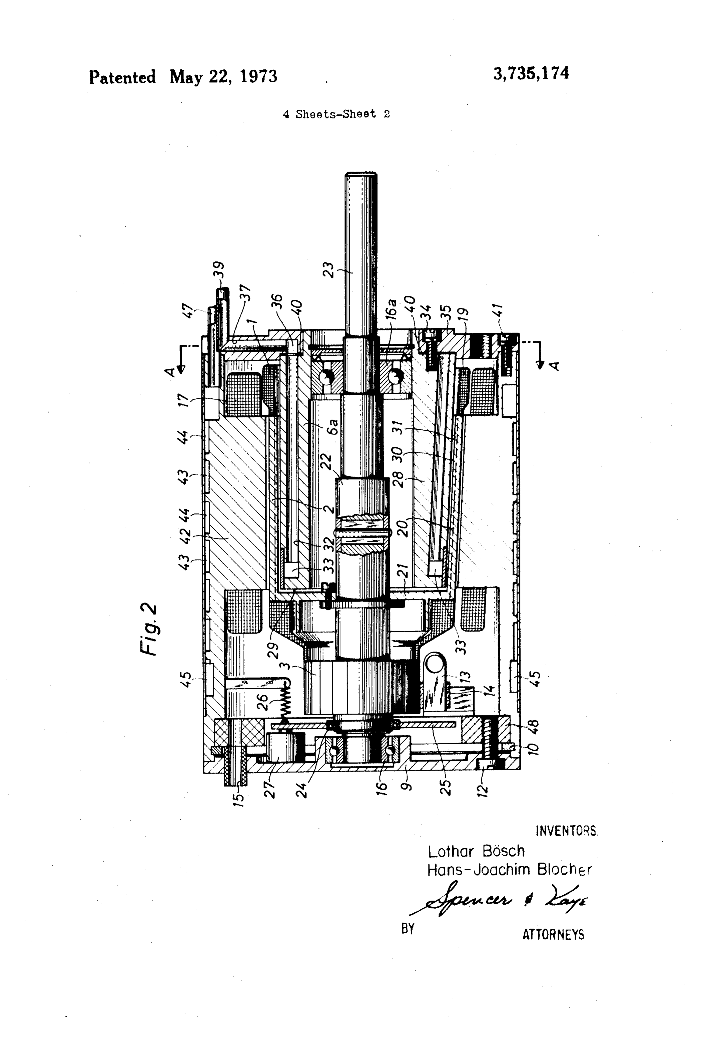
the internal wall of the flange connecting the tubular FIG. 2 is an axial section through a motor with a hol winding support with the sliding sleeve is pressed low rotor, a braking device and cooling channels. The against the front side of the stationary armature core. upper half of the diagram represents a cylindrical wind In another modification of the electric motor the ing support, the lower half a conical winding support as winding support and the stationary armature core are 20 one other possible type of winding support. conical and at least part of the lateral conical area of The cylindrical armature winding 1 is inserted into the stationary armature core is used as the braking grooves of a cylindrical winding support 2 or a conical aca armature winding 19 into grooves of a conical winding In fabricating a winding support of an electric motor 25 support 20 and firmly connected with it through casting with a hollow rotor it is advisable to proceed in such a with plastic resin. The winding support, irrespective of way that grooves corresponding to the arrangement of its shape being cylindrical or conical, is designed as a the windings are made in the outside of a tube and such flange 21 on its side facing the collector 3 and is con an amount of material is machined off the inside of the nected with the sliding sleeve 22 through this flange. tube that the arrangement of the windings still with 30 The sliding sleeve is equipped with guiding elements stands the required mechanical stress. Attachment, engaging into the corresponding guiding elements of resin casting and baking of the winding may be carried the armature shaft 23 and allowing an axial displace out either before or after machining of the inside of the ofment of the sleeve and, at the same time, a transmission tube. torque to be carried out. Also the collector 3 is For groove formation and for increasing the mechan 35 firmly connected with the sliding sleeve 22. Moreover, ical stability, mechanical webs are put on a thin-walled the sliding sleeve carries a control disk 25 on the side tube by one of the methods of hard surfacing, welding, facing away from the winding support through a ball soldering, metal bonding. In this process, the expense bearing 24 which can be loaded axially, which control involved in finishing of the interior of the tube can be disk can be moved axially by a spring 26 in one direc reduced considerably of eliminated entirely. tion and an electromagnet 27 in the other direction. Especially with larger motors it may be advantageous 40 The bore of the cylindrical winding support 2 is filled to cast the winding support and use a casting material with a hollow cylindrical stationary armature core 6a consisting of a mixture of metal particles and an electri or, in the case of a conical winding support 20, with an cally non-conductive binder. If the right type of metal essentially hollow cylindrical armature core 28 which, particles are used, this material has a relatively high 45 however, is conical on the outside, in such a way as to permeability and a practically infinitely high electrical leave only a narrow air gap between the winding sup resistivity. Similar advantages are offered by winding port and the armature core. .
supports pressed out of metal powder and sintered af The spring 26 forces the winding support 2 against terwards. Of course, the winding supports can be made the frontside 29 of the armature core 6a (braking posi
tion), the electromagnet 27 counteracts the spring and
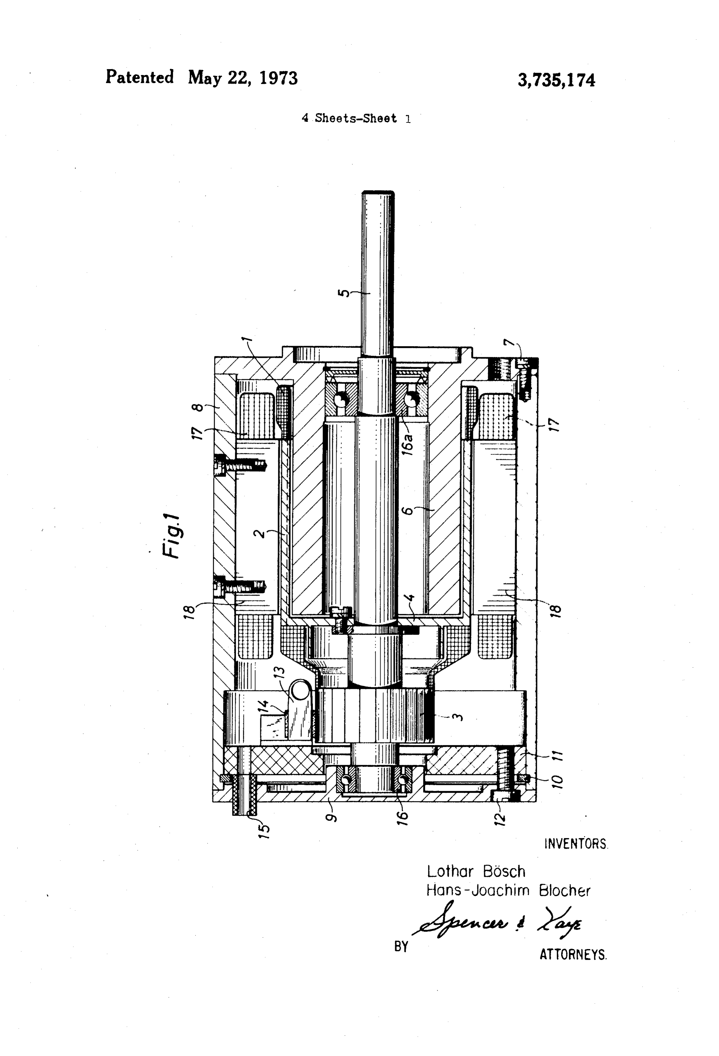
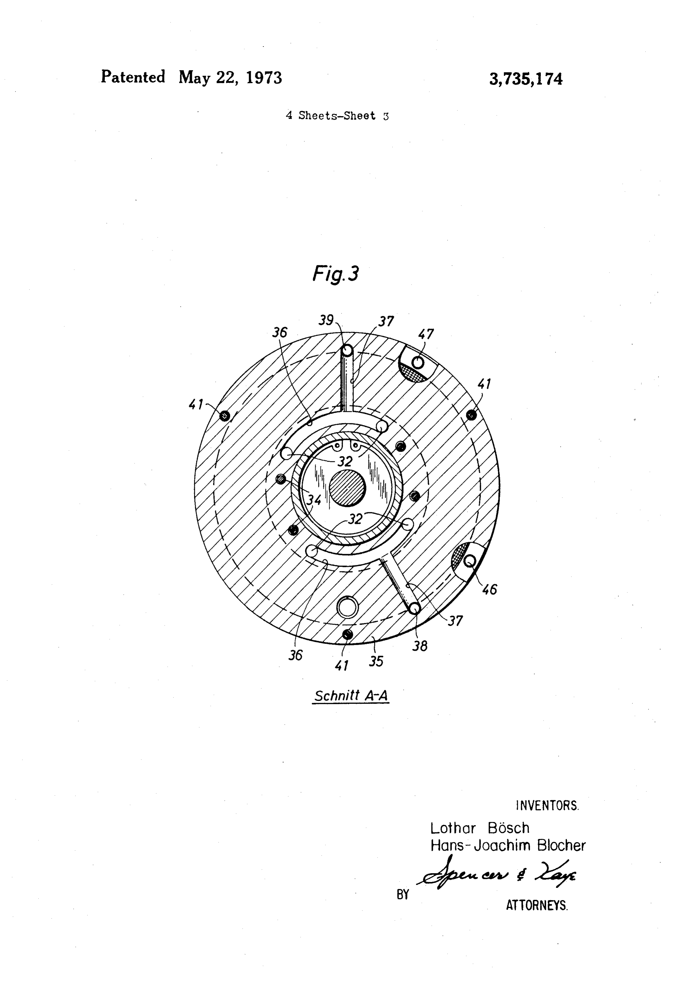
BRIEF DESCRIPTION OF THE DRAWINGS
moves the hollow rotor into the operating position.
In a conical arrangement, the spring and the electro
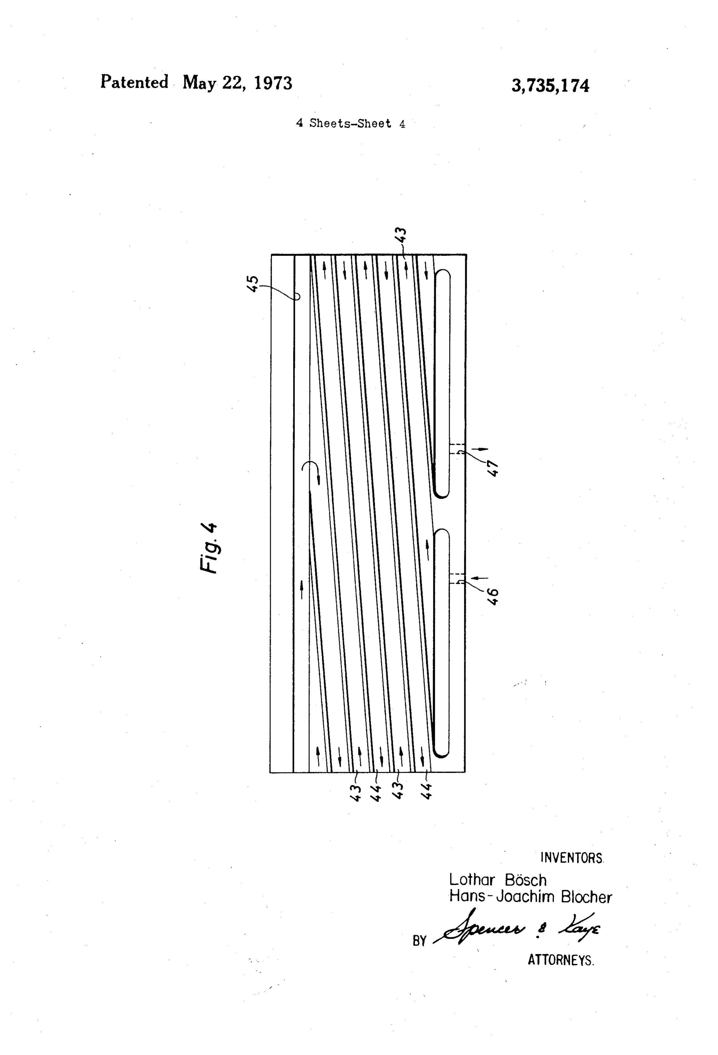
FIG. 1 is an axial section through a motor with a hol magnet act in the same way. However, in the braking low rotor, position, the conical shell areas of the winding support FIG. 2 is an axial section through a motor with a hol 55 30 and of the armature core 31 are forced upon each low rotor with a braking device and cooling channels, other. . FIG. 3 is a section AA with cooling channels, Of course, it is possible also to arrange the spring and FIG. 4 is a development of the exciting core with the electromagnet in such a way that the braking posi cooling channels. tion is attained through excitation of the electromag DESCRIPTION OF THE PREFERRED 60 net. Another possibility is the distribution of several
EMBODIMENTS
springs and several electromagnets on the circumfer ence of the control disk.
In FIG. 1, the armature winding 1 is inserted into As can be seen also from the radial section AA in grooves of a winding support 2 and firmly connected FIG. 3, four axial bores 32 are made in the armature with it through casting with synthetic resin. On the side 65 core 6a and 28, respectively, as close as possible to the facing the collector 3, the winding support is designed shell surface facing the winding support which bores as a flange 4 which connects it with the shaft 5. The are connected with each other on the front side facing bore of the winding support in partly filled by a hollow the collector 3 by means of a radial annular channel 33.
Page 8
A disk 35 is attached to the other front side of the ar The provision of cooling channels in the ferromag mature core by a screwed connection 34. Two channels netic core of the exciting winding and in the armature 36 are machined into the surface of that disk facing the core adjacent to the armature winding also permits a armature core which connect two each of the bores 32 much better ultilization of the windings which, under with each other. Moreover, two radial bores 37 are 5 otherwise unchanged conditions, allows a tenfold in made in the disk 35 each of which ends in one each of crease in motor power. Moreover, the increase in cur the channels 36 and to which the coolant inlet line 38 rent carrying capacity leads to a further reduction of and the coolant outlet line 39, respectively, are con mass and thus of the moment of gyration of the rotor. nected. A flat seal 40 is installed between the armature We claim:
core and the disk 35 for watertight connection of the 10 1. An electric motor of the double air gap type for cooling channels. producing high rated torques and high accelerations The disk 35 also connects the armature core with the with low inertial moment comprising a stationary arma exciting core 42 by means of a screwed connection 41 ture core; a stationary exciting core; an excitation which exciting core accomodates the exciting winding 15 winding associated with said exciting core; an armature 17 and, at the same time, constitutes the motor casing. shaft; a displacement sleeve on said armature shaft, Cooling channels 43, 44 of rectangular cross section said displacement sleeve being displaceable with re are arranged on the periphery of the exciting core and spect to said armature shaft in an axial direction; a thin surround the core like a douple thread. As is evident walled winding carrier having a frontal face in the form from FIG. 4, the coolant flows in a clockwise direction 20 of a flange connected to said displacement sleeve; an in channel 43 and in a counter-clockwise direction in armature winding positioned on said winding carrier; channel 44. Channels 43 and 44 are connected with an axially loadable bearing means; a non-rotatable con each other by channel 45 on the collector side in such trol disk connected to said displacement sleeve via said a way that the cooling water flows through an inlet bearing means for transferring axial movements of said channel 46 into channel 43, from here on into the con 25 control disk to said displacement sleeve; and non necting channel 45 and via channel 44 into the outlet rotatable means separate and distinct from the excita channel 47. tion winding and the armature winding for axially mov On the collector side, the motor is closed with the ing said disk from a first position in which it positions bearing plate 9. The bearing plate and the exciting core said winding carrier in its operating position to a sec 42 serving as a casing are connected with each other 30 ond position in which it positions said winding carrier indirectly through a lock washer 10, a washer 48 of in in a braking position in which at least a portion of said sulating material, a screw 12. The washer 48 carries the winding carrier contacts said armature core. holders 13 of the carbon brushes 14. Electric connec 2. An electric motor as defined in claim 1, wherein tions are led through a bore 15. The bearing plate 9 and said winding carrier is constructed from a material hav the armature core 6a and 28, respectively, are 35 ing a relative magnetic permeability u substantially equipped with ball bearings 16 and 16a to support the greater than 1 and a low electric conductivity and eddy armature shaft 23. current loss.
The advantages arising from the invention lie espe 3. An electric motor as defined in claim 2 wherein cially in the fact that the use of a winding support of the material of the winding carrier comprises sintered higher stability permits higher torques to be transmit 40 metal particles.
ted from the winding to the armature shaft. At the same 4. An electric motor as defined in claim 2 wherein time, the winding support improves the stability of the material of the carrier is a mixture of metal parti shape of the winding. This higher stability of shape al cles and an electrically non-conductive binder. lows a reduction of the air gap to be made whose effec 45 5. An electric motor as defined in claim 1 further tive value is further reduced through the use of a wind comprising cooling fluid channels within said exciting ing support made of a ferromagnetic material. This re core and within said armature core for removing heat sults in a major reduction of the exciting losses and, produced by said exciting winding and said armature hence, a higher useful flux and higher torque at the winding while maintaining the air gaps of the motor same amount of excitation. free of cooling fluid.
Moreover, the winding support according to the in 50 6. An electric motor as defined in claim 1, further in vention permits higher operating temperatures and cluding a motor housing and wherein said means for ax thus a better ultilization at the same component size. ially moving said disk comprises at least one electro The resistance to gamma radiation is also increased magnet fastened to said motor housing and at least one considerably with metallic winding supports, because spring coupled between said motor housing and said the mechanical stability is no longer dependent on a 55 control disk.
hardly radiation resistant plastic material. 7. An electric motor as defined in claim 6, wherein Moreover, quietness of operation is greatly enhanced said at least one electromagnet in its energized state po which is important especially at low speeds in many sitions said control disk in the first position and said at areas of application, least one spring urges said control disk toward the sec Another advantage of the invention is the fact that 60 ond position in which it positions said winding carrier the winding support, because of its stability, can be in the braking position.
used to generate brake torque and the braking devices 8. An electric motor as defined in claim 6, wherein are able to act direct upon the winding support. The said at least one spring urges said control disk toward heat this generates is removed via the metallic winding 65 the first position and said at least one electromagnet in support. This eliminates the need for special brake its energized state positions said control disk in the sec disks to be attached to the armature shaft, which would ond position in which it positions said winding carrier increase the moment of inertia. in the braking position.
Page 9
9. An electric motor as defined in claim 1, wherein having cooling channels disposed in the vicinity of its said stationary armature core includes a free frontal periphery in the direction of its longitudinal axis, said face developed as a braking surface and said flange of cooling channels being connected together by an annu said winding carrier contacts said free frontal face in lar channel in the vicinity of said frontal face; and fur the braking position. 5 ther comprising two arcuate cooling channels in the 10. An electric motor as defined in claim 6, wherein form of portions of a circular arc in said bearing sup said stationary armature core includes a free frontal porting means into which said cooling channels in said face developed as a braking surface and said flange of armature core open thereby combining them into two said winding carrier contacts said free frontal face in groups, and two radial channels in said bearing sup the braking position. 10 porting means which open into said arcuate cooling 11. An electric motor as defined in claim 7, wherein channels for feeding in and removing the coolant. said stationary armature core includes a free frontal 14. An electric motor as defined in claim 1 wherein face developed as a braking surface and said flange of said exciting core is a cylindrical exciting core with two said winding carrier contacts said free frontal face in frontal faces and having cooling channels disposed at
its periphery in the form of a double thread defining a 12. An electric motor as defined in claim 1, wherein first passage and a second passage; and further com said winding carrier and said stationary armature core prising an intake line for coolant connected to said first are conical, at least a portion of the lateral surface of said armature core contacting said winding carrier dur passage coolant at one of said frontal faces, a discharge line for connected to said second passage at said one
frontal face, and an annular channel at the other frontal 13. An electric motor as defined in claim 1, further comprising a motor housing including bearing support face of said exciting core for connecting said cooling ing means, wherein said stationary armature core is in channels. sk k k k the form of a hollow cylinder with a frontal face and
Provenance
- Collection
- Cited prior art
- Original PDF
- patentimages.storage.googleapis.com →
- Filed
- 1970-11-27
- Pages
- 9
- Method
- pdftotext (the PDF's own text layer) + pdftoppm 300dpi page scans
- Source
- Google Patents bibliographic record
- Granted
- 1973-05-22
- Inventors
- L Bosch; H Blocher; Gesellschaft fuer Kernforschung mbH
- Transcribed from
- patentimages.storage.googleapis.com →