patent · US3669751
Electric battery comprising a fuel cell hydrogen generator and heat exchanger
13 June 1972
Page 1
Drawing sheet — no readable text.
Page 2
June 13, 1972 P. D. RICHMAN 3,669,751
ELECTRIC BATTERY COMPRISING A FUE CELL, HYDROGEN
GENERATOR AND HEAT EXCHANGER
Filled March 15, 1967 2 Sheets-Sheet 2 LL LLLL L LLLLL LL LLL LLL LLL LLLSeLLLLL LLL SL LLLLL LSL SLLSLSLLSLL SSLLLLLL SS X
2Z K
I NVEVTOR
Page 3
United States Patent Office Patented June 13, 1972
precise heat and water balances, with external controls 3,669,751 to prevent flooding or drying out of the electrodes.
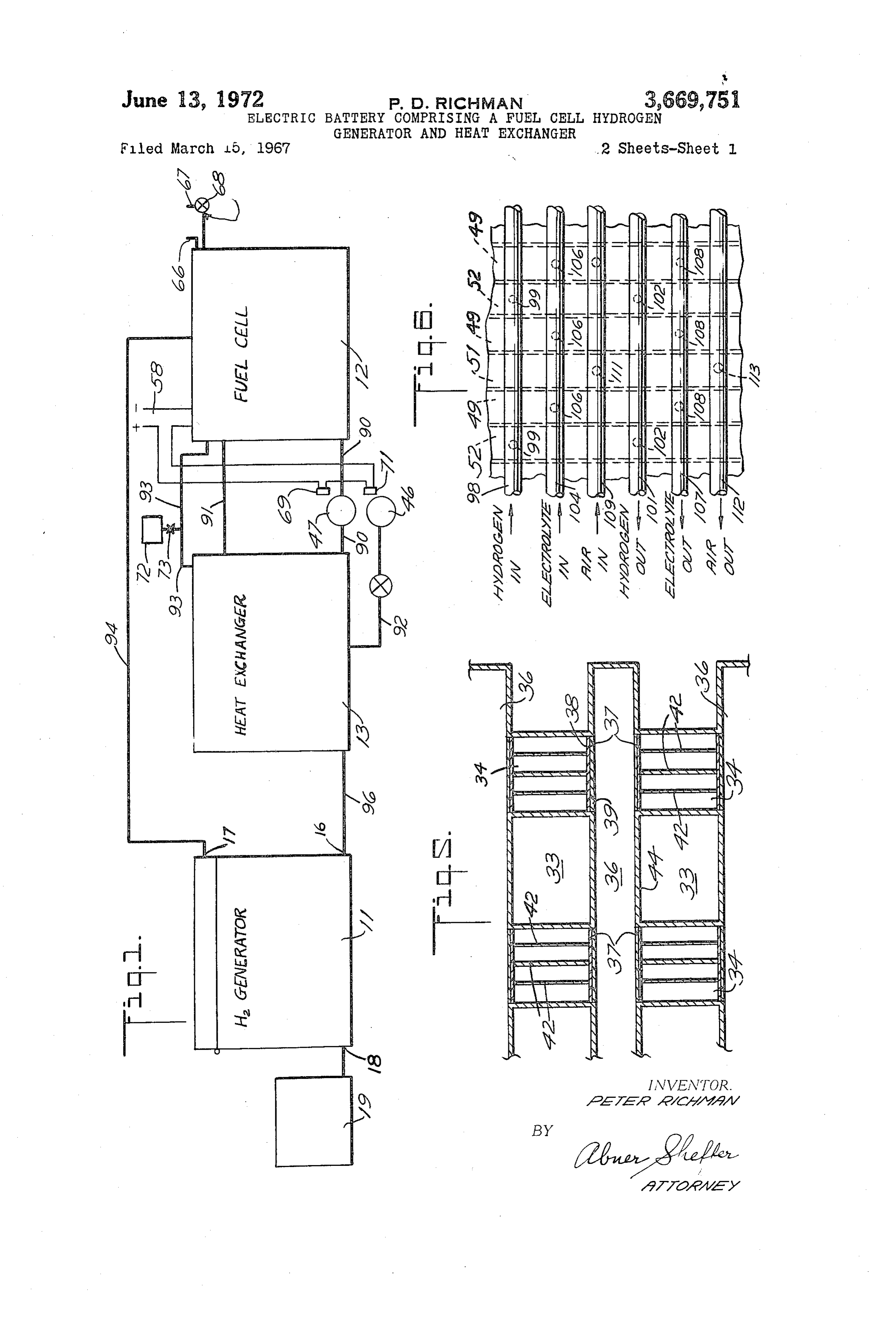
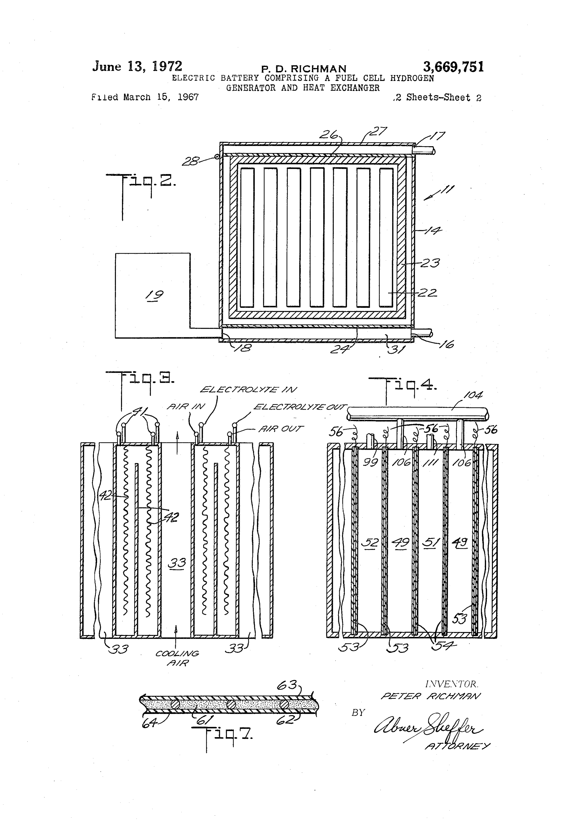
ELECTRIC BATTERY COMPRISING A FUEL One embodiment of the invention is illustrated in the CELL, HYDROGEN GENERATOR AND HEAT accompanying drawings, which are largely schematic and EXCHANGER in which:
Peter D. Richman, 164 Leach Ave., FIG. 1 is an overall side view of the battery system; Park Ridge, N.J. 07656
Filed Mar. 15, 1967, Ser. No. 623,465 FIG. 2 is a cross-sectional side view of a hydrogen gen nt, C. H01m 27/14 erator and reservoir;
U,S. Cl. 136—86 C 22 Clains FIG. 3 is a side view, mainly in cross-section, of a 10 heat exchanger;
FIG. 4 is a plan view, mainly in cross-section, of a
ABSTRACT OF THE DISCLOSURE fuel cell;
An electric battery of very high capacity per pound. FIG. 5 is a cross-sectional plan view of a typical por tion of the heat exchanger;
The preferred embodiment is a self-balancing system FIG. 6 is a plan view of a portion of a fuel cell, illus having a hydrogen-oxygen fuel cell, a circulating KOH trating a manifold arrangement; and - electrolyte and a hydrogen generator in which an Si-Al FIG. 7 is a cross-sectional view of an electrode use mixture is reacted with the electrolyte to produce hydro in the fuel cell.
gen and an insoluble aluminum silicate, thus taking up The battery illustrated in the drawing has two principal the water generated in the fuel cell. In the fuel cell the 20 units, a hydrogen generator 11 and a fuel cell 12 where electrodes preferably have a hydrophobic surface on the the hydrogen from the generator is used to produce elec gas side and a hydrophilic bubble barrier on the electro tricity by reaction with oxygen. The electrolyte used in lyte side. the fuel cell is also present in the hydrogen generator, where it takes part in a hydrogen-producing reaction, and where its water content is diminished, thus consum
This invention relates to electric batteries and to fuel 25 ing cells. the water produced by the hydrogen-oxygen reaction of the fuel cell.
Even the best of the newly developed electric batteries For many purposes, and particularly when the fuel arie quite heavy in relation to their electrical output. cell is to be run at high rates, the battery includes, as a See, for example, the recent article by Hoffman on 30 third principal unit, a heat exchanger 13 through which “The Electric Automobile” in Scientific American, Octo electrolyte circulates for the removal of excess heat gen ber 1966, pp. 34-40, where it is stated that "even the very costly silver-zinc batteries developed for the elec erated by the reaction in the fuel cell. The heat exchanger may also serve to treat the incoming air in a desirable trical systems of space vehicles are good for 30 watt-hours manner before it is admitted to the fuel cell by saturat per pound,” and where the author predicts that "before ing this air with moisture, preheating it and removing long . . . development will produce metal-air batteries 35 carbon dioxide therefrom; these functions are performed with an energy density of 60 watt-hours per pound or by bringing the incoming air into reactive and evapora even higher.” tive contact with the electrolyte removed from the fuel Batteries made by combining a fuel cell with stored hydrogen have also been suggested in the art and, in fact, 40 cell.
a fuel cell supplied with hydrogen has been employed in In the preferred embodiment of the invention, the elec the flights of the Gemini space capsule (see "Proceedings trolyte is an aqueous solution of a base, preferably potas 20th Annual Power Sources Conference,' articles by sium hydroxide, and the material used to react therewith R. Cohn on "Gemini Fuel Cell System.” This system too to produce the hydrogen is a mixture of silicon and alu gives a relatively low output per pound. 45 minum. I have found that this mixture reacts with the Combinations of fuel cells and hydrogen generators, aqueous KOH to produce an insoluble potassium alu such as steam reformers for converting hydrocarbons to minum silicate; for example, according to the following hydrogen, have been designed, as reported, for example, equation:
by Kirkland in an article at pages 35-38 of "Proceedings 20th Annual Power Sources Conference.' Such systems 50 are quite complex and also give a relatively low electrical This reaction product is insoluble in the electrolyte and output per pound.
According to one aspect of the present invention, I does not contaminate it, so that the electrolyte can be have developed a fuel cell battery system which has the recirculated to the fuel cell after the reaction without an capability of delivering a high electrical output. Further 55 adverse effect on the operation of the fuel cell. It will be more this battery system can be quickly, easily and sim seen from the above equation that the same reaction also ply refueled at a fuel cost comparable to the prices paid the consumes a considerable amount of water, thus raising by consumers for electricity obtained from a central KOH concentration in a desirable manner. power station. The fuel used is inexpensive, plentiful, remove The aqueous KOH also serves, in one embodiment, to lightweight and easily and safely handled. The capital 60 exchanger, undesired CO2 from the incoming air in the heat costs of my battery system are also very much lower, according to the reaction: for similar power and capacity, than those of the prior art.
My invention makes it possible to construct battery sys tems of very high capacity per pound which are capable In the preferred embodiment the hydrogen generator of starting readily at an ambient temperature as low as 65 is constructed to operate, automatically, in a pulsating -20 F. or less and even after being held inactive, in manner so that there is a repeated variation in the pres standby condition, for long periods; which are capable sure of hydrogen fed to the fuel cell. The pulsations aid of operating efficiently and continuously over a very wide in the operation of the fuel cell.
range of discharge rates; and which have a very long Turning now to the details of the illustrated hydrogen life. The systems are essentially self-regulating and use 70 generator 11, it comprises an imperforate outer casing 14 a minimum of external controls, in contrast to existing (FIG. 2) having an opening 16 for passage of the electro fuel cells which require the maintenance of delicate and lyte, an outlet 17 for the hydrogen and an inlet 18 for
Page 4
receiving additional electrolyte (as from a reservoir 19). can drive the electrolyte level below the units and stop Solid hydrogen-producing units 22 (preferably of an Al the reaction entirely. The use of hydrogen by the fuel ceil Si mixture, as previously described) are situated within causes the pressure in the generator 11 to drop, permitting the outer casing 14, preferably being mounted in spaced the electrolyte level therein to rise and start the reaction relationship on a suitable support such as a rack or a again. The presence of the bubble barrier 24 prevents the basket or permeable container 23; thus, when the units intrusion of the hydrogen gas into the space 31 beneath it. 22 have been spent they may be removed with their Bubble barriers of known construction, made of material support, as a single package, from the outer casing 14 resistant to the electrolyte (e.g. polytetrafluoroethylene, and a replacement package, comprising an identical Sup polyvinyl chloride, Kynar polyvinylidene fluoride or port carrying a plurality of fresh units 22, may be inserted, O Penton poly-OC(C2)-) and having controlled pore thereby recharging the battery. sizes, may be employed. One suitable bubble barrier has Between the electrolyte passage 16 and the units 22 a pore size of 6 microns and is capable of withstanding a there is a porous bubble barrier 24 which helps to prevent “bubble pressure' of about 5 p.s.i.; that is, the first gas the generated hydrogen from backing up into the electro bubble will pass through the barrier when the pressure lyte below the barrier. Above the units 22 there is a hydro 5 difference between the gas (on one side of the barrier phobic filter 26 which permits the passage of hydrogen and at the higher pressure) and the liquid (on the other gas but blocks the passage of electrolyte and any solids side of the barrier) reaches about 5. p.s. i. or higher. that may be dispersed therein, thus preventing the hydro The hydrophobic filter 26 preferably has a surface of gen from being contaminated by foam or spray resulting a hydrophobic polymer resistant to degradation by the from the hydrogen-producing reaction. This filter 26 20 electrolyte, such as polytetrafluoroethylene or similar ma may be supported on the cover 27 of the outer casing 14, terial of high-fluorine content. Filters of this nature are which cover may be hinged, as at 28, so that it can be commercially available.
swung upwards to permit the removal and replacement of The electrolyte reservoir. 19 may be connected to the the hydrogen-producing units 22. hydrogen generator 11 by means of the free passageway, The units 22 are preferably porous and not very thick; 25 18 so that the electrolyte is supplied to the generator from they may be circular. cylindrical rods about 2 cm. in the reservoir automatically, as by gravity feed, as needed diameter made by compacting a mixture of finely divided (or any excess electrolyte is taken up in the reservoir). It particles of silicon and aluminum. Their porosity and will be understood that, instead of using a separate electro limited thickness permits the aqueous electrolyte to pene lyte reservoir 19, reserve space for electrolyte may be trate to the center of the rods without being blocked by 30 provided within the housing 14 of the hydrogen gener the gelatinous potassium aluminum silicate reaction prod ator 1.
uct. The porosity of the rods provides space for the In the illustrated embodiment the passage 16 serves not reaction product while the rod maintains its coherent only as an inlet through which the water-diluted electro nature, and its shape and form; thus when the reactive lyte (carrying water picked up by it in the fuel cell) enters material of the rods is used up, the spent rods can be 35 the hydrogen generator 11, but also as an outlet for the. readily removed, for replacement. The chemical com passage of the electrolyte of lower water content out of ponents of the rods need not be in the pure state; for ex the hydrogen generator. Thus, with respect to the electro ample, commercial ferrosilicon containing about 92% lyte in the fuel cell 12 and heat exchanger 13, the hydro silicon and 7%% iron has been used with good results; the 40 gen generator constitutes a sort of bay, there being little presence of the iron has produced no adverse effects on or no Current of liquid in the passage 16; much of the the reaction. transport of material occurs by diffusion, with the KOH Aside from the fact that it forms an insoluble reaction diffusing (owing to the concentration gradient) out of product which does not contaminate the electrolyte and the hydrogen generator 11. It is of course within the which includes substantially all of the water produced in Scope of the invention to provide means for positively the fuel cell, the aluminum-silicon combination has other 45 circulating generator.
the electrolyte into and out of the hydrogen advantages. It is extremely light in weight. Unlike a unit made solely of silicon, it is practically immediately re In the illustrated heat exchanger 13 (see FIGS. 3 and active with the electrolyte; I believe that the aluminum 5) the hot electrolyte from the fuel cell 12 flows in a begins reacting almost at once and the rise in temperature, Serpentine path and is brought into evaporative and resulting from the exothermic heat of reaction, increases 50 Scrubbing contact with the reactant air (i.e. the air to be the reactivity of the silicon. Also the use of the aluminum Supplied to the fuel cell). At the same time, additional silicon combination avoids the retardation of the reaction air is passed through the heat exchanger, out of contact which occurs (probably due to the presence of dissolved with the electrolyte, to remove heat by convection. As silicon in the aqueous medium) when silicon alone is shown in FIGS. 3 and 5, there are a series of vertical used. The presence of iron, as in ferrosilicon, also pro 55 cooling air passages 33 (which may be rectangular, e.g. motes the hydrogen-producing reaction. The reaction of Square, in cross-section), a series of vertical reactant air the Al-Si mixture with the electrolyte removes from the passages 34, and another series of vertical electrolyte electrolyte an amount of water just about equivalent to passages 36, the electrolyte passages 36 being separated the amount of hydrogen generated by that reaction, mak from the reactant air passages 34 by special porous bar ing the system substantially self-balancing with respect to 60 riers 37 which block the movement of the electrolyte there Water; if aluminum alone is used, the reaction consumes a through but permit the transport of gases such as air greater amount of water, and a relatively large amount and water vapor. These barriers 37 may be made of a of water must therefore be continuously added to the composite structure comprising a gas-permeable hydro System. The formation of the gelatinous reaction product 65 phobic layer 38 which prevents passage of the electrolyte will also tend to have a desirable effect in purifying the into the gas space 34 and a hydrophilic layer 39 which electrolyte by trapping impurities in its lattice structure. is permeable to, and wet by, the aqueous electrolyte but The illustrated construction automatically balances the whose pores are so small that, when so wetted, they resist penetration of the gas into the electrolyte space operation of the hydrogen generator in accordance with the hydrogen utilization in the fuel cell, which is in turn 36. In passing along the barriers 37 the reactant air is heated almost to the temperature of the entering electro governed by the electrical load on the battery. As the 70 lyte, pressure of hydrogen builds up the gas pushes the electro becomes substantially saturated with moisture at lyte downward, thus reducing the area of contact between that elevated temperature, and loses substantially all its the electrolyte and the units 22 and thereby decreases the
CO2 content by reaction thereof with the electrolyte form ing K2CO3, as indicated previously, which may be de rate of generation of hydrogen. The increase in pressure 75 posited in or along the barriers 37. By means of suitable
Page 5
manifolding (indicated schematically as 41) and baffles blower and pump at a speed generally proportional to indicated schematically as 42), the reactant air (and the current delivered by the battery to the load. When electrolyte if desired) are made to follow serpentine coun Substantially undiluted oxygen (which may be supplied tercurrent paths so that the reactant air just about to from a storage tank 72 under pressure) is used in place be fed to the fuel cell is brought into the evaporative of air the control valve 73 for the supply of oxygen may contact with the hot electrolyte just leaving the fuel cell. be similarly regulated in response to the electrical demand The elevated temperature also assists the reaction of the on the battery (the blower 46 being disconnected or re carbon dioxide and the electrolyte. moved).
The walls 44 bounding the cooling air passages 33 are The pre-humidification of the reactant air (or oxygen) made of suitable heat-conductive material, such as nickel O minimizes the danger of undesirable dehydration of the or nickel-plated magnesium, to facilitate heat transfer electrodes even when the rate of flow of these reactants from the electrolyte through these walls. is too high.
In the fuel cell 12 (see FIGS. 1 and 4), there are In making the fuel cell electrodes, one may use the con brought together the preheated, saturated, scrubbed re structions described in Unclassified Document AD 611 actant air from the heat exchanger, the electrolyte from 5 558-"A New High Performance Fuel Cell Employing the heat exchanger, and the hydrogen from the hydrogen Conducting-Porous-Teflon Electrodes (Niedrach-Alford) generator. A blower 46 serves to force the reactant air and Liquid Electrolytes” by L. W. Niedrach and H. R. through the heat exchanger 13 and into the fuel cell, Alford, published by and available from Clearinghouse while the cooled electrolyte from the heat exchanger is for Federal Scientific and Technical Information, U.S. delivered to the same fuel cell by a pump 47. The pump Department of Commerce, which describes catalyst mix also serves to maintain the electrolyte in the fuel cell 12, tures, conductive screens and hydrophobic films, which the heat exchanger 13 and the hydrogen generator 11 may be employed. As previously mentioned, the preferred under a positive superatmospheric pressure. form of my invention uses also an electrolyte-permeable In the illustrated embodiment, the electrolyte, air and layer 64 (which is not described in the Niedrach et al. hydrogen in the fuel cell pass through parallel thin 25 publication). This may be made of a material which is chambers 49 (FIG. 4), 51, 52, being separated from each readily Wetted by the electrolyte but resistant to attack other by the electrodes 53 and 54. Each electrolyte cham thereby, having pores of such size that the electrolyte in ber 49 is situated between an air chamber 51 and a the pores blocks the passage of bubbles of the gas. For hydrogen chamber 52. The electrode 53 which acts as example, a film of polyvinyl chloride about 5 to 10 mils the anode serves as the boundary between the hydrogen 30 thick and having a pore size of about 6-7 microns may and electrolyte chambers (52, 49), while the electrode be employed; it may be adhered to the face of the elec 54 which acts as the cathode constitutes the boundary trode (opposite to the face carrying the hydrophobic between the air and electrolyte chambers. The electrodes film) by sparying that electrode face with an adhesive are connected through suitable electrical conductors 56 (such as a toluene solution of rubber), then placing the to the battery terminals 58 in well-known manner. 35 film) by spraying that electrode face with an adhesive In one preferred form of the invention, both electrodes for at 325 F.) and pressure. The amount of adhesive used are made up of a thin bed of catalyst 61 (FIG. 7) sup this bonding should of course be as small as possible, ported in electrically conductive contact with a current philicso that it does not unduly block the pores of the hydro collector, which may be a screen such as a wire mesh 40 occur during film. Generally some blockage of the pores does 62 between a porous hydrophobic layer 63 (on the gas bonding, due to the presence of the adhesive side of the electrode) and a porous hydrophilic layer 64 and also as a result of flow of the film material under the (on the electrolyte side of the electrode). The hydrophobic high pressures which may be used in the bonding step; layer 63 permits the gas to pass therethrough into contact for best results one may compensate for this by choosing with the catalyst bed 61 which is wet with the electrolyte, a film having an appropriate pore size (determined by but blocks any flow of electrolyte, or of water of re preliminary tests of the adhesive-bonded structures, using films of various pore sizes) such that the film after bond action, from the catalyst bed to the gas chamber 51 or ing is receptive to, and freely permeable by, the aqueous 52 and thereby reduces flooding of the gas chambers.
medium and, when wet with said medium, has a “bubble
The hydrophilic layer 64, on the other hand, is permeable pressure' to the electrolyte and thus keeps the catalyst bed wet with higher than the expected peak hydrogen pres Sure to which electrolyte (in effect, drawing the electrolyte into contact fuel cell. The same 50 it will be subjected during operation of the with the bed by capillary action), but is impermeable to types of hydrophilic and hydrophobic the gas, preventing the gas from bubbling into the elec layers may be employed in the barriers 37 of the heat trolyte chamber 49. The catalyst bed 61 itself is pref eXchanger.
erably very thin, having a thickness of less than about The presence of the hydrophilic layer 64 which serves 0.02 inch (e.g. 0.004 inch), and the overall thickness of 55 as a bubble barrier (having, for example, a hydrogen bub the electrodes is not much greater (e.g. 0.008 inch). ble pressure of 3 to 5 p.s. i.) gives the electrode structure The fuel cell 12 has an air vent 66 and also has a the ability to operate with assurance over a wide range of hydrogen vent 67, controlled by a valve 68, for the hydrogen pressures without the need for extensive ex periodic, controlled discharge of any inert contaminating ternal controls; this is particularly desirable in the illus gases in the fuel cell, as is well known in the art. The 60 trated construction in which the pressure of hydrogen hydrogen vent valve 68 may be a pressure-responsive from the generator may vary considerably, as previously valve preset at a level predetermined by the operation described. The system is thus in effect auto-balancing, of the hydrogen generator so as to permit discharge of since it accommodates itself to the conditions created by hydrogen through valve 68 only when the pressure in the electrical demand on the fuel cell, the ambient tem the fuel cell approaches the predetermined peak of the 65 perature and the previous history of the system, without pressure generated by the hydrogen generator, or only using expensive, heavy, external controls. The two mem when the hydrogen pressure approaches or exceeds the branes, on the opposite sides of the catalyst bed, main “bubble pressure" value of the bubble barrier 24 of tain the electrolyte and reactant gases in their proper the hydrogen generator. relationship to each other automatically owing to the The air blower 46 and electrolyte pump 47 are electrical 70 intrinsic surface energies of the membranes. Films having ly connected to the fuel cell in such fashion that they interconnecting pores suitable for use as hydrophilic operate only when electric current is demanded (by the bubble barriers may be manufactured by well-known external load); preferably these electrical connections techniques (e.g. by forming the film by evaporating the (indicated as 69, 71) are of a well known current solvent from a solution of a high polymer in the presence monitoring type, to drive the electric motors of the of a solvent-miscible non-solvent, such techniques and
Page 6
films being described in U.S. Pat. 2,944,017 of July 5, The hydrophobic film component of the electrode 1960 and the references mentioned therein) and are also should be as thin as practical with as small a pore size available commercially. Generally it is preferred to use a and as great a total porosity as possible. A membrane material whose pores occupy at least 50%, preferably having an approximate average pore size of about 2 at least 60% of the total volume of the film. One com microns, a porosity of about 65% and a thickness of mercial material is Millipore Corporation's Polyvic Type about 3 to 5 mills (i.e. 0.003-0.005) has given very good BC, a flexible polyvinyl chloride film about 9 mils thick results. The specific hydrophobic films described in the having a pore size of about 6 microns. Another hydro previously cited references may be used, as may be the philic material is porous polyvinylidene fluoride film. Al film known as Mitex filter sheet material (sold by Milli though the polyvinylidene fluoride in bulk form is itself O pore Corporation), comprising a continuous mat of Teflon not a hydrophilic material, when it is in suitable porous (TFE) fibers which are fused together at each fiber inter film form, however, its structure is such that the aqueous section to prevent structural distortion. medium is sucked into and held within the pores by capil The preferred electrodes are extremely light in weight lary action and the film thus carrying the aqueous medium (e.g. their weight may be less than about 30 grams per is resistant to the passage of gas bubbles through its pores. 5 Square foot) and they function to supply a high surface The distances between the electrodes 53, 54 on opposite area reaction zone. The efficiency of fuel utilization and sides of each electrolyte chamber are preferably small, the electrical capacity of the system are largely independ preferably less than 0.1 inch, e.g. on the order of 0.05 inch ent of discharge rate. For example, the difference between or less. Smaller distances desirably decrease the electrical the polarizations at the hydrogen electrode at discharge resistance of the electrolyte chambers. 20 rates of 100 amps./ft. and 500 amps./ft.2 is often as small Catalyst beds for use in the electrodes are well known as 50 mv., or 5% of the voltage per cell. in the art (see, for example, the cited Niedrach et al. pub The voltage generated between each pair of electrodes, lication and the Christopher article in "Proceedings 20th in the preferred system, is about 0.7–0.8 (depending on Annual Power Sources Conference,” pp. 18-21). Thus, the discharge rate). As is conventional in the fuel cell they may be composed of a mixture of fine particles of an 25 and battery arts, the large number of individual pairs electrocatalyst such as platinum black or other electro of electrodes in the fuel cell may be electrically intercon catalytic metal (e.g. palladium, silver, nickel), which nected in various series and parallel arrangements to may be supported on a carrier (e.g. platinum on a carbon attain the desired voltage and current-delivering capacity carrier), and fine particles of a hydrophobic material re at the output terminals of the fuel cell. sistant to the electrolyte, such as polytetrafluorethylene; 30 As indicated by the equation set forth above, the pre typically the electrocatalyst is made up of agglomerates ferred hydrogen-generating units consume about 22 moles of particles on the order of 0.01 micron in diameter and of water to produce 21 moles of hydrogen gas. Some the polytetrafluoroethylene particles are less than 1 mi additional water is also supplied by the reaction of the cron (e.g. 0.2-0.5 micron) in diameter. The use of the carbon dioxide of the air with the electrolyte. The pres hydrophobic particles in admixture with the electrocata 35 ence of the aqueous KOH in the reservoir 19 aids in main lyst yields a bed structure which is permeable to both the taining the water balance, and its water content com gas and the aqueous electrolyte; in this structure the liquid pensates for any overall loss of water. Thus, unlike con gas meniscus reverses its direction between a hydrophilic ventional fuel cell systems in which there must be close electrocatalyst surface and a hydrophobic polytetra control and removal of water by special mechanisms, my fluorethylene surface spaced from, but very near, said 40 system can be operated using a simple addition of wate electrocatalyst surface. at a predetermined location.
The electrocatalyst bed may be formed in known man The aqueous solution of KOH preferably has a concen ner from a suspension of fine particles of previously tration of about 30-35%, although more dilute solutions formed electrocatalyst (e.g. platinum black) and fine (e.g. 15%) or more concentrated solutions (e.g. 4.5%) particles of the hydrophobic polymer in water or other 45 or even substantially saturated solutions may be em suspending medium for the bed-forming material; the ployed. Other bases may be used, less preferably, e.g., electrocatalyst may, if desired, be deposited onto the NaOH or LiOH.
surfaces of fine carbon particles (e.g. platinum on car In the heat exchanger, the hydrophilic and hydrophobic bon) which particles are then added to said suspending porous layers 38, 39 may be composed of films of the medium; also, the electrocatalyst may be deposited (as same materials as are used in forming the electrode struc by chemical reduction) onto the surfaces of particles of 50 tures. They may be suitably supported in any desired hydrophobic polymer which may themselves be in the manner; for example, they may be bonded to opposite suspended condition. The relative proportions of electro sides of a thin wire mesh supporting screen, e.g., a nickel catalyst and polymeric material may be, for example, woven wire screen about 5 mils thick, so that there is a within the range of about 9:1 to 1:1, preferably about 2:1 55 small space between the two films; or they may be to 4:1. The thickness of the deposited bed and of the bonded in face-to-face contact. current collector screen may be, for example, within the It will be appreciated that instead of using the elec range of about 0.001 to 0.1 inch.
Mixtures of hydrophobic polymer and electrocatalyst changer,tothescrub trolyte the COs from the air in the heat ex are also described in the book "Fuel Cell Systems, Ad 60 scrubber, which may ofbeCO2 removal may be affected in a separate vances in Chemistry Series, 47" published 1965 American thermally rechargeable type or known of well type (e.g. of the
Chemical Society, pages 106-115. Teflon dispersion poly type) and through which the air may be passed,hydroxide the lithium mers and aqueous dispersions of polytetrafluoroethylene ample prior to its entry into the heat exchanger. for ex are described in Kirk-Othmer Encyclopedia of Chemical The hydrogen-producing units may be produced by Technology (2nd ed.), vol. 9, pages 813-817. 65 conventional techniques of powder metallurgy or ceramic The porosity of the catalyst bed may be increased by production, e.g. by forming a mixture of the Al - and Si incorporating fine particles of a solid extractable filler powders in a mold at a temperature, and pressure, suffi in the aqueous suspension of catalyst (e.g. about 5-70% cient to sinter the particles together to form a porous rod. of particles of aluminum of about 0.1-10 micron diam In another method the Al and Si powders are mixed eter); this filler may be subsequently removed, as by 70 with a material which imparts plastic extrudability to leaching with aqueous KOH. The suspension of bed-form the mixture (e.g. a wax or resin, such as polystyrene) and ing particles may be a relatively stable one (e.g. one which the resulting plastic mixture is continuously extruded takes about 1 to 10 days to settle) or relatively unstable to form a continuous rod; then all or part of the added (settling after, e.g., 15 minutes of standing at room tem material is removed, as by heating the rod to evaporate perature). 75 off or decompose the added material while sintering the
Page 7
remaining particles together, or by treating the rod with Si+Al--KOH--HO a solvent for all or part of the added material. Alterna reaction using equiatomic amounts of Si and AI) one tively the powder mixture may be contained in a porous container; for example a mixture of particles, of size Which consumes slightly more water than is generated by small enough to pass a 100 mesh (U.S. Standard) screen, the fuel cell. Makeup water is also provided by the KOH may be tamped into a porous tube of polymethylmeth Storage reservoir shown in the drawings, as previously acrylate plastic and used as a hydrogen-producing unit. mentioned.
(Incidentally, the reaction with the electrolyte will cause The exothermic heat resulting from the hydrogen-gener such particles to adhere together forming a unitary spent ating reaction often heats the hydrogen to a temperature rod which can be removed readily from its porous con O approaching, or exceeding, the usual operating tempera tainer.) Other materials may be present in the Si-Al hy ture of the fuel-cell. The heated hydrogen may, if desired, drogen-producing units, e.g. promoters such as described, be passed, on its way to the fuel cell, through a heat ex or other substances which may serve to bind the particles changer where part of its heat is used to preheat the re together or control the porosity of the rods (e.g. organic actant air prior to the entry of the latter into the electro polymers). 5 lyte heat exchanger previously described. The mixture of silicon and aluminum, which are each The hydrogen generator, heat exchanger and fuel cell in the reduced state, may be present in the form of an may be constructed as separate modules, which can be alloy, or in the form of an intermetallic compound or a assembled into a unitized battery package in such a man. so-called silicide. It may include other metals capable of ner that any one of the modules can be readily replaced. reacting with water, under the same conditions, to liberate 20 Thus able the conduits joining the modules can each have suit.
intermediate couplings, of known construction, with hydrogen from the water (e.g. 5-30% of sodium, potas a shut-off valve in each conduit adjacent its coupling, so sium, lithium, calcium, etc.); the added metal (e.g. potas that any module can be operatively isolated from the sium) will also supply a constituent of the insoluble re others by closing the appropriate shut-off valves and then action product and thereby reduce or eliminate the previ ously described loss of potassium from the electrolyte. 25 decoupled, after which the module thus isolated can be For example, a powdered alloy of the aluminum, the removed and an identical replacement module coupled silicon and the potassium may be shaped into desired into the system in its place.
porous rods; or the rods may be made of a mixture of As illustrated in FIG. 1 of the drawing, the conduits 90 a powdered alloy of the aluminum and the potassium, and 91 serve for the passage of circulating electrolyte be with powdered silicon (or ferrosilicon); or the rods may 30 tween the heat exchanger 13 and the fuel cell 12, the be formed from a mixture of a powdered alloy or com circulation being effected by means of the pump 47. The pound of the silicon and the potassium, with powdered conduit 92 serves for the air fed (from blower 46) to aluminum, etc. the heat exchanger 13. The conduit 93 serves for the If desired, there may be a vertically non-uniform ar passage of air from the heat exchanger to the fuel cell rangement of the hydrogen-producing units. Thus the po 35 (or, when desired, for the passage of OXygen from tank rosity or density of the units or the particle size of the pow 72 to the fuel cell). The conduit 94 serves for the passage ders making up the units may vary along their lengths; of hydrogen from the outlet 17 of generator 11 to the for example, smaller particles may be used for the bottom fuel cell. The conduit 96 serves for the passage of elec portions than for the tops of the units. trolyte from the heat exchanger to the electrolyte opening 40 16 of the hydrogen generator 11; as previously indicated
It is also within the broader scope of the invention to the hydrogen generator constitutes a sort of bay with employ the aluminum or silicon alone. In this case, the respect to the electrolyte in the fuel cell 12 and heat ex resulting soluble reaction products will contaminate the changer 13. So that the passage 16 serves not only as an electrolyte, and have some adverse effect on the fuel cell inlet through which the water-diluted electrolyte (carrying reaction, but this effect can be tolerated especially when Water picked up by it in the fuel cell) enters the hydro the cell is used in situations where only a short term sup 45 gen generator 11, but also as an outlet for the passage ply of power is needed. Also, it is within the broader scope of the eelctrolyte of lower water content out of the hydro of the invention to use the aluminum and silicon, alone or gen generator, there being little or no current of liquid together, to generate the hydrogen in a system in which there is no direct communication between the electrolyte . in the passage 16 and conduit 96; much of the transport in the fuel cell and the aqueous alkaline solution reacting 50 of material occurs by diffusion, with the KOH diffusing (owing to the concentration gradient) out of the hydro with these elements. For example, with fuel cells of known type in whose operation the water of the fuel cell reaction gen generator 11. Also, as previously indicated it is within does not mix substantially with the electrolyte but runs the Scope of the invention to provide means for positively down the gas side of the electrodes and is separately col circulating the electrolyte into and out of the hydrogen lected, the collected water may be supplied to the hydro 55 generator, and it is to be noted that the two principal gen generator (being gravity-fed, for example, through the units of the battery are the hydrogen generator and fuel same inlet as is used in the illustrated embodiment for the cell, although for many purposes (particularly when the feed of the water-rich electrolyte from the fuel cell and fuel cell is to be run at high rates) the battery does in heat exchanger), and the resulting hydrogen may be Sup clude the heat exchanger as a third principal unit. plied from the generator to the fuel cell in the same pull 60 As mentioned previously, FIG. 4 is a plan view of a sating manner as previously described. In such a system fuel cell mainly in cross-section, while FIG. 6 is a plan the aqueous material in contact with the aluminum need view of a portion of a fuel cell illustrating a manifold ar not be alkaline; for example, it may be a solution of a rangement. More specification FIG. 6 shows a hydrogen mercuric salt (e.g. mercuric chloride, in about 1% con inlet manifold 98 (which is an extension of hydrogen feed centration). In its still broader, but less desirable aspects, 65 conduit 94) having individual hydrogen feed pipes 99 my invention can employ highly reactive light elements, connected to the individual hydrogen chambers 52; a hy such as alkali metals or alkaline earth metals, as the water drogen outlet manifold 101 having individual exit pipes reactive hydrogen-producing elements, alone or in com 102 connected to other portions of said chambers 52; an bination with each other or with the aluminum or silicon. electrolyte inlet manifold 104 having individual electrolyte The illustrated embodiment of the invention may also 70 feed pipes 106 connected to the individual electrolyte be operated under conditions in which a portion of the chambers 49; an electrolyte outlet manifold 107 having water of reaction condenses in the gas spaces of the fuel individual electrolyte exit pipes 108 connected to other cell. A line may be provided for transporting this collected portions of said chambers 49; an air inlet manifold 109 water to the hydrogen generator, particularly when the (which is an extension of air feed conduit 93) having hydrogen-producing reaction is (like the 75 individual air inlet pipes 111 connected to the individual
Page 8
air chambers 51; and an air outlet manifold 112 (leading the operation of said fuel cell, and means for removing to air vent 66) having individual air outlet pipes 113 con heat from said removed diluted electrolyte, said transport nected to other portions of said chambers 51. It will be means including means for returning cooled electrolyte understood that the electrolyte inlet manifold 104 receives to Said space while maintaining said electrodes continu cooled electrolyte from the heat exchanger 13 through ously wet with the liquid electrolyte. .. . conduit 90 under the pressure provided by pump 47 while 13. Battery system as in claim 6 in which said oxidant the electrolyte outlet manifold 107 discharges hot elec is fed as a gas to said fuel cell, said battery having trans trolyte to the heat exchanger through conduit 91. port means for removing electrolyte, diluted with said In continuous operation the fuel cell temperature is water of reaction, from the space between the electrodes preferably in the neighborhood of 150 to 200 F. The 10 during, the operation of said fuel cell, and for bringing temperature in the hydrogen generator may, for example, said removed electrolyte into evaporative contact with be up to about 200°F. Oxidant gas being fed to said fuel cell whereby to Although the present invention has been described with humidify said oxidant gas. . .. reference to particular embodiments and examples, it will 14. Battery system as in claim 13 in which the oxidant be apparent to those skilled in the art that variations and gas is air and the electrolyte is an aqueous alkaline solu modifications can be substituted therefor without depart tion reactive with CO in the air whereby to reduce the ing from the principles and true spirit of the invention. CO2 content of the air before bringing the air into What is claimed is: oxidative contact with an electrode of said fuel cell. 1. An electric battery system comprising a fuel cell 15. Battery system as in claim 13 in which said elec supplied with hydrogen gas and an oxidant and having 20 trolyte and said oxidant gas are in said evaporative con a liquid body of aqueous liquid electrolyte, in which fuel tact at a porous solid bubble barrier having small open cell said hydrogen and oxidant are reacted to produce ings which are wet by and permeable to said electrolyte electricity and water of reaction, a hydrogen generator but impermeable to bubbles of said oxidant gas under the for supplying hydrogen to said fuel cell, said hydrogen prevailing pressures.
16. An electric battery system comprising an elec generator containing a reactive material which yields hy 25 tricity-producing drogen gas in a water-consuming reaction, and means pro fuel cell supplied with hydrogen gas and an oxidant, and a hydrogen generator for supplying viding a liquid connection between said liquid body in said hydrogen fuel cell and said hydrogen generator for withdrawing to said fuel cell, said generator being adapted liquid water from said fuel cell and supplying water to 30 saidto receive a liquid medium having a zone accessible to said hydrogen generator said liquid body in said fuel cell liquid medium and containing a solid material re being in a space bounded by electrode means and said active with said medium to produce hydrogen gas, a direct connection between the generator and the fuel cell liquid connection including liquid transfer means for the whereby withdrawal of aqueous liquid from said body, said liquid rate when the generator produces hydrogen at a transfer means being connected on the liquid body side faster than the rate of utilization thereof in the fuel of said electrode means to said space. 35 cell the hydrogen pressure in said Zone increases and vice 2. Battery system as in claim 1 in which said hydrogen versa, means associated with said generator for receiving generator contains an aqueous medium which reacts with said liquid medium, the construction and arrangement said reactive material in said water-consuming reaction, being such that on said increase in hydrogen pressure said liquid medium is forced by said pressure progres said aqueous medium receiving water from said fuel cell 40 sively through said connection. from said zone whereby the area of contact be 3. Battery system as in claim 2 in which said reactive tween said solid and said medium in said zone decreases thereby decreasing the rate of hydrogen generation in material is substantially inert to pure water at 25 C. said Zone, and on decrease of the hydrogen pressure said 4. Battery system as in claim 2 in which the hydrogen liquid medium returns progressively to said zone thereby producing reaction between said reactive material and said aqueous medium yields a solid product insoluble in said 45 increasing
the rate of hydrogen generation in said zone.
battery system as in claim 16 in which said medium.
generator has a hydrogen outlet connected to said fuel 5. Battery system as in claim 1 in which said reactive cell, and a porous solid gas-permeable barrier between material comprises silicon or aluminum, in the reduced said hydrogen-producing
State. zone and said outlet, the gas 6. Battery system as in claim 3 in which the fuel cell 50 permeable openings of said barrier having surfaces of has spaced electrodes having a liquid aqueous electrolyte material which is repellent to said liquid medium, said in the space between the electrodes, said connection serv openings being sufficiently small that said surface repel lancy prevents passage of said liquid medium through ing for the flow of liquid electrolyte between said space said and said aqueous medium in said hydrogen generator. barrier.
18. A battery system as in claim 16 in which said
7. Battery system as in claim 6 in which said reactive 55 generator material comprises silicon or aluminum in the reduced and said has a porous bubble barrier between said zone medium-receiving means, said bubble barrier state and said electrolyte and said aqueous medium com being permeable to said liquid medium, the liquid prise an aqueous solution of a base.
8. Battery system as in claim 7 in which said reactive permeable openings of said bubble barrier being wet by material is a mixture of silicon and aluminum present in 60 said medium and being sufficiently small that when so proportion to produce, on reaction with said aqueous medi Wet they resist the passage of the hydrogen gas there through.
um, an aluminum silicate insoluble in said medium. 19. A battery system as in claim 17 in which said 9. Battery system as in claim 8 in which said silicon and aluminum are present in substantially equiatomic pro liquid medium is an aqueous solution of a base, said portions. 65 Surfaces of said gas-permeable barrier being hydro 10. Battery system as in claim 8 in which said mixture phobic, said generator having a porous hydrophilic bub of silicon and aluminum is present as a number of sepa ble barrier between said zone and said medium-receiving rate, spaced liquid-permeable porous units. means, said hydrophilic barrier having liquid-permeable 11. Battery system as in claim 8 in which said reactive openings wet by said medium, and liquid-permeable material comprises said silicon and aluminum together 70 openings being sufficiently small that when so wet they with the metal of said base in the reduced state, said metal resist the passage of the hydrogen gas therethrough. being reactive with water to yield said base. 20. Battery system as in claim 16, said fuel cell hav 12. Battery system as in claim 6, having transport ing a hydrogen-containing zone, an oxygen-containing means for removing electrolyte, diluted with said water Zone, an electrolyte-containing zone, and electrodes of reaction, from the space between the electrodes during 75 separating said electrolyte-containing zone from said hy
Page 9
drogen-containing zone on one side of the electrolyte permeable to said electrolyte but impermeable to bubbles containing Zone and from said oxygen-containing zone of the air under the prevailing pressure. on the other side, the electrode at said hydrogen-contain 22. Process for generating electricity comprising re ing Zone comprising a hydrogen-permeable, electrolyte acting hydrogen and an oxidant in a fuel cell having a permeable bed of electrocatalyst and current-conducting 5 liquid body of liquid aqueous electrolyte to produce elec screen, a porous hydrophobic gas-permeable film on the tricity and water of reaction, generating hydrogen gas in hydrogen side of said bed and screen, and a porous hy a Zone where water is reacted with a material which re drophilic electrolyte-permeable bubble barrier on the acts with water to yield hydrogen gas, supplying said hy electrolyte side of said bed and screen. drogen gas from said zone to said fuel cell, withdrawing 21. A fuel cell having an electrode, an electrolyte O liquid water from said liquid body of said fuel cell dur Zone on one side of said electrode, a liquid aqueous ing the operation thereof, and supplying withdrawn alkaline electrolyte in said zone, and an air zone on the liquid water to said zone.
opposite side of said electrode, said air acting as an oxidant in the operation of said fuel cell, wherein the References Cited improvement in combination therewith, comprising trans ?5 UNITED STATES PATENTS port means for removing electrolyte from said electrolyte 909,536 1/1909 Brindley -------- 23--211 UX Zone during the operation of said cell, a heat exchanger 2,721 789? 10/1955 Gill --------------------- 48 -61 ? for removing heat from said removed electrolyte, said 3,133,837 5/1964 Eidensohn --------- 136-86 transport means including means for returning cooled 3,174,833 3/1965 Blackmer --------- 48-61 X electrolyte to said electrolyte Zone while maintaining said 20 3,179,500 4/1965 Bowen et al. - 136-86 UX electrodes continuously wet with the electrolyte, means 3,276,909 10/1966 Moos ------------- 136-86 for passing said oxidant air through said heat exchanger 3,371,468 3/1968 Shropshire ----------- 55-158 prior to entry of said air into air Zone and for bringing 3,432,357 3/1969 Dankese ------------- 136-86 said air during such passage into reactive contact with 25 FOREIGN PATENTS said electrolyte whereby to reduce the CO content of
Said air by reaction of the CO2 with the aqueous alkaline 1,463,299 11/1966 France --------------------- 136 -86 electrolyte solution before bringing the air into said air WINSTON A. DOUGLAS, Primary Examiner Zone said reactive contact being effected at a porous barrier having small openings which are wet by and M. J. ANDREWS, Assistant Examiner
Provenance
- Collection
- Cited prior art
- Original PDF
- patentimages.storage.googleapis.com →
- Filed
- 1967-03-15
- Pages
- 9
- Method
- pdftotext (the PDF's own text layer) + pdftoppm 300dpi page scans
- Source
- Google Patents bibliographic record
- Granted
- 1972-06-13
- Inventors
- Peter D Richman; PETER D RICHMAN
- Transcribed from
- patentimages.storage.googleapis.com →