patent · US3578972
Extended self-luminous light sources employing fiber optics
18 May 1971
Page 1 — bibliographic record
United States Patent (11) 3,578,972 (72) Inventors Harry H. Dooley; 56) References Cited Robert J. Doda; Arthur F. Mahon, Tucson, UNITED STATES PATENTS
Ariz. 2,227,861 1/1941 Petrone........................ 40/103(K)UX 2) Appl. No. 805,041 2,354,367 7/1944. Ford............................. 40/130(K) (22 Filed Mar. 6, 1969 2,448,244 8/1948 Arnold......................... 40/130(K)UX (45) Patented May 18, 1971 3,026,436 3/1962 Hughes......................... 250/71UX (73) Assignee Tucson,
AmericanAriz.
Atomics Corporation 3,176,132 3/1965 Muller.......................... 250/71 Continuation of application Ser. No. Primary Examiner-Archie R. Borchelt 552,109, May 23, 1966, now abandoned. Attorney-Christie, Parker & Hale
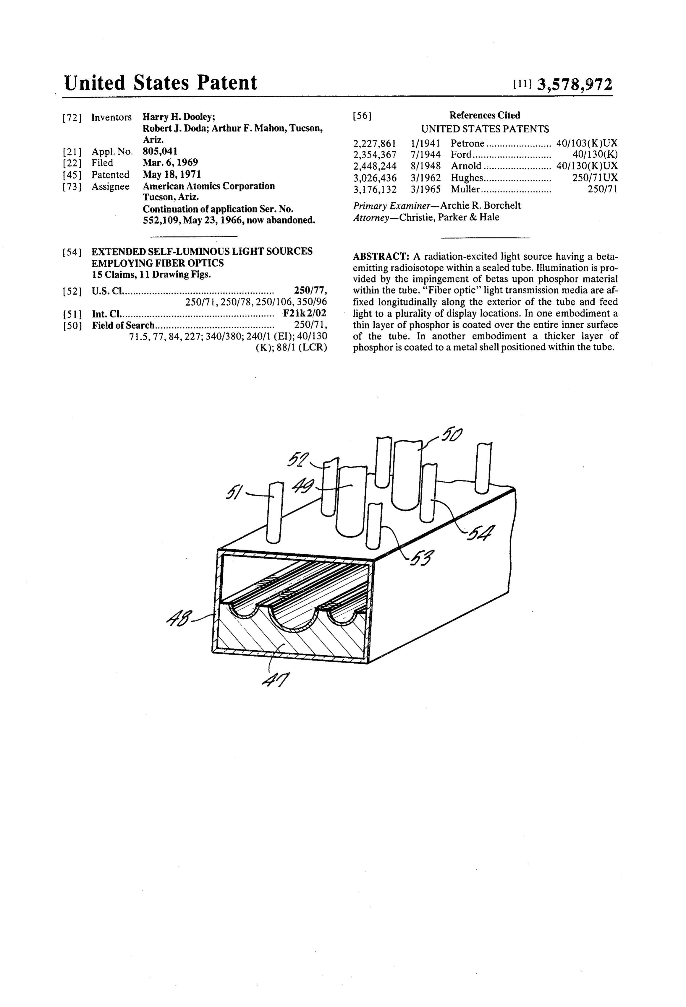
(54) EXTENDED SELF-LUMINOUSLIGHT SOURCES ABSTRACT: A radiation-excited light source having a beta EMPLOYING FIBER OPTICS emitting radioisotope within a sealed tube. Illumination is pro 15 Claims, 11 Drawing Figs. vided by the impingement of betas upon phosphor material 52 U.S. Cl........................................................ 250/77, within the tube. “Fiber optic' light transmission media areaf 250/71,250/78,250/106,350/96 fixed longitudinally along the exterior of the tube and feed
I51) Int. Cl......................................................... F21k2/02 light to a plurality of display locations. In one embodiment a 50 Field of Search............................................ 250/71, thin layer of phosphor is coated over the entire inner surface 71.5, 77, 84,227; 340/380; 240/1 (EI); 40/130 of the tube. In another embodiment a thicker layer of (K); 88/1 (LCR) phosphor is coated to a metal shell positioned within the tube.
Page 2
Drawing sheet — no readable text.
Page 3
Drawing sheet — no readable text.
Page 4
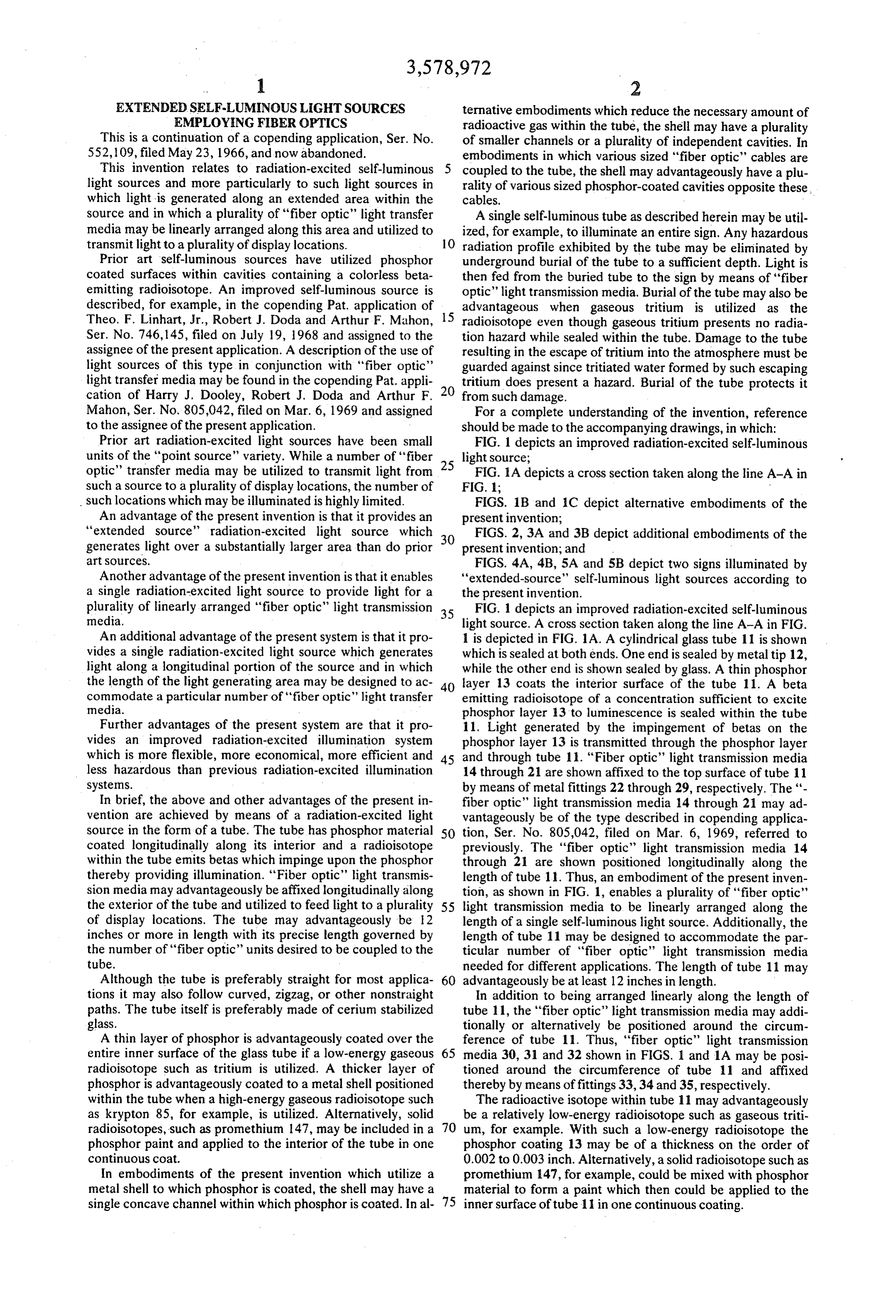
EXTENDED SELF-LUMINOUSLIGHT SOURCES ternative embodiments which reduce the necessary amount of EMPLOYING FIBER OPTICS radioactive gas within the tube, the shell may have a plurality This is a continuation of a copending application, Ser. No. of smaller channels or a plurality of independent cavities. In 552,109, filed May 23, 1966, and now abandoned. embodiments in which various sized "fiber optic' cables are This invention relates to radiation-excited self-luminous coupled to the tube, the shell may advantageously have a plu light sources and more particularly to such light sources in rality of various sized phosphor-coated cavities opposite these, which light is generated along an extended area within the cables.
source and in which a plurality of "fiber optic" light transfer A single self-luminous tube as described herein may be util media may be linearly arranged along this area and utilized to ized, for example, to illuminate an entire sign. Any hazardous transmit light to a plurality of display locations. 10 radiation profile exhibited by the tube may be eliminated by Prior art self-luminous sources have utilized phosphor underground burial of the tube to a sufficient depth. Light is coated surfaces within cavities containing a colorless beta then fed from the buried tube to the sign by means of "fiber emitting radioisotope. An improved self-luminous source is optic' light transmission media. Burial of the tube may also be described, for example, in the copending Pat. application of advantageous when gaseous tritium is utilized as the Theo. F. Linhart, Jr., Robert J. Doda and Arthur F. Mahon, 15 radioisotope even though gaseous tritium presents no radia Ser. No. 746,145, filed on July 19, 1968 and assigned to the tion hazard while sealed within the tube. Damage to the tube assignee of the present application. A description of the use of resulting in the escape of tritium into the atmosphere must be light sources of this type in conjunction with "fiber optic' guarded against since tritiated water formed by such escaping light transfer media may be found in the copending Pat. appli tritium does present a hazard. Burial of the tube protects it cation of Harry J. Dooley, Robert J. Doda and Arthur F. from such damage.
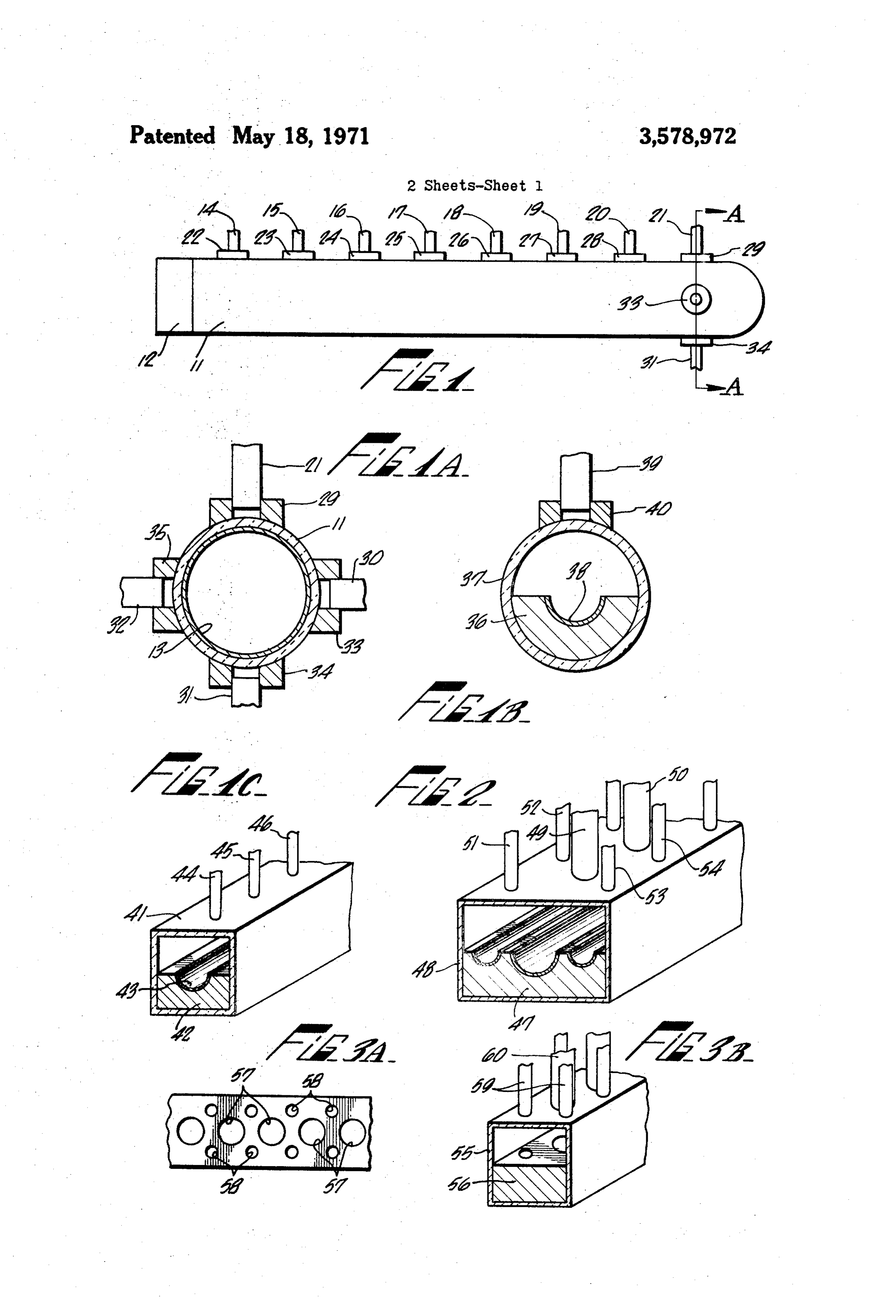
Mahon, Ser. No. 805,042, filed on Mar. 6, 1969 and assigned For a complete understanding of the invention, reference to the assignee of the present application. should be made to the accompanying drawings, in which: Prior art radiation-excited light sources have been small FIG. 1 depicts an improved radiation-excited self-luminous units of the "point source" variety. While a number of "fiber 25 light source;
optic' transfer media may be utilized to transmit light from FIG. A depicts a cross section taken along the line A-A in such a source to a plurality of display locations, the number of FIG. 1;
such locations which may be illuminated is highly limited. FIGS. 1B and 1C depict alternative embodiments of the An advantage of the present invention is that it provides an present invention;
“extended source' radiation-excited light source which FIGS. 2, 3A and 3B depict additional embodiments of the generates light over a substantially larger area than do prior present invention; and art sources. FIGS. 4A, 4B, 5A and 5B depict two signs illuminated by Another advantage of the present invention is that it enables "extended-source' self-luminous light sources according to a single radiation-excited light source to provide light for a the present invention.
plurality of linearly arranged "fiber optic" light transmission 35 FIG. 1 depicts an improved radiation-excited self-luminous media. light source. A cross section taken along the line A-A in FIG. An additional advantage of the present system is that it pro 1 is depicted in FIG. 1A. A cylindrical glass tube 11 is shown vides a single radiation-excited light source which generates which is sealed at both ends. One end is sealed by metal tip 12, light along a longitudinal portion of the source and in which while the other end is shown sealed by glass. A thin phosphor the length of the light generating area may be designed to ac 40 layer 13 coats the interior surface of the tube 11. A beta commodate a particular number of “fiber optic' light transfer emitting radioisotope of a concentration sufficient to excite media. phosphor layer 13 to luminescence is sealed within the tube Further advantages of the present system are that it pro 11, Light generated by the impingement of betas on the vides an improved radiation-excited illumination system phosphor layer 13 is transmitted through the phosphor layer which is more flexible, more economical, more efficient and 45 and through tube 11. "Fiber optic' light transmission media less hazardous than previous radiation-excited illumination 14 through 21 are shown affixed to the top surface of tube 11 systems. by means of metal fittings 22 through 29, respectively. The "- In brief, the above and other advantages of the present in fiber optic" light transmission media 14 through 21 may ad vention are achieved by means of a radiation-excited light vantageously be of the type described in copending applica source in the form of a tube. The tube has phosphor material 50 tion, Ser. No. 805,042, filed on Mar. 6, 1969, referred to coated longitudinally along its interior and a radioisotope previously. The "fiber optic” light transmission media 14 within the tube emits betas which impinge upon the phosphor through 21 are shown positioned longitudinally along the thereby providing illumination. “Fiber optic' light transmis length of tube 11. Thus, an embodiment of the present inven sion media may advantageously be affixed longitudinally along tion, as shown in FIG. 1, enables a plurality of "fiber optic' the exterior of the tube and utilized to feed light to a plurality 55 light transmission media to be linearly arranged along the of display locations. The tube may advantageously be 12 length of a single self-luminous light source. Additionally, the inches or more in length with its precise length governed by length of tube 11 may be designed to accommodate the par the number of “fiber optic' units desired to be coupled to the ticular number of "fiber optic' light transmission media tube. needed for different applications. The length of tube 11 may Although the tube is preferably straight for most applica 60 advantageously be at least 12 inches in length. tions it may also follow curved, zigzag, or other nonstraight In addition to being arranged linearly along the length of paths. The tube itself is preferably made of cerium stabilized tube 11, the "fiber optic' light transmission media may addi lass. tionally or alternatively be positioned around the circum 3. A thin layer of phosphor is advantageously coated over the ference of tube 11. Thus, "fiber optic' light transmission entire inner surface of the glass tube if a low-energy gaseous 65 media 30, 31 and 32 shown in FIGS. 1 and 1A may be posi radioisotope such as tritium is utilized. A thicker layer of tioned around the circumference of tube 11 and affixed phosphor is advantageously coated to a metal shell positioned thereby by means of fittings 33,34 and 35, respectively. within the tube when a high-energy gaseous radioisotope such The radioactive isotope within tube 11 may advantageously as krypton 85, for example, is utilized. Alternatively, solid be a relatively low-energy radioisotope such as gaseous triti radioisotopes, such as promethium 147, may be included in a 70 um, for example. With such a low-energy radioisotope the phosphor paint and applied to the interior of the tube in one phosphor coating 13 may be of a thickness on the order of continuous coat. 0.002 to 0.003 inch. Alternatively, a solid radioisotope such as In embodiments of the present invention which utilize a promethium 147, for example, could be mixed with phosphor metal shell to which phosphor is coated, the shell may have a material to form a paint which then could be applied to the single concave channel within which phosphor is coated. In al 75inner surface of tube 11 in one continuous coating.
Page 5
Should a relatively high-energy radioisotope such as kryp illustrative purposes, the space between shell 47 and the top of ton 85 be utilized, an embodiment such as that shown in FIG. tube 48 is shown to be somewhat larger than it would ordinari 1B is advantageous. FIG. 1B depicts a cross section of an em ly be. This space is made smaller than depicted in FIG. 2 in bodiment similar to that shown in FIGS. 1 and A. With order to reduce the quantity of radioisotope which must be respect to a high-energy radioisotope such as krypton 85, the sealed within the tube in order to excite the phosphor coating energy absorption of a phosphor coating as thin as that shown to luminescence.
in FIG. 1A is low and a thicker layer of phosphor is ad FIGS. 3A and 3B depict an embodiment of the present in vantageous in order to take full advantage of the radioisotope. vention in which further savings in the quantity of As the thickness of the phosphor layer increases, however, its radioisotope needed is achieved and in which a saving in the transparency decreases. Thus, if the thicker phosphor layer O quantity of phosphor material needed may also be realized. were coated over the entire inner surface of the glass tube, FIG. 3B depicts, in broken-away view, a glass tube 55 within only a relatively small amount of the light generated would which metal shell 56 is positioned. FIG. 3A depicts a broken pass entirely through the phosphor layer without being ab away top view of a portion of shell 56. Shell 56 has a plurality sorbed. In FIG. 1B, therefore, a metallic shell 36 is shown of individual cavities therein. A series of large cavities 57 are positioned within a glass tube 37. Shell 36 has a channel cut 15 arranged linearly along the center of shell 56 and a plurality of therein and a layer of phosphor 38 coats this channel. A smaller cavities 58 are arranged linearly along the two edges radioisotope such as krypton 85 is sealed within tube 37 and of shell 56. Each of the cavities 57 and 58 is coated with a impinges upon the phosphor coating 38, thereby exciting it to layer of phosphor material. Again, the space between shell 57 luminescence. A plurality of "fiber optic" light transmission 20 and the top of tube 55 is shown to be exaggerated for purposes media may be linearly arranged along the length of tuhe 37 and positioned opposite the channel in which phosphor layer of illustration. A radioisotope also sealed within tube 55 excites the phosphor within each of the cavities 57 and 58 to 38 is coated. One such 'fiber optic' media 39 affixed to tube luminescence. By providing individual cavities 57 and 58 37 by fitting 40 is shown in FIG. 1B. Tube 37 is ad rather than channels running along the entire length of shell vantageously made of cerium stabilized glass which is not ad 25 56, it is possible to reduce the amount of phosphor needed to versely affected by radiation.
When a radioisotope such as tritium or promethium i47 is coat the shell 56. Additionally, since the unfilled space within tube 55 is less when individual cavities rather than complete utilized, no radiation hazard is presented. When other channels are formed within shell 56, a smaller quantity of radioisotopes such as krypton 85, for example, are utilized, radioisotope however, there may be a radiation hazard developed. As tration of theisradioisotope. needed in order to achieve the desired concen “Fiber optic' light transfer media described in the copending application, Ser. No. 805,042, 30 of a first diameter 59 are coupled to the exterior of tube 55 op filed on Mar. 6, 1969, "fiber optic" light transfer media may posite each of the cavities 58. Similarly, "fiber optic" light be utilized to eliminate this radiation hazard by rendering shielding materials more effective and by transmitting light transfer media 60 are coupled to the exterior of tube 55 op from a location where such hazard exists to a location where 35 posite each of the cavities 57. As depicted in FIGS. 3A and no hazard exists. 3B, the ends of the transfer media 59 and 60 are in registration FIG. 1C depicts, in broken-away view, an embodiment of smaller with cavities 57 and 58, respectively. Again, for example, the the present invention similar to that shown in FIG. 1B. In FIG. media 59 may be 4-inch diameter "fiber optic' ca 1C a glass tube 41 having a rectangular cross section is shown bles, while the larger media 60 may be 2-inch "fiber optic' to have a metal shell 42 positioned therein. Shell 42 has a lon 40 cables.
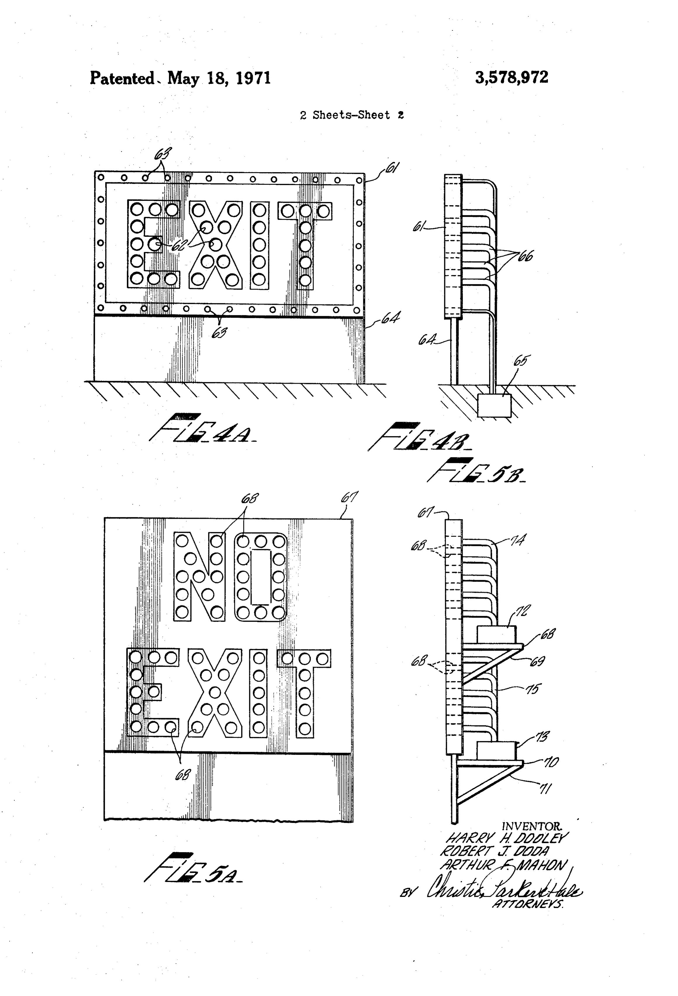
FIGS. 4A and 4B depict an illuminated sign utilizing "ex gitudinal channel cut therein which has a layer of phosphor tended-source' self-luminous tubes as described herein. FIG. material 43 coated thereon. Sealed within tube 41 is a radioisotope such as krypton 85 which is of a concentration 4A depicts a sign 61 on which the word EXIT appears. The sufficient to excite phosphor layer 43 to luminescence. Ar letters of this word are illuminated by light transmitted to dis ranged longitudinally along the length of tube 44 and affixed 45 play locations 62 within each letter. Additional display loca directly to tube 41 are "fiber optic' light transmission media tions 63 are located along the outer edges of sign 61. The dis 44, 45 and 46. Since tube 41 has a flat surface, the “fiber op play locations 62 are of a larger size than the display locations tic' media 44 through 46 may be affixed directly thereto 63 and may, for example, by one-half inch in diameter with lo rather than by means of fittings. The 'fiber optic' media 44 cations 63 being one-fourth inch in diameter. FIG. 4B depicts through 46 are affixed to tube 41 in positions directly opposite 50 a schematic side view of the sign shown in FIG. 4A. Sign 61 is the channel in shell 42 in which phosphor layer 43 is coated. shown supported above ground level by support means 64. A FIG. 2 depicts, also in broken-away view, an embodiment of tubular light source 65 such as that described herein is shown the present invention similar to that shown in FIG. C. In FIG. in FIG. 4B to be buried beneath the surface of the earth. '- 2, however, a metal shell 47 positioned within glass tube 48 Fiber optic' cables 66 transmit light generated by the buried has three channels therein; a large central channel and two 55 source 65 to the light display locations 62 and 63 on sign 61. smaller channels on opposite sides of the central channel and The entire sign 61 is thus illuminated as a result of light parallel to it. Each of these channels has a layer of phosphor generated by a single light source. The illumination of sign 61 material coated thereon. A radioactive isotope such as kryp is achieved more economically and more efficiently as a result ton 85, for example, is sealed within the tube 48 and excites of being illuminated by a single source. If source 65 utilizes a the phosphor coating in the channels to luminescence. “Fiber 60 radioisotope which presents a radiation hazard, the burial of optic' light transfer media 49 and 50 of a first diameter are af. the source may be utilized to eliminate this hazard. The earth fixed to the exterior of tube 48 opposite the central channel in surrounding source 65 then, effectively, provides a radiation shell 47. “Fiber optic" light transfer media 51 and 52 are af. shield. Alternatively, the source 65 may be enclosed in a lead fixed to the exterior of tube 48 opposite one of the smaller housing or other radiation shield material; it may also be both channels and "fiber optic' light transfer media 53 and 54 are 65 enclosed in a housing and buried. The ability of the "fiber op affixed to the exterior of tube 48 opposite the other of the two tic' light transfer media to permit transfer of light from the smaller channels. Light transfer media 51 through 54 are of a source to display locations, while at the same time permitting smaller diameter than media 49 and 50 and may ad the radiation shield material to completely surround the vantageously be used to transmit light to display locations radioisotope as described in the copending Pat. application, which are of a smaller size than those to which light is trans 70 Ser. No. 805,042, referred to previously, may also be utilized mitted by "fiber optic" media 49 and 50. The media 49 and 50 to achieve shielding in an embodiment similar to that shown in may, for example, be "fiber optic' cables of '4-inch diameter, FIGS. 4A and 4.B.
while transfer media 51 through 54 may, for example, be "- Besides eliminating any raiation hazard presented by the fiber optic' cables of 4-inch diameter. Such cables are radiation profile of source 6, burial of source 65 also serves presently available from E. I. DuPont De Nemours & Co. For 75 to protect it against any damage whereby a gaseous
Page 6
S 6 radioisotope may be allowed to escape from the sealed tube. 5. A self-luminous light source according to claim 4 in Thus, for example, although gaseous tritium does not present which the radioisotope is gaseous krypton 85. a hazardous radiation profile when within the sealed tube, it 6. A self-luminous light source according to claim 5 in does present a danger if allowed to escape into the at which the tube is made of cerium stabilized glass. mosphere. Tritium escaping into the atmosphere forms 7. A self-luminous light source according to claim 4 in tritiated water which can provide a hazard to human beings. which the shell has a first channel of a first width and a second Burial guards against such escape into the atmosphere. channel of a second width therein, each channel being FIGS.5A and 5B depict an alternative embodiment of an il disposed parallel to the longitudinal axis and having a layer of luminated sign. FIG. 5A depicts sign 67 on which the two phosphor material formed in it; in which one end of a first plu words NO EXIT appear with one word being positioned verti 10 rality of 'fiber optic' light transmission media of a first diame cally above the other. Each letter of the two words is illu ter are coupled to the tube and arranged along the tube op minated by means of light transmitted to a plurality of light posite the first channel in a row parallel to the longitudinal display locations 68. FIG. 5B depicts a broken-away side view axis; and in which one end of a second plurality of "fiber op of sign 67. As shown in FIG. 5B, a support member 68 is af. tic' light transmission media of a second diameter are coupled fixed to the rear of sign 67 by support strut 69 and a support 5 to the tube and arranged along the tube opposite the second member 70 is affixed to the rear of sign 67 by support strut 71. channel in a row parallel to the longitudinal axis. Self-luminous extended-sources 72 and 73, of the type 8. An illuminated sign comprising: described herein, are positioned on support members 68 and a display member having a first plurality of display locations 70, respectively. "Fiber optic' light transfer cables 74 trans thereon, the display locations being arranged in a com mit light from source 72 to the display locations of the upper 20 mon plane to form at least one informational character; word appearing on sign 67 and 'fiber optic' light transfer ca an elongated light transmissive tube sealed at both ends, the bles 75 transmit light generated by source 73 to the display lo tube being disposed on a longitudinal axis parallel to the cations of the lower word appearing on sign 67. In the embodi common plane;
ment shown in FIGS. 5A and 5B, a separate extended-source a layer of phosphor material formed within the tube; self-luminous tube is utilized for the illumination of each 25 a radioactive particle emitting material within the tube, the horizontal row of characters appearing on a sign. By using a quantity of the radioactive material being sufficient to separate light source for each row of characters, the light excite the phosphor to luminescence; and source illuminating a particular row may be affixed to the rear a first plurality of "fiber optic' light transmission means for of the sign in close proximity to the row of characters it illu 30 transmitting light by substantially total internal reflection, minates. Consequently, fairly short "fiber optic' cables may one end of the first plurality of light transmission means be utilized to transmit light from the source to the row being il being connected to the tube and positioned along the luminated by that source. Since lengthy "fiber optic' cables tube in a row parallel to the longitudinal axis, the other are not needed, a high efficiency of light transfer from the end of the first plurality of light transmission means being source to the illuminated characters is achieved. 35 coupled to different ones of the first plurality of display The embodiments which have been described are con locations for transmitting light from the tube to respective sidered to be illustrative of the present invention. Ac ones of the first plurality of display locations. cordingly, it is to be understood that various and numerous 9. An illuminated sign according to claim 8 in which the other arrangements may be devices by one skilled in the art tube is buried beneath the surface of the earth. without departing from the spirit and scope of this invention. 40 10. An illuminated sign according to claim 8 in which the
display member has a second plurality of display locations 1. A self-luminous light source comprising: thereon, each of the first plurality of display locations being of a translucent, elongated cylindrical tube sealed at both a particular first size and each of the second plurality of dis ends, the tube being disposed on a longitudinal axis; play locations being of a particular second size, and further a layer of phosphor material coated over substantially all of 45 comprising:
the interior surface of the tube; a second plurality of "fiber optic' light transmission means a beta-emitting radioisotope within the tube, the quantity of for transmitting light by substantially total internal reflec the radioisotope being sufficient to excite the phosphor to tion, one end of the second plurality of light transmission luminescence; and means being connected to the tube, the other end of the a plurality of “fiber optic' light transmission media for 50 second plurality of light transmission means being con transmitting light by substantially total internal reflection, nected to different ones of the second plurality of display one end of the media being connected to the tube and locations for transmitting light from the tube to respective positioned along the tube in a row parallel to the longitu ones of the second plurality of display locations, each of dinal axis. the first plurality of "fiber optic" means being of a par 2. A self-luminous light source according to claim 1 further 55 ticular first size and each of the second plurality of "fiber comprising a plurality of "fiber optic' light transmission optic' means being of a particular second size. media connected to the tube and positioned circumferentially 11. An illuminated sign according to claim 10 in which the around the tube. display locations of the second plurality of locations are posi 3. A self-luminous light source according to claim 1 in tioned near the periphery of the display member. which the radioisotope is gaseous tritium. 60 12. An illuminated sign comprising: 4. A self-luminous light source comprising: a display member having a first plurality of display locations an elongated light transmissive tube sealed at both ends, the positioned on the face thereof and arranged to form at tube being disposed on a longitudinal axis; least one informational character; a shell positioned within the tube and having at least one the display member having a second plurality of display lo elongated channel parallel to the longitudinal axis; 65 cations positioned on the face thereof and arranged to a layer of phosphor material formed on the surface of the form at least one informational character; channel; the second plurality of display locations positioned above a radioactive particle emitting material within the tube, the the first plurality of display locations; quantity of the radioactive material being sufficient to first and second support members affixed to the rear of the excite the phosphor to luminescence, and 70 display member, the second support member being posi a plurality of "fiber optic' light transmission media for tioned above the first support member; transmitting light by substantially total internal reflection, first and second translucent tubes positioned on the first and one end of the media being coupled to the tube and posi second support members, respectively; tioned opposite the channel in a row parallel to the lon each tube being sealed at both ends and having a layer of gitudinal axis. 75 phosphor material and a beta emitting radioisotope
Page 7
within the tube, the quantity of the radioisotope being luminescence; and sufficient to excite the phosphor to luminescence; a plurality of elongated, light transmissive tubes, one end of a first plurality of "fiber optic' light transmission media for the tubes being arranged on the exterior of the enclosure transmitting light by substantially total internal reflection, in a row along the longitudinal axis so light emanating one end of the light transmission media being connected 5 from the enclosure is coupled to the tubes. to the first tube and positioned in a row longitudinally 14. The light source of claim 13, in which the other end of along the tube, the other end of the light transmission the tubes is arranged in a plane substantially removed from media being connected to respective ones of the first plu and parallel to the longitudinal axis. rality of display locations for transmitting light from the 15. A self-luminous light source comprising: first tube to the first plurality of display locations; and O an elongated, light transmissive, sealed enclosure, the en a second plurality of 'fiber optic' light transmission media closure being disposed along a longitudinal axis; for transmitting light by substantially total internal reflec a shell positioned within the enclosure and having a plurali tion, one end of the light transmission media being con ty of individual cavities arranged in a row parallel to the nected to the second tube and positioned in a row longitu longitudinal axis;
dinally along the tube, the other end of the light transmis 5 a layer of phosphor material formed on the surfaces of the sion media being connected to respective ones of the cavities;
second plurality of display locations for transmitting light a radioactive particle emitting material within the enclo from the second tube to the second plurality of display lo sure, the quantity of the radioactive material being suffi cations, cient to excite the phosphor to luminescence; and 13. A self-luminous light source comprising: 20 a plurality of 'fiber optic' light transmission media for an elongated, light transmissive enclosure disposed on a lon transmitting light by substantially total internal reflection, gitudinal axis, one end of the media being coupled to the enclosure and a material forming a phosphor surface within the enclosure; positioned opposite the cavities in a row parallel to the a radioactive particle emitting material within the enclo 25 longitudinal axis and in registration with the respective sure, the quantity of the radioactive particle emitting cavities.
material being sufficient to excite the phosphor surface to
Provenance
- Collection
- Cited prior art
- Original PDF
- patentimages.storage.googleapis.com →
- Filed
- 1969-03-06
- Pages
- 7
- Method
- pdftotext (the PDF's own text layer) + pdftoppm 300dpi page scans
- Source
- Google Patents bibliographic record
- Granted
- 1971-05-18
- Inventors
- Harry H Dooley; Robert J Doda; Arthur F Mahon; American Atomics Corp
- Transcribed from
- patentimages.storage.googleapis.com →