patent · US3532550
Fuel cell with alternately folded sheet electrode
6 October 1970
Page 1
Drawing sheet — no readable text.
Page 2
Drawing sheet — no readable text.
Page 3
Drawing sheet — no readable text.
Page 4
United States Patent Office Patented (Oct. 6, 1970
of when read in conjunction with the appended claims 3,532,550 and attached drawings wherein:
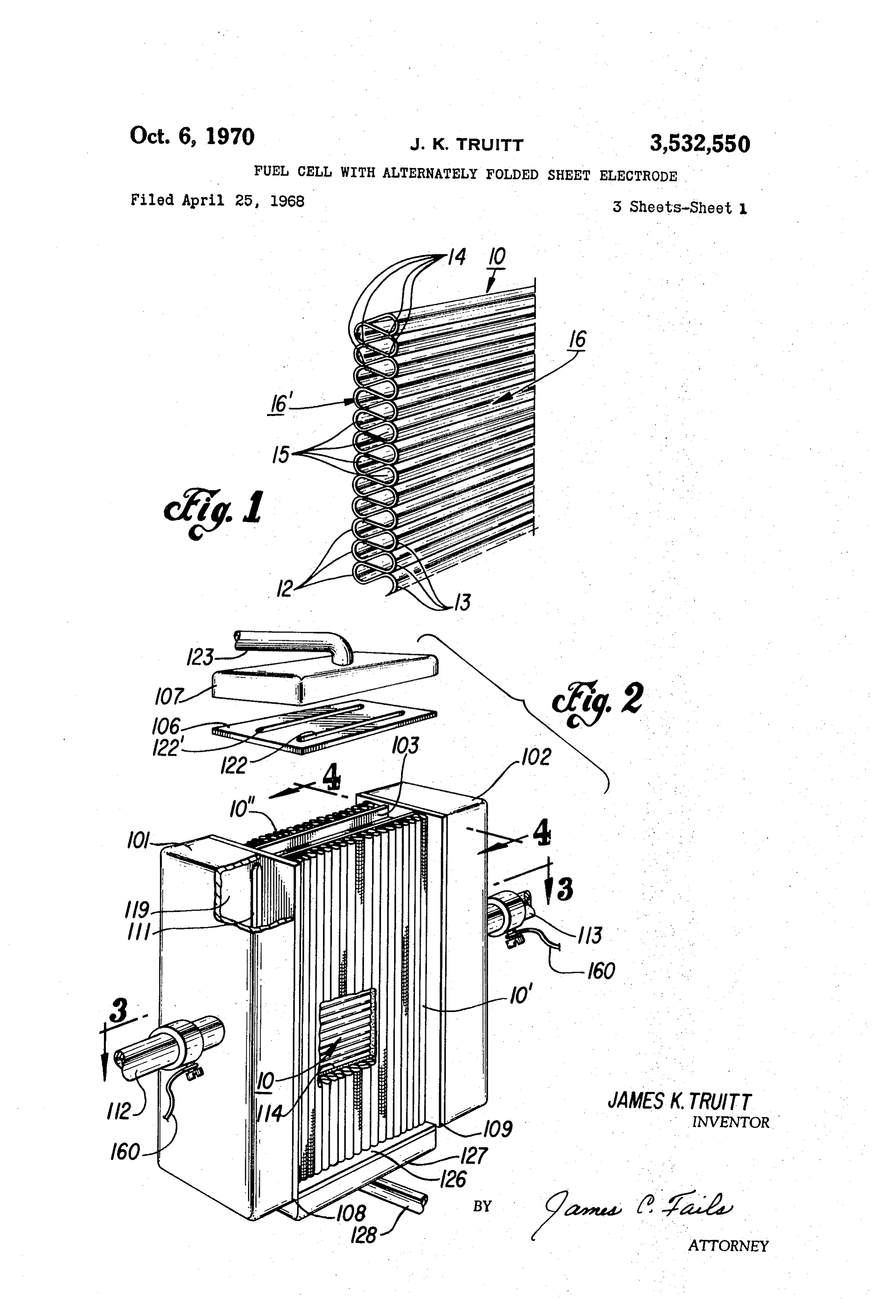
FUEL CELL WITH ALTERNATELY FOLDED FIG. 1 is a perspective view of a preferred embodiment
SHEET EECTRODE
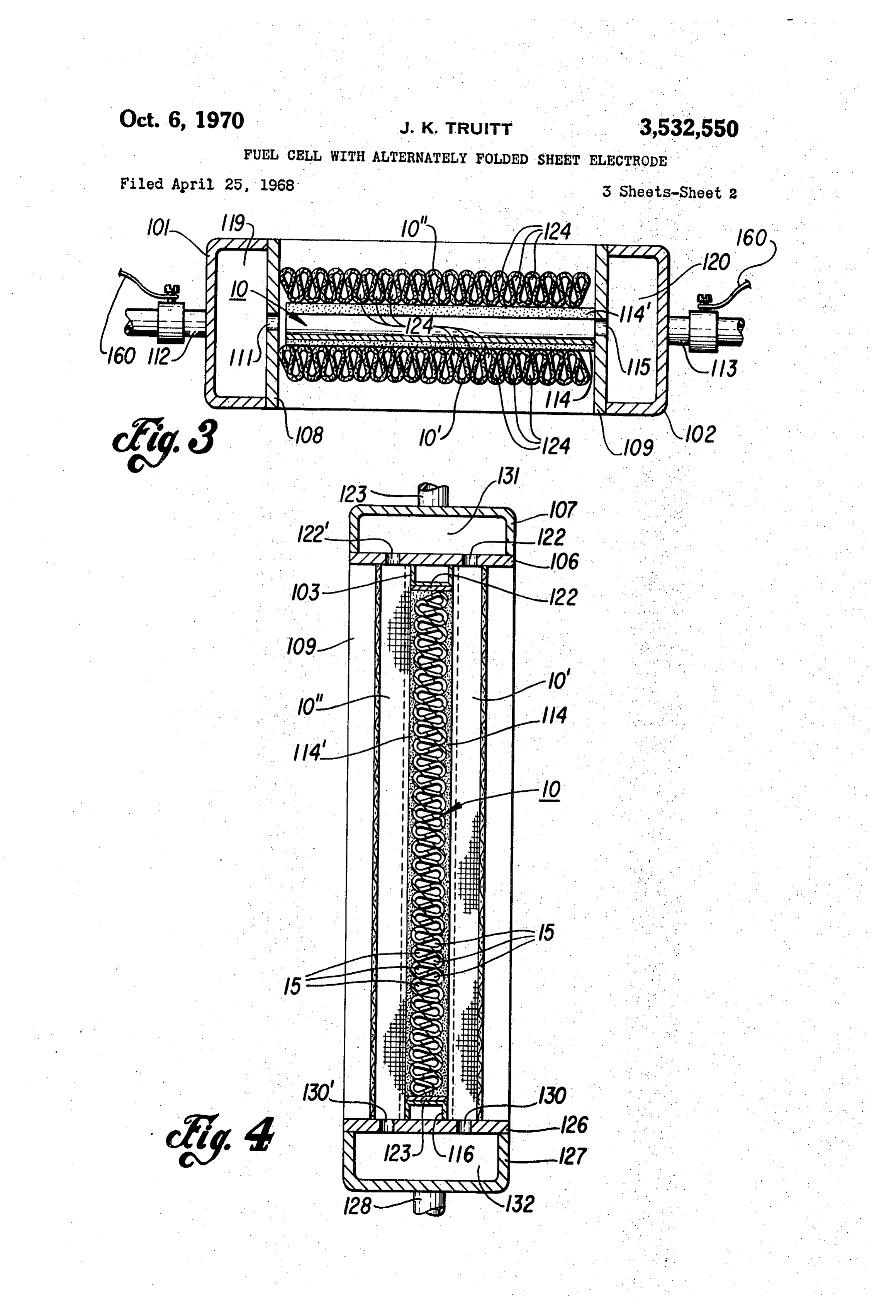
James K. Truitt, Dallas, Tex., assignor to Texas Instru of the electrode of the invention; ments incorporated, Dallas, Tex., a corporation of FIG. 2 is a perspective view of a structure containing Delaware two fuel cells which embody the electrode of the inven Filed Apr. 25, 1968, Ser. No. 724,097 tion. A small portion is cut away to show a part of the Int, C. HOn 27/00 interior construction, while the two top cover elements U.S. C. 136-86 9 Claims of the cell structure are lifted and separated from each O other and from the cell body to show their relation to one another;
ABSTRACT OF THE DISCLOSURE FIG. 3 is a cross-sectional view of the structure of A fuel cell is disclosed having electrodes each of a single FIG. 2, taken along line 3-3 of FIG. 2; and FIG. 4 is a cross-sectional view of the structure of FIG.
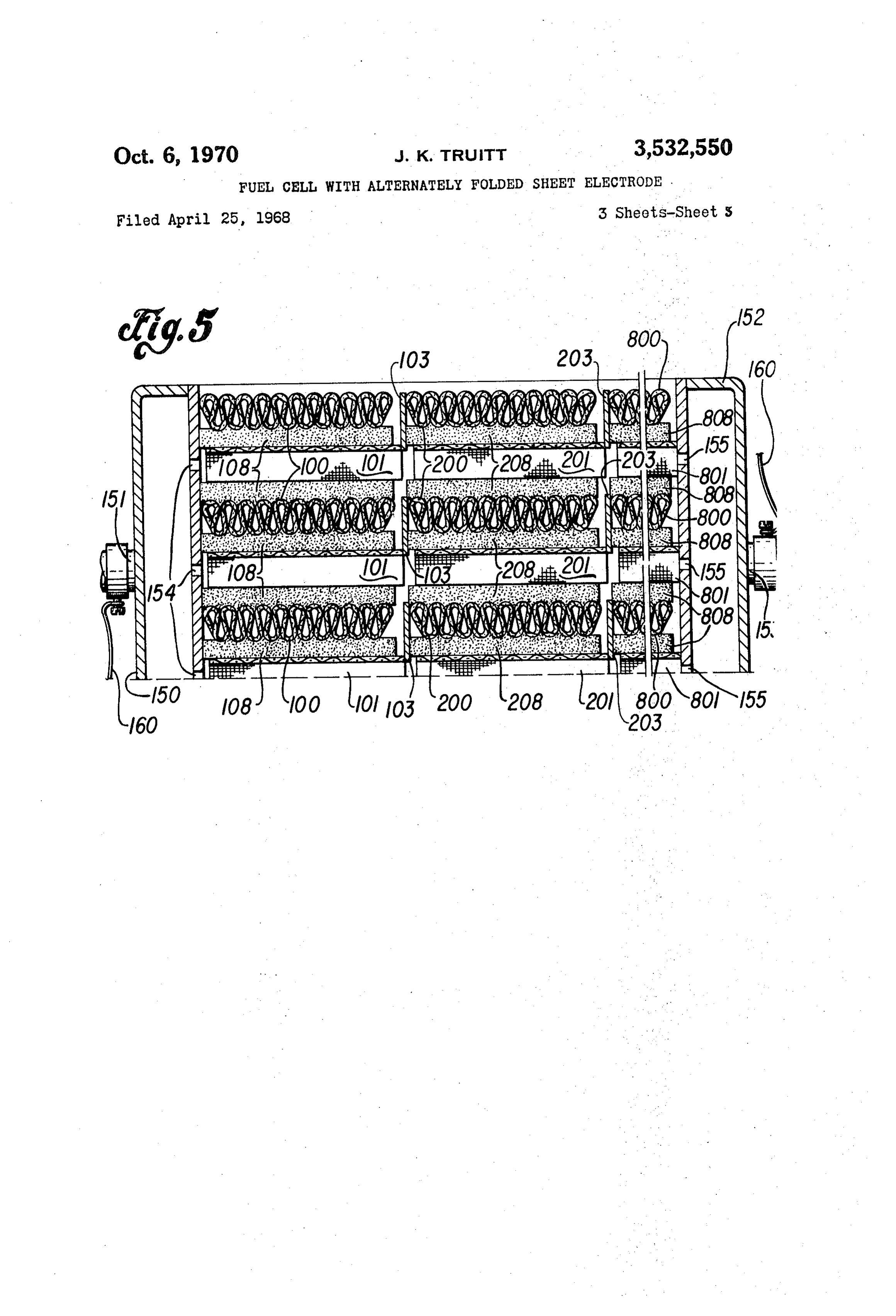
metal sheet or of a single metal screen formed into a 2, taken along line 4-4 of FIG. 2. series of tear-drop shaped folds which for any given FIG. 5 is a top view of a portion of a multicell power cell space increase the reaction area of reactant and elec package incorporating fuel cells interconnected in series trolyte upon the surface of the electrode. and a number of fuel cells interconnected in parallel, em assassissix-streamww. bodying the electrode of the invention.
20 The figures in the drawings are not to scale, the dimen
This invention relates to improvements in electrodes for sions being exaggerated to better illustrate the construc use in fuel cells and the like. tion and manner of operation of the invention. The development of fuel cells for powering automo Referring now to the drawings, and particularly to biles, trucks, Satellites, or space stations, for example, is FEG. 1, the electrode of the invention, generally indi becoming of increasing importance. To fill the vigorous cated by the numeral 10, may be made, for example, of demands of such possible uses, highly efficient multicell a solid metal sheet (Subject to a qualification noted here power packages of compact size and high power densities inafter) or a metal screen. As a multiplicity of electrically will be required. conducting materials can be used, the material of con Presently used fuel cells generally comprise two elec struction is not intended to be a limitation on the inven trodes (a cathode and an anode) separated by an elec tion. Examples of suitable electrode materials are silver, trolyte. At each electrode, a partial chemical reaction nickel, iron, stainless steel, silver-coated stainless steel, occurs: between reductant and electrolyte on one elec and nickel-impregnated stainless steel. trode and between oxidizer and electrolyte on the other, The sheet (or screen), alternately folded at such points creating an electric potential difference between the elec as 12 and 13 SO as to form a continuously pleated, or trodes, and, of course, furnishing electrical power. Serpentine, or alternating-tear-drop shaped pattern, is held The power density, the power output per unit of cell in the indicated shape by brazing or spot welding points volume, is determined, in part, by the extent of the con of contact, Such as those illustrated by the numeral 14. tact between the reactant, air (oxidizer) or fuel (reduc This folded pattern allows reactants to freely flow through tant), and the electrolyte. This contact is obviously in the spaces 15, and the electrolyte to contact the areas gen creased as the reaction area of the electrodes in the re 40 erally indicated by the numerals 16 and 16. actant streams in increased. One requirement of an ideal The electrode of the invention, compared to previously electrode, therefore, is that its reaction area be made as proposed electrodes, for any given cell size presents a large as possible. In the prior art, one attempt to satisfy greatly increased reaction surface area which may have, this requirement has been to use a plurality of intercon for example, in excess of 10 times the amount of elec nected electrode elements; this attempt, however, was trode material than previous designs, vastly increasing the not wholly successful because the size of the cell became probability of reactant and electrolyte contact and, there unduly large in relation to its power density. fore, resulting in greater obtainable power densities. More In addition to power density, the overall efficiency of over, flooding and eventual polarization of the electrode the cell must be considered in fuel cell design. Effi are virtually eliminated. If the electrode is made of screen ciency is affected, in part, by such factors as the internal material, the vast number of “pores' because of and resistance of the cell, the amount of contamination of throughout its length makes flooding (and therefore the fuel, the availability of reactants at the reaction areas, polarization) virtually impossible. And if the electrode and the adverse effect of cell “flooding,' a condition which consists of a solid metal sheet, flooding is actually impos occurs when the electrode pores become so saturated with sible since there are no pores to flood. electrolyte that the reaction occurs on an electrolyte film While the electrode of the invention is suitable for use above the electrode such that the potential of the reac either as the fuel or reducing electrode (anode), or the tion cannot be removed to the external circuit. Electrode air or oxidizing electrode (cathode), it is particularly use flooding leads to undesirable cell polarization and reduced ful as a fuel electrode in cells using hydrogen as the fuel. efficiency. Although the exact operation of the electrode in the It is therefore an object of the invention to provide an 60 latter case is not understood, it appears that the hydrogen electrode which virtually maximizes the reaction area fuel is adsorbed by the electrode material and carried per unit of cell volume thereby increasing power density directly to the electrolyte for reaction therewith, rather and efficiency and decreasing the probability of flooding. than reacting with the electrolyte at the location on the Another object of the invention is to provide a multi electrode surface with which the reactant is caused to first cell power package structure of improved design having a 65 contact. It can be appreciated that this phenomenon plurality of fuel cells interconnected in series together would, in itself, reduce the possibility of cell polarization, with a plurality of fuel cells connected in parallel, all since the reaction of hydrogen with electrolyte is from of the fuel cells utilizing the improved electrode of the the "inside' of the electrolyte coat on the electrode sur invention. face rather than above the electrode as above described Other objects, features and advantages of the invention 70 in connection with electrode flooding. Hence, even if the will become apparent to those skilled in the art from the electrode of the invention does become flooded in certain following detailed description of one embodiment there of its areas, a partial reaction could still occur because
Page 5
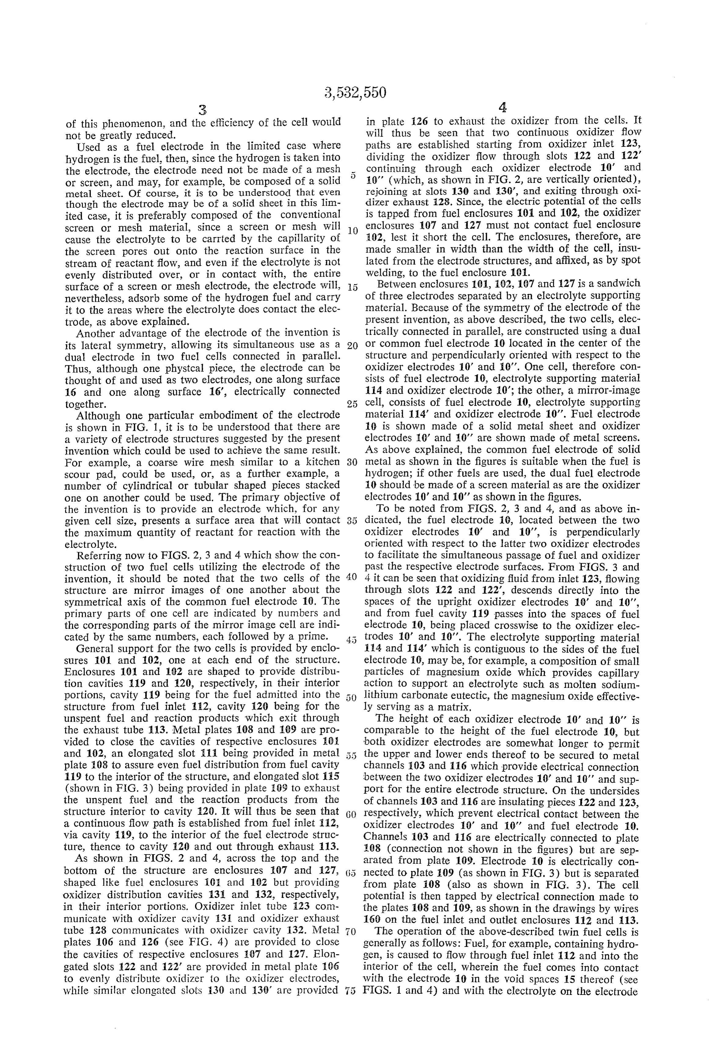
of this phenomenon, and the efficiency of the cell would in plate 126 to exhaust the oxidizer from the cells. It not be greatly reduced. will thus be seen that two continuous oxidizer flow Used as a fuel electrode in the limited case where paths are established starting from oxidizer inlet 123, hydrogen is the fuel, then, since the hydrogen is taken into dividing the oxidizer flow through slots 122 and 122' the electrode, the electrode need not be made of a mesh 5 continuing through each oxidizer electrode 10' and or screen, and may, for example, be composed of a solid i0' (which, as shown in FIG. 2, are vertically oriented), metal sheet. Of course, it is to be understood that even rejoining at slots 130 and 30', and exiting through oxi though the electrode may be of a solid sheet in this lim dizer exhaust 28. Since, the electric potential of the cells ited case, it is preferably composed of the conventional is tapped from fuel enclosures 10 and 102, the oxidizer screen or mesh material, since a screen or mesh will O enclosures 107 and 127 must not contact fuel enclosure cause the electrolyte to be carrted by the capillarity of :02, lest it short the cell. The enclosures, therefore, are the screen pores out onto the reaction surface in the made smaller in width than the width of the cell, insu stream of reactant flow, and even if the electrolyte is not lated from the electrode structures, and affixed, as by spot evenly distributed over, or in contact with, the entire welding, to the fuel enclosure 101. surface of a screen or mesh electrode, the electrode will, 5 Between enclosures 101, 92, 107 and 127 is a sandwich nevertheless, adsorb some of the hydrogen fuel and carry of three electrodes separated by an electrolyte supporting it to the areas where the electrolyte does contact the elec material. Because of the symmetry of the electrode of the trode, as above explained. present invention, as above described, the two cells, elec Another advantage of the electrode of the invention is trically connected in parallel, are constructed using a dual its lateral symmetry, allowing its simultaneous use as a 20 or common fuel electrode 0 located in the center of the dual electrode in two fuel cells connected in parallel. Structure and perpendicularly oriented with respect to the Thus, although one phystcal piece, the electrode can be Oxidizer electrodes 10' and 0'. One cell, therefore con thought of and used as two electrodes, one along surface sists of fuel electrode 10, electrolyte supporting material 16 and one along surface 16, electrically connected i4 and oxidizer electrode 0; the other, a mirror-image together. 25 cell, consists of fuel electrode 10, electrolyte supporting Although one particular embodiment of the electrode material 114' and oxidizer electrode 10'. Fuel electrode is shown in FIG. 1, it is to be understood that there are 10 is shown made of a solid metal sheet and oxidizer a variety of electrode structures suggested by the present electrodes 10' and 10' are shown made of metal screens. invention which could be used to achieve the same result. As above explained, the common fuel electrode of solid For example, a coarse wire mesh similar to a kitchen 30 metal as shown in the figures is suitable when the fuel is scour pad, could be used, or, as a further example, a hydrogen; if other fuels are used, the dual fuel electrode number of cylindrical or tubular shaped pieces stacked 10 should be made of a screen material as are the oxidizer one on another could be used. The primary objective of electrodes 10' and 10' as shown in the figures. the invention is to provide an electrode which, for any To be noted from FIGS. 2, 3 and 4, and as above in given cell size, presents a surface area that will contact 3 5 dicated, the fuel electrode 10, located between the two the maximum quantity of reactant for reaction with the oxidizer electrodes 10' and 10", is perpendicularly electrolyte. oriented with respect to the latter two oxidizer electrodes Referring now to FIGS. 2, 3 and 4 which show the con to facilitate the simultaneous passage of fuel and oxidizer struction of two fuel cells utilizing the electrode of the past the respective electrode surfaces. From FIGS. 3 and invention, it should be noted that the two cells of the 40 4 it can be seen that oxidizing fluid from inlet 123, flowing structure are mirror images of one another about the through slots 122 and 122, descends directly into the symmetrical axis of the common fuel electrode 10. The Spaces of the upright oxidizer electrodes 10 and 10', primary parts of one cell are indicated by numbers and and from fuel cavity 119 passes into the spaces of fuel the corresponding parts of the mirror image cell are indi electrode 10, being placed crosswise to the oxidizer elec cated by the same numbers, each followed by a prime. trodes 10 and 10'. The electrolyte supporting material General support for the two cells is provided by enclo 114 and 114" which is contiguous to the sides of the fuel Sures 101 and 102, one at each end of the structure. electrode 10, may be, for example, a composition of small Enclosures 101 and 102 are shaped to provide distribu particles of magnesium oxide which provides capillary tion cavities 19 and 120, respectively, in their interior action to Support an electrolyte such as molten sodium portions, cavity 119 being for the fuel admitted into the lithium carbonate eutectic, the magnesium oxide effective structure from fuel inlet 112, cavity 120 being for the ly serving as a matrix.
unspent fuel and reaction products which exit through The height of each oxidizer electrode 10' and 10' is the exhaust tube 113. Metal plates 108 and 109 are pro comparable to the height of the fuel electrode 10, but vided to close the cavities of respective enclosures 10 both oxidizer electrodes are somewhat longer to permit and 102, an elongated slot 111 being provided in metal 5 5 the upper and lower ends thereof to be secured to metal plate 208 to assure even fuel distribution from fuel cavity channels 103 and 116 which provide electrical connection 119 to the interior of the structure, and elongated slot 115 between the two oxidizer electrodes 10' and 10' and Sup (shown in FIG. 3) being provided in plate 109 to exhaust Port for the entire electrode structure. On the undersides the unspent fuel and the reaction products from the of channels 103 and 116 are insulating pieces 122 and 123, Structure interior to cavity 120. It will thus be seen that GO) respectively, which prevent electrical contact between the a continuous flow path is established from fuel inlet 112, oxidizer electrodes 10' and 10' and fuel electrode 10. via cavity 119, to the interior of the fuel electrode struc Channels 103 and 116 are electrically connected to plate ture, thence to cavity 120 and out through exhaust 113. 108 (connection not shown in the figures) but are sep As shown in FIGS. 2 and 4, across the top and the arated from plate 109. Electrode 10 is electrically con bottom of the structure are enclosures 107 and 127, nected to plate 109 (as shown in FIG. 3) but is Separated shaped like fuel enclosures 101 and 102 but providing from plate 108 (also as shown in FIG. 3). The cell oxidizer distribution cavities 131 and 132, respectively, potential is then tapped by electrical connection made to in their interior portions. Oxidizer inlet tube 23 com the plates 108 and 109, as shown in the drawings by wires municate with oxidizer cavity 3 and oxidizer exhaust 160 on the fuel inlet and outlet enclosures 112 and 13. tube 128 communicates with oxidizer cavity 132. Metal The operation of the above-described twin fuel cells is plates 106 and 126 (see FIG. 4) are provided to close generally as follows: Fuel, for example, containing hydro the cavities of respective enclosures 107 and 127. Elon gen, is caused to flow through fuel inlet 112 and into the gated slots 122 and 22' are provided in metal plate 106 interior of the cell, wherein the fuel comes into contact to evenly distribute oxidizer to the oxidizer electrodes, with the electrode 10 in the void spaces 15 thereof (see while similar elongated slots 130 and 130 are provided 5 FIGS. 1 and 4) and with the electrolyte on the electrode
Page 6
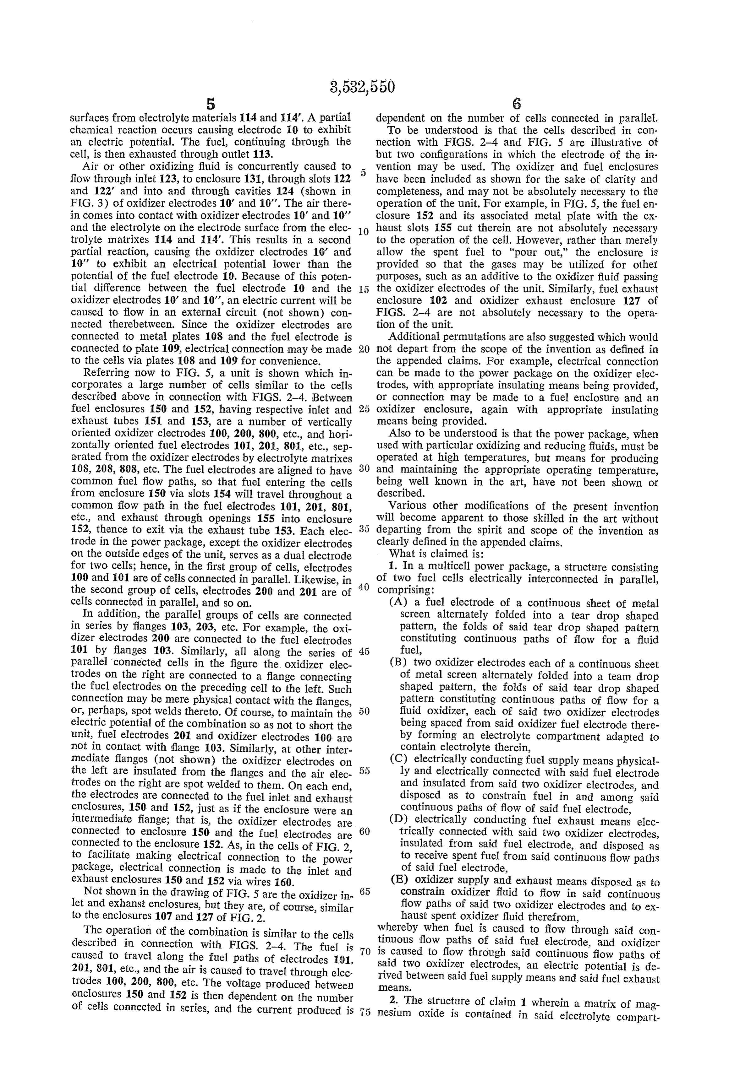
surfaces from electrolyte materials 114 and 14. A partial dependent on the number of cells connected in parallel. chemical reaction occurs causing electrode 10 to exhibit To be understood is that the cells described in con an electric potential. The fuel, continuing through the nection with FIGS. 2-4 and FIG. 5 are illustrative of cell, is then exhausted through outlet 113. but two configurations in which the electrode of the in Air or other oxidizing fluid is concurrently caused to 5 vention may be used. The oxidizer and fuel enclosures flow through inlet 123, to enclosure 131, through slots 122 have been included as shown for the sake of clarity and and 122 and into and through cavities 124 (shown in completeness, and may not be absolutely necessary to the FIG. 3) of oxidizer electrodes 10' and 10'. The air there operation of the unit. For example, in FIG. 5, the fuel en in comes into contact with oxidizer electrodes 10' and 10' closure 152 and its associated metal plate with the ex and the electrolyte on the electrode surface from the elec O haust slots 155 cut therein are not absolutely necessary trolyte matrixes 114 and 114'. This results in a second to the operation of the cell. However, rather than merely partial reaction, causing the oxidizer electrodes 10' and allow the spent fuel to "pour out,' the enclosure is 10' to exhibit an electrical potential lower than the provided so that the gases may be utilized for other potential of the fuel electrode 10. Because of this poten purposes, such as an additive to the oxidizer fluid passing tial difference between the fuel electrode 10 and the the oxidizer electrodes of the unit. Similarly, fuel exhaust oxidizer electrodes 10' and 10', an electric current will be enclosure 102 and oxidizer exhaust enclosure 27 of caused to flow in an external circuit (not shown) con FIGS. 2-4 are not absolutely necessary to the opera nected therebetween. Since the oxidizer electrodes are tion of the unit.
connected to metal plates 108 and the fuel electrode is Additional permutations are also suggested which would connected to plate 109, electrical connection may be made 20 not depart from the scope of the invention as defined in to the cells via plates 108 and 109 for convenience. the appended claims. For example, electrical connection Referring now to FIG. 5, a unit is shown which in can be made to the power package on the oxidizer elec corporates a large number of cells similar to the cells trodes, with appropriate insulating means being provided, described above in connection with FIGS. 2-4. Between or connection may be made to a fuel enclosure and an fuel enclosures 150 and 152, having respective inlet and 25 Oxidizer enclosure, again with appropriate insulating exhaust tubes 151 and 153, are a number of vertically means being provided.
oriented oxidizer electrodes 100, 200, 800, etc., and hori Also to be understood is that the power package, when Zontally oriented fuel electrodes 101, 2011, 801, etc., sep used with particular oxidizing and reducing fluids, must be arated from the oxidizer electrodes by electrolyte matrixes operated at high temperatures, but means for producing 108, 208, 808, etc. The fuel electrodes are aligned to have and maintaining the appropriate operating temperature, common fuel flow paths, so that fuel entering the cells being Well known in the art, have not been shown or from enclosure 150 via slots 154 will travel throughout a described.
common flow path in the fuel electrodes 101, 201, 801, Various other modifications of the present invention etc., and exhaust through openings 155 into enclosure Will become apparent to those skilled in the art without 152, thence to exit via the exhaust tube 153. Each elec departing from the Spirit and scope of the invention as trode in the power package, except the oxidizer electrodes clearly defined in the appended claims. on the outside edges of the unit, serves as a dual electrode What is claimed is:
for two cells; hence, in the first group of cells, electrodes 1. In a multicell power package, a structure consisting 100 and 101 are of cells connected in parallel. Likewise, in 40 of two fuel cells electrically interconnected in parallel, the Second group of cells, electrodes 200 and 201 are of comprising:
cells connected in parallel, and so on. (A) a fuel electrode of a continuous sheet of metal In addition, the parallel groups of cells are connected Screen alternately folded into a tear drop shaped in Series by flanges 103, 203, etc. For example, the oxi pattern, the folds of said tear drop shaped pattern dizer electrodes 200 are connected to the fuel electrodes constituting continuous paths of flow for a fluid 101 by flanges 103. Similarly, all along the series of fuel,
Parallel connected cells in the figure the oxidizer elec (B) two oxidizer electrodes each of a continuous sheet trodes on the right are connected to a flange connecting of metal Screen alternately folded into a team drop the fuel electrodes on the preceding cell to the left. Such shaped pattern, the folds of said tear drop shaped connection may be mere physical contact with the flanges, pattern constituting continuous paths of flow for a or, perhaps, spot welds thereto. Of course, to maintain the fluid oxidizer, each of said two oxidizer electrodes electric potential of the combination so as not to short the being Spaced from Said oxidizer fuel electrode there unit, fuel electrodes 201 and oxidizer electrodes 100 are by forming an electrolyte compartment adapted to not in contact with flange 103. Similarly, at other inter contain electrolyte therein, mediate flanges (not shown) the oxidizer electrodes on (C) electrically conducting fuel supply means physical the left are insulated from the flanges and the air elec ly and electrically connected with said fuel electrode trodes on the right are spot welded to them. On each end, and insulated from said two oxidizer electrodes, and the electrodes are connected to the fuel inlet and exhaust disposed as to constrain fuel in and among said enclosures, 150 and 152, just as if the enclosure Were an continuous paths of flow of said fuel electrode, intermediate flange; that is, the oxidizer electrodes are (D) electrically conducting fuel exhaust means elec connected to enclosure 150 and the fuel electrodes are 60 trically connected with said two oxidizer electrodes, Connected to the enclosure 152. As, in the cells of FIG. 2, insulated from said fuel electrode, and disposed as to facilitate making electrical connection to the power to receive spent fuel from said continuous flow paths package, electrical connection is made to the inlet and of said fuel electrode, exhaust enclosures 150 and 152 via wires 160. (E) oxidizer Supply and exhaust means disposed as to Not shown in the drawing of FIG. 5 are the oxidizer in 65 constrain oxidizer fluid to flow in said continuous let and exhanst enclosures, but they are, of course, similar flow paths of Said two oxidizer electrodes and to ex to the enclosures 107 and 127 of FiG 2 haust spent oxidizer fluid therefrom, The operation of the combination is similar to the cells whereby when fuel is caused to flow through said con described in connection with FIGS. 2-4. The fuel is 70 istinuous flow paths of said fuel electrode, and oxidizer caused to flow through said continuous flow paths of caused to travel along the fuel paths of electrodes 10, 201, 801, etc., and the air is caused to travel through elec Said two oxidizer electrodes, an electric potential is de rived between said fuel Supply means and said fuel exhaust trodes 100, 200, 800, etc. The Voltage produced between CaS enclosures 150 and 152 is then dependent on the number of cells connected in Series, and the current produced is 2. The structure of claim 1 wherein a matrix of mag nesium oxide is contained in said electrolyte compart
Page 7
ment and said electrolyte is supported in said matrix by the fuel electrode of said adjacent segment, and the the capillarity of the magnesium oxide. oxidizer electrode of said one segment being insulate 3. In a multicell power package, a structure consisting from the oxidizer electrode of said adjacent seg of two fuel cells electrically interconnected in parallel, ninent.
comprising: 5 6. The structure of claim 5 wherein a matrix of mag
(A) a fuel electrode of a continuous sheet of metal nesium oxide is contained in said electrolyte compart screen alternately folded into a tear-drop shaped ment and said electrolyte is supported in said matrix by pattern, the folds of said tear-drop shaped pattern the capillarity of the magnesium oxide.
constituting continuous paths of flow for a fluid 7. The structure as in claim 5 wherein first and second fuel, O inlet enclosures are provided, respectively, for said fuel (B) two oxidizer electrodes each of a continuous sheet and said oxidizer, one of said inlet enclosures being elec of metal screen alternately folded into a tear-drop trically connected with said fuel electrode at said one shaped pattern, the folds of said tear-drop shaped end of said plurality of fuel cell electrode arrays and in pattern constituting continuous paths of flow for a sulated from said oxidizer electrode, and the other of fluid oxidizer, each of said two oxidizer electrodes said inlet enclosures being electrically connected with being spaced from said fuel electrode thereby form said oxidizer electrode only at said other end of said plu ing an electrolyte compartment adapted to contain rality of fuel cell electrode arrays and insulated from electrolyte therein, said fuel electrode.
(C) electrically conducting fuel supply means physical 8. The structure as in claim 5 wherein inlet and outlet ly and electrically connected with said two oxidizer enclosures are provided for one of said reactants, said electrodes and insulated from said fuel electrode, and inlet enclosure being electrically connected with said disposed as to constrain fuel in and among said fuel electrode at said one end of said plurality of fuel continuous paths of flow of said fuel electrode, cell electrode arrays and insulated from said oxidizer (D) electrically conducting fuel exhaust means elec nected electrode, and said outlet enclosure being electrically con trically connected with Said fuel electrode, insulated with said oxidizer electrode at said other end of from said two oxidizer electrodes, and disposed as to said plurality of fuel cell electrode arrays and insulated receive spent fuel from said continuous flow paths from said fuel electrode.
of said fuel electrode, 9. In a multicell power package, a structure consist (E) oxidizer Supply and exhaust means disposed as ing of a plurality of fuel cell electrode arrays electrically to constrain oxidizer fluid to flow in said continuous : interconnected in series comprising: flow paths of said two oxidizer electrodes and to ex (A) at least two segments, each segment comprising: haust spent oxidizer fluid therefrom, (a) an oxidizer electrode of a continuous sheet whereby when fuel is caused to flow through said con of metal screen alternately folded into a tear tinuous flow paths of said fuel electrode, and oxidizer is 3 5 drop shaped pattern, the folds of said tear-drop caused to flow through said continuous flow paths of said : shaped pattern constituting continuous oxidizer two oxidizer electrodes, an electric potential is derived flow paths, between said fuel supply means and said fuel exhaust (b) a fuel electrode of a continuous sheet of calS. metal screen alternately folded into a tear-drop 4. The structure of claim 3 wherein a matrix of mag 40 shaped pattern, the folds of said tear-drop nesium oxide is contained in said electrolyte compartment shaped pattern constituting continuous fuel and said electrolyte is supported in said matrix by the flow paths, spaced from said oxidizer electrode capillarity of the magnesium oxide. thereby forming an electrolyte compartment 5. In a multicell power package, a structure consisting adapted to contain electrolyte therein, of a plurality of fuel cell electrode arrays electrically in (c) an electrically conductive flange connected terconnected in series comprising: to said fuel electrode but insulated from said (A) at least two segments, each segment comprising: oxidizer electrode, said electrically conductive (a) an oxidizer electrode of a continuous sheet of flange extending in the direction of said oxi metal screen alternately folded into a tear dizer electrode and disposed so as not to ob drop shaped pattern, the folds of said tear-drop struct the flow paths of said fuel electrode and shaped pattern constituting continuous oxidizer said oxiizer electrode, flow paths, (B) said at least two segments being aligned in end (b) a fuel electrode of a continuous sheet of to-end relation with said continuous flow paths of metal screen alternately folded into a tear-drop said fuel electrodes of each of said at least two fuel shaped-pattern, the folds of said tear-drop cell segments constituting an overall fuel flow path shaped pattern constituting continuous flow from one end of said at least two segments to the paths, and spaced from said oxidizer electrode other end and disposed in such manner that the thereby forming an electrolyte compartment flange of one segment is in contact with the oxidizer adapted to contain electrolyte therein. electrode of the adjacent segment and insulated (c) an electrically conduative flange connected 60 from the fuel electrode of said adjacent segment, to said fuel electrode but insulated from said and the oxidizer electrode of said one segment being oxidizer electrode, said electrically conductive insulated from the oxidizer electrode of said ad flange extending in the direction of said oxi jacent segment, dizer electrode and disposed so as not to ob (C) electrically conducting fuel supply means con struct the flow paths of said fuel electrode and nected with a fuel electrode at said one end of said said oxidizer electrode, at least two fuel cell segments, and insulated from (B) said at least two segments being aligned in end the oxidizer electrode at said one end of said at to-end relation with said continuous flow paths of least two fuel cell segments, and disposed so as to said fuel electrodes of each of said at least two fuel constrain fuel introduced into said fuel flow paths, cell segments constituting an overall fuel flow path (D) electrically conducting fuel exhaust means con from one end of said at least two segments to the nected with the oxidizer electrode at said other end other end and disposed in such manner that the of said at least two fuel cell segments, said electrical flange of one segment is in contact with the oxidizer ly conducting fuel exhaust means being insulated clectrocle of the adjacent segment and insulated from 75 from the fuel electrode at said other end of said
Page 8
at least two fuel cell segments, and disposed as to References Cited receive spent fuel from said fuel flow paths. UNITED STATES PATENTS (E) oxidizer supply and exhaust means disposed in such manner that oxidizer is caused to flow into and 616,524 6/1901 Abbey et al. --------- 136-45 through said continuous flow paths of said oxidizer 800,128 9/1905 Gardiner ----------- 136-45 electrodes, said oxidizer supply and exhaust means 5 3,378,406 4/1968 Rosansky ----------- 136-86 being insulated from said electrodes and from at least one of said fuel supply or said fuel exhaust FOREIGN PATENTS means, whereby when fuel is constrained in said 6500234 7/1965 Netherlands. continuous fuel flow paths in said fuel electrodes and oxidizer is constrained in said continuous flow paths lo ALLENB.CURTIS, Primary Examiner of said oxidizer electrode, an electric potential is derived between said electrically conducting fuel U.S. Cl. X.R. exhaust means. 136-45, 120
Provenance
- Collection
- Cited prior art
- Original PDF
- patentimages.storage.googleapis.com →
- Filed
- 1968-04-25
- Pages
- 8
- Method
- pdftotext (the PDF's own text layer) + pdftoppm 300dpi page scans
- Source
- Google Patents bibliographic record
- Granted
- 1970-10-06
- Inventors
- James K Truitt; Texas Instruments Inc
- Transcribed from
- patentimages.storage.googleapis.com →