patent · US3385647
Method of making a hydrogen flame visible
28 May 1968
Page 1
Drawing sheet — no readable text.
Page 2
United States Patent Office 3,385,647 Patented May 28, 1968
description when read in connection with the accompany
METHOD OF MAKING A HYDROGEN FIG. 1 is a diagrammatic view of a ball bonding ap FLAME WSBLE paratus illustrating only the cutting portions of the ap Charles Frederick Miller, Anaheim, and Howard L. Spicer, 5 paratus; and
La Habra, Calif., assignors to Basic Products Corporar FIG. 2 is a sectional view of the alcohol container of tion, a corporation of Wisconsin F.G. 1.
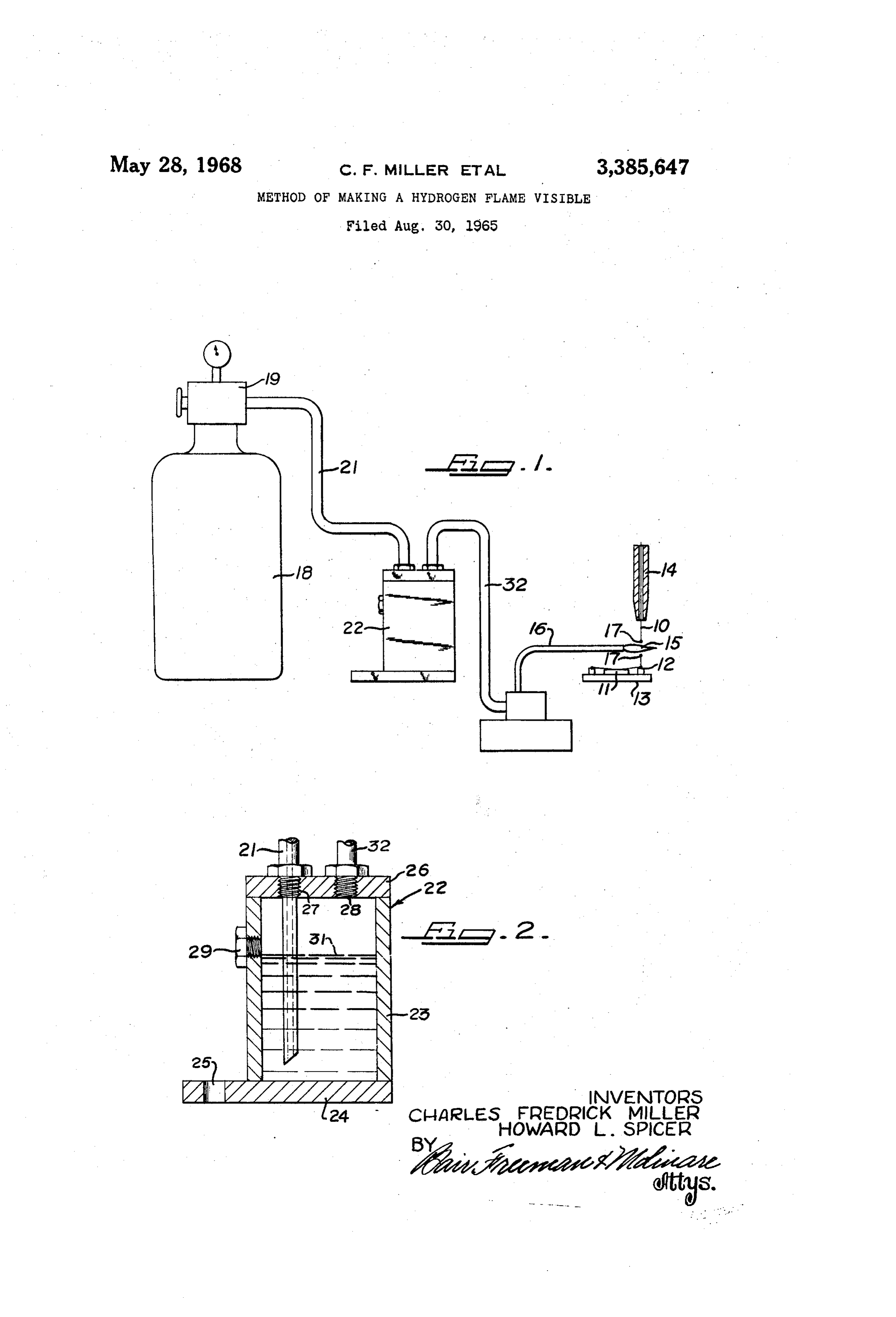
Filed Aug. 30, 1965, Ser. No. 483,647 As shown in FIG. 1 a fine gold wire indicated at 10 is 4. Claims. (C. 431-4) to be bonded between a semi-conductor wafer 11 and terminal posts 12 carried by a base 13 and forming a part
of a transistor assembly. As illustrated, short lengths of
ABSTRACT OF THE DISCLOSURE the wire are bonded between conductive areas on the outer Hydrogen is supplied to an alcohol-hydrogen torch face of the wafer 11 and the respective terminal posts through a sealed container of alcohol. The amount of 12The to form electrical connections therebetween. operation is performed in a known type of wire alcohol is thereby limited to the saturation point of alco bonding apparatus which includes a small capillary needle hol vapor in hydrogen. The burning alcohol insures a 14 through which the wire 10 is threaded. When the wire visible hydrogen-alcohol flame. 10 is cut by a flame as, for example, the hydrogen flame 15 emitted from a torch 16, the wire will be melted where 20 it is contacted by the flame and the ends thereof will
This invention relates to a method for making a hy form into generally spherical balls as shown at 17. These drogen flame visible and, more particularly, to the in balls are larger than the bore in the needle 14 so that parting of visibility to a fine hydrogen flame used in the when the needle is moved down the end of the needle will cutting and balling of the ends of fine gold wire in ball engage a ball and carry the wire down until the ball is bonding operations on semi-conductor devices Such as 25 pressed against either the conductive surface on the wafer transistors. or one of the terminal posts 12 to be bonded thereto. In bonding conductors to semi-conductor assemblies, After a connection has been completed the needle is such as transistors, one of the methods commonly em raised to approximately the position shown and the torch ployed is so-called “ball bonding.” In this method a fine is moved so that the flame will sweep across the wire be gold wire on the order of .0007' to .003' in diameter is 30 tween the last bonding point and the needle to sever the fed through a capillary needle and bonded by the needle wire and to cause balls to be formed on the severed ends to terminal posts and to conductor areas on Semi-conduc thereof.
tor wafers. After the last bond in a connection is formed, As shown, the torch is supplied with hydrogen from a the capillary needle is raised to expose the wire and the tank 18 through a suitable pressure regulating valve 19 wire is severed and formed into balls on its ends by pass and a conduit 21. The torch may be movably mounted ing a fine hydrogen flame across it. When the needle is for swinging across the wire and is carried by a portion again moved down for another bonding operation, it en of the wire bonding apparatus and is moved synchronous gages the ball on the end of the wire to feed the wire ly with movement of the needle or under the control of an against the surface to which it is to be bonded and to 40 operator to effect the severing of the wire at the desired press the ball against the surface to bond it thereto. times.
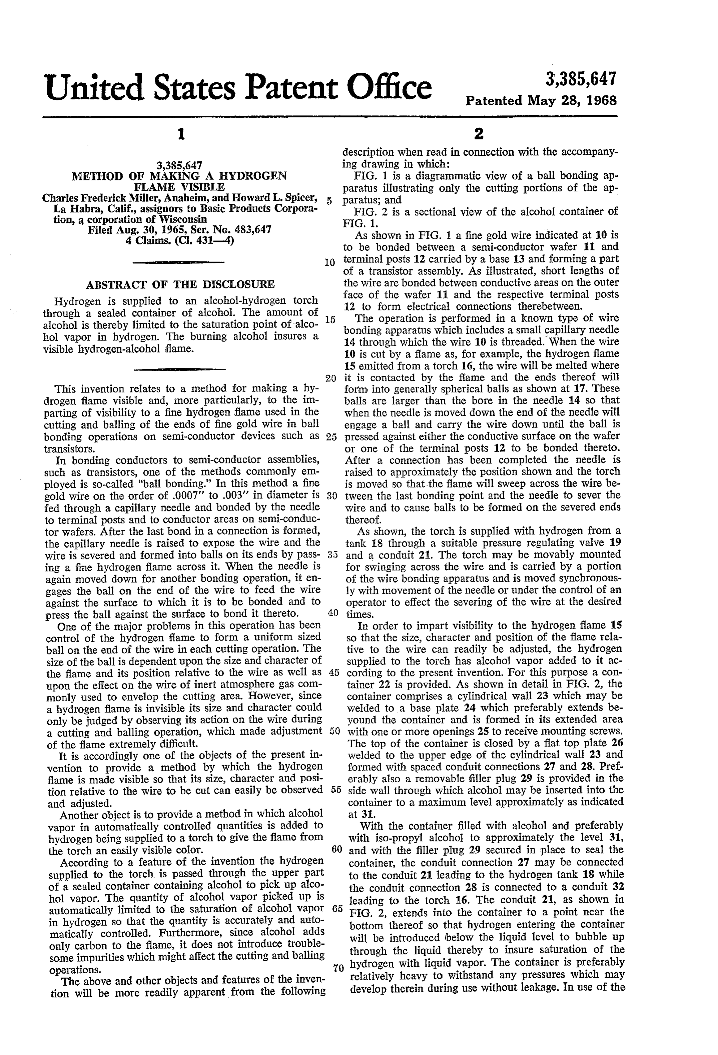
One of the major problems in this operation has been In order to impart visibility to the hydrogen flame 15 control of the hydrogen flame to form a uniform sized so that the size, character and position of the flame rela ball on the end of the wire in each cutting operation. The tive to the wire can readily be adjusted, the hydrogen size of the ball is dependent upon the size and character of supplied to the torch has alcohol vapor added to it ac the flame and its position relative to the wire as well as cording to the present invention. For this purpose a con upon the effect on the wire of inert atmosphere gas Com tainer 22 is provided. As shown in detail in FIG. 2, the monly used to envelop the cutting area. However, since container comprises a cylindrical wall 23 which may be a hydrogen flame is invisible its size and character could welded to a base plate 24 which preferably extends be only be judged by observing its action on the wire during yound the container and is formed in its extended area a cutting and balling operation, which made adjustment 5. with one or more openings 25 to receive mounting screws. of the flame extremely difficult. The top of the container is closed by a flat top plate 26 It is accordingly one of the objects of the present in welded to the upper edge of the cylindrical wall 23 and vention to provide a method by which the hydrogen formed with spaced conduit connections 27 and 28. Pref flame is made visible so that its size, character and posi erably also a removable filler plug 29 is provided in the tion relative to the wire to be cut can easily be observed 55 side wall through which alcohol may be inserted into the and adjusted. container to a maximum level approximately as indicated Another object is to provide a method in which alcohol at 31.
vapor in automatically controlled quantities is added to With the container filled with alcohol and preferably hydrogen being supplied to a torch to give the flame from 60 with iso-propyl alcohol to approximately the level 31, the torch an easily visible color. and with the filler plug 29 secured in place to seal the According to a feature of the invention the hydrogen container, the conduit connection 27 may be connected supplied to the torch is passed through the upper part to the conduit 21 leading to the hydrogen tank 18 while of a sealed container containing alcohol to pick up alco the conduit connection 28 is connected to a conduit 32 hol vapor. The quantity of alcohol vapor picked up is leading to the torch 16. The conduit 21, as shown in automatically limited to the saturation of alcohol vapor 65 FIG. 2, extends into the container to a point near the in hydrogen so that the quantity is accurately and auto bottom matically controlled. Furthermore, since alcohol adds will be thereof so that hydrogen entering the container introduced below the liquid level to bubble up only carbon to the flame, it does not introduce trouble through the liquid thereby to insure Saturation of the some impurities which might affect the cutting and balling hydrogen with liquid vapor. The container is preferably
relatively heavy to withstand any pressures which may
The above and other objects and features of the inven develop therein during use without leakage. In use of the tion will be more readily apparent from the following
Page 3
apparatus, the alcohol in the container will vaporize so 2. The method of claim 1 in which the alcohol vapor that the upper part of the container will be filled with is iso-propyl alcohol.
alcohol vapor. As the hydrogen from the tank flows 3. The method of making a hydrogen flame from a through the upper part of the container to the torch, torch visible which comprises supplying a stream of hy it will pick up alcohol vapor to the extent permitted by 5 drogen to the torch to burn in a flame, confining alcohol saturation of the hydrogen by the alcohol vapor. At the in a closed space, and passing the hydrogen stream flame both the hydrogen and the alcohol vapor will burn through the closed space to pick up alcohol vapor there simultaneously and the alcohol vapor present is sufficient from before the hydrogen stream reaches the torch. to give the flame a strong blue color which is readily 4. The method of claim 3 in which the hydrogen is visible to the eye. Therefore, since the flame can easily be observed, its size, character and position can easily 10 introduced into the closed space below the level of the alcohol therein.
be adjusted to perform the cutting and balling operation in the desired and most efficient manner. References Cited While one embodiment of the invention has been shown UNITED STATES PATENTS and described in detail, it will be understood that this is for the purpose of illustration only and is not to be taken 1,325,116 12/1919 Sebilk ----------- 158-117.5 as a definition of the scope of the invention, reference 1,718,732 6/1929 Danforth --------- 158-117.5 being had for this purpose to the appended claims. 2,003,864 6/1935 Nock ------------- 158-11 X What is claimed is:
1. The method of making a hydrogen flame from a 20 FOREIGN PATENTS torch visible which comprises supplying a stream of hy 486,170 3/1912 France.
drogen to the torch to burn in a flame and adding alcohol vapor to the hydrogen stream before it reaches the torch. JAMES W. WESTHAVER, Primary Examiner.
Provenance
- Collection
- Cited prior art
- Original PDF
- patentimages.storage.googleapis.com →
- Filed
- 1965-08-30
- Pages
- 3
- Method
- pdftotext (the PDF's own text layer) + pdftoppm 300dpi page scans
- Source
- Google Patents bibliographic record
- Granted
- 1968-05-28
- Inventors
- Miller Charles Frederick; Howard L Spicer; Basic Products Corp
- Transcribed from
- patentimages.storage.googleapis.com →