patent · US3350234
Flexible solar-cell concentrator array
31 October 1967
Page 1
Drawing sheet — no readable text.
Page 2
Drawing sheet — no readable text.
Page 3
United States Patent Office 3,350,234 Patented Oct. 31, 1967
concentration is achieved without unduly raising the tem
FLEXBLE SOLAR-CELL CONCENTRATOR perature efficiency.
of the solar cells and thereby lowering their
ARRAY
Louis A. Ule, Rolling Hills, Calif., assignor to Hoffman A further object is to provide such an improved re Electronics Corporation, a corporation of California flector-radiator light-concentrator type of solar-cell as Filed June 3, 1963, Ser. No. 285,447 sembly which is extremely reliable in its operation, and 7 Claims. (C. 136-89) yet which can be manufactured simply and inexpensively. The present invention relates to solar-cell concentrator Another object of the invention is to provide such an assemblies; and it relates more particularly to an im improved solar-cell assembly which includes light-reflec O tive surfaces constructed in an improved manner to ex proved reflective-radiator light-concentrator type of as hibit high reflective characteristics in the spectral range sembly which utilizes the capabilities of solar cells to the of the solar cells, and yet which has high emissivity so highest degree.
As is well known, the solar cell converts light energy as Yet to rapidly dissipate heat generated by the solar cells. another object of the invention is to provide such into electrical energy. The most common solar cell is the 5 an improved silicon photovoltaic cell. The silicon cell includes a sur light in weight,type so as of solar-cell panel assembly which is to be particularly adapted for mount face layer, and the exposure of the surface of the cell to ing in space vehicles where weight considerations are of light produces light absorption at the surface layer. Each paramount importance.
light photon so absorbed by the surface layer of the silicon A further object of the invention is to provide such an photovoltaic cell displaces an electron, and the net result 20 improved solar-cell light-concentrator panel assembly is that the cell functions as an electric current generator. which includes a plurality of individual modular units in In the usual solar-cell panel, a plurality of these cells are tercoupled in side-by-side relationship to form either a connected in series and/or parallel to provide the desired rigid panel or a flexible array, whichever may be desired. voltage and current capabilities. Yet a further object is to provide such an improved Solar-cell panels have found a wide range of utility. 25 solar-cell panel assembly which is capable of resisting One particular use for the solar-cell panel in recent years thermal shock and mechanical vibrations. has been in space vehicles. For example, solar-cell instal Another object is to provide such an improved solar lations have been used in space probes, military and com cell panel assembly which is easy to repair, and in which munication satellites, and the like. The power derived the modular construction enables malfunctioning compo from such cells in response to incident sunlight is used 30 nents to be easily replaced.
in the space vehicles, for example, to excite the radio The improved light-concentrator solar battery assem communication equipment. bly of the invention is composed, in the embodiment to The usual prior art solar-cell assembly for use, for ex be described, of a plurality of honeycombed elongated ample, in space vehicles has usually been in the form of trough-like modules. These modules are composed of a rigid panels. A plurality of solar cells are mounted on 35 light metal, for example, such as aluminum; and their the individual panels in the prior art arrangements, and the cells are interconnected electrically to provide the weight. A thin shell is provided forthem honeycomb configuration renders extremely light in each of the modules, desired electrical power. and this shell provides the reflective and mounting sur The ratio of cost and weight with respect to the gen faces for the module.
erated electric power of the usual prior art solar-cell 40
The modules mentioned in the preceding paragraph panel has been found to be excessively high. It has been found that one reason for this high ratio is the low per can, as mentioned above, be assembled in side-by-side re lationship into a rigid panel, if such is desired; or they centage of actual available light which reaches the sensi may be formed into a jointed, articulated flexible array. tive surface of the individual solar cells which make up the panel. For that reason, attempts have been made in 45 The latter array is most convenient, as it can be wrapped around a curved Surface, this being a convenient mount the past to incorporate reflectors, and the like, into the ing arrangement for launching purposes. The panel as solar-cell panels, so as to increase the concentration of sembly to be described is constructed so that when it is Solar energy reaching the sensitive surfaces of the solar So mounted in the launching position it presents a con cells.
venient bearing
The above-mentioned attempts have met with some suc 50 and it also is constructedsurface for the curved mounting means, so that when so mounted in cess in the prior art in decreasing the ratio of weight and the launching position, its sensitive surfaces face inward cost to generated power in the resulting assemblies. The ly and are protected.
present invention is particularly concerned with such a The construction to be described also incorporates im reflective, light-concentrator structure; and a primary ob proved electric connections which are not susceptible to ject of the invention is to provide a reflective-radiator, 55 fracture in the presence of high mechanical shocks. In light-concentrator solar-cell assembly which incorporates addition, the individual modules are mechanically inter improved electrical, mechanical, thermal and optical fea coupled in a spring-biased hinged relationship, in the em tures so as to increase its over-all efficiency and utility. bodiment to be described, so as to constitute a strong, A more general object of the invention is to provide an 60 rugged assembly from a mechanical standpoint. improved reflector-radiator light-concentrator type of Other objects and advantages of the invention will be solar-cell panel assembly which utilizes the capabilities of come apparent from a consideration of the following de solar cells to the highest degree so as to provide a rela with Scription, and when the description is taken in conjunction tively high amount of electric power at relatively low the accompanying drawings, in which: weight and cost of the generating assembly. FIGURE 1 is a fragmentary perspective view showing 65 portion of a solar-cell reflective panel assembly con
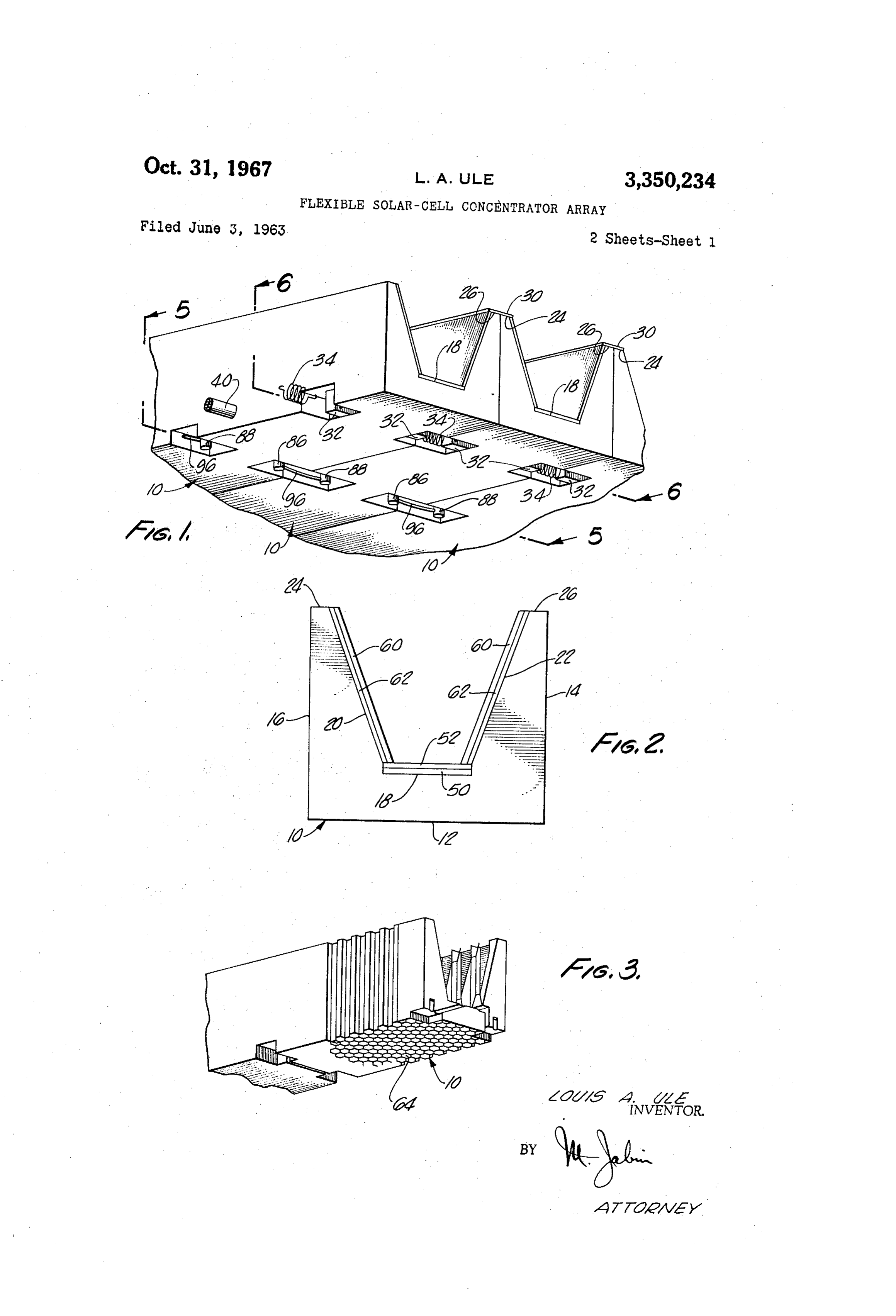
A more specific object of the invention is to provide astructed in accordance with one embodiment of the inven Such an improved reflector-radiator solar-cell panel as tion, and which is composed of a plurality of modules sembly by which the light input to the solar cells in the mounted in side-by-side relationship; assembly is increased by reflective light concentration;
FIGURE 2 is an end view of one of the modules of and in which the assembly exhibits relatively high radiat 70 FIGURE ing characteristics, so that the increase in reflective light 1, and illustrating particularly an improved construction for the reflective surfaces of the module;
Page 4
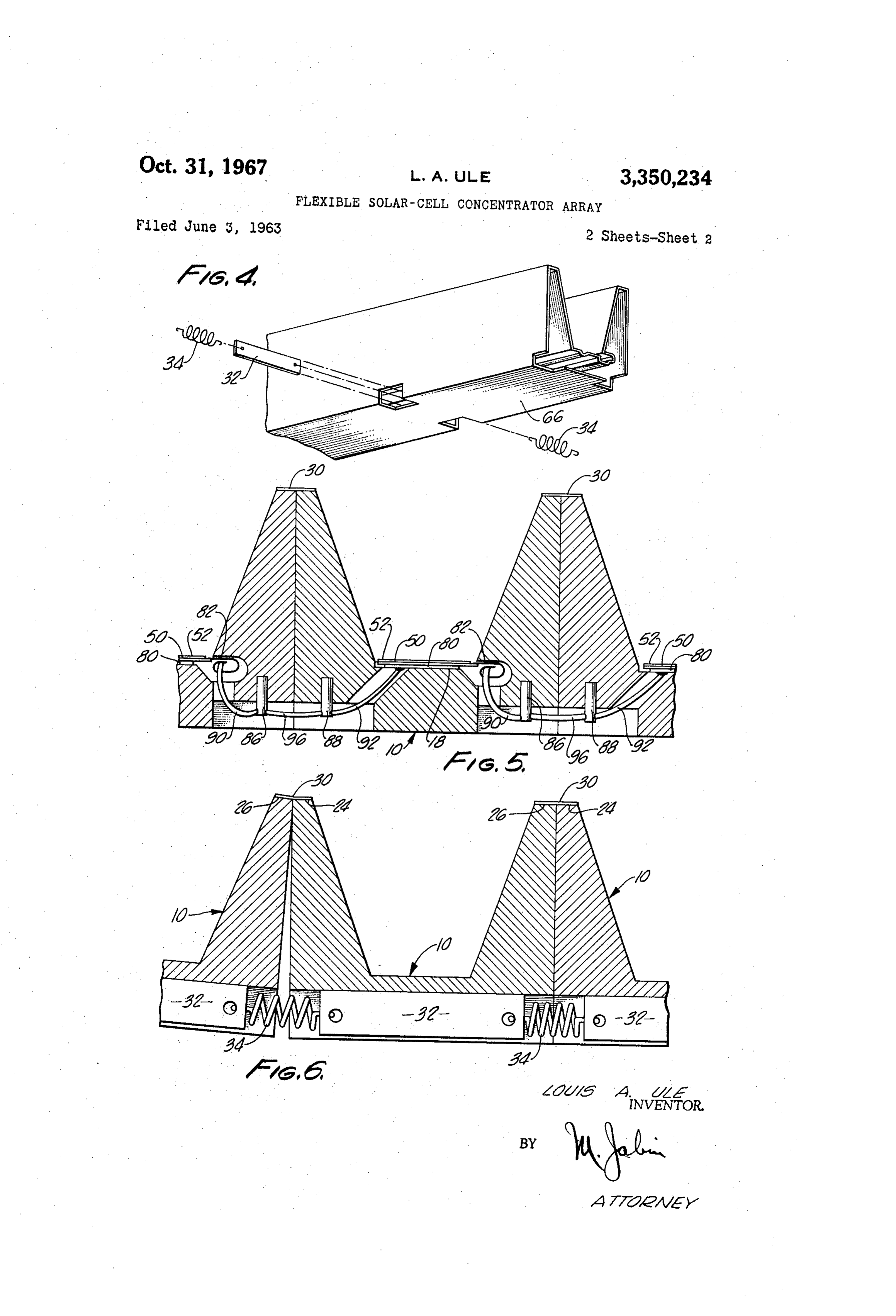
FIGURE 3 is a fragmentary perspective view of a As mentioned above, the improved construction of the module constructed in accordance with one of the aspects present invention permits the array of modules 10 to be of the invention, and including a honeycomb configuration wrapped around a curved surface of the space vehicle in so as to be light in weight; the launch configuration. In the launch configuration, the FIGURE 4 is a perspective view of a skin, or shell, arrays constructed in accordance wtih the invention may member which is adapted to fit over the honeycomb mod measure up to ten feet in length and several feet in width; ule of FIGURE 3 so as to provide reflective and other and these arrays are wrapped around the typically curved surfaces for the module; surface of such vehicles.
FIGURE 5 is a sectional view, taken substantially When in the above-mentioned launching position, the along the line 5-5 of FIGURE 1, and showing the elec 0. surfaces 24 and 26 serve as bearing surfaces; and the trical connections to the Solar cells supported in the as mounting surface 18 of each module, and the sensitive sembly; and cells mounted thereon, are held in a protected facing-in FIGURE 6 is a sectional view, taken substantially along position with respect to the curved surface of the mis the line 6-6 of FIGURE 1, and illustrating the means by sile. In this manner, considerable protection is afforded which the individual units are mechanically coupled to 15 against both weather and aerodynamic buffeting. The ex one another. posed inactive surface of the array is made strong enough As illustrated in FIGURE 1, for example, an improved to withstand thermal and mechanical shocks. light-concentrator Solar battery assembly constructed in When the space vehicle supporting the modular array accordance with one embodiment of the invention includes of the invention has been launched, and the array is a plurality of elongated trough-like modules 10. The mod 20 ready for use, appropriate mounting bands are removed ules 10 are mounted in side-by-side relationship in the by any appropriate control, and the springs 34 and the illustrated embodiment to form a jointed, articulated, Spring biased safety cable 40 cause the flexible array to flexible array. straighten out and assume its operative planar configura As shown in FIGURE 2, each of the elongated modules tion.
10 may have a generally rectangular configuration. Each 25 As shown in FIGURE 2, a plurality of light sensitive module may have dimensions of the order, for example, cells, such as the solar cell 50, are mounted on the mount of 2 inches by 2 inches by 10 feet. ing surfaces 18 of the modules 10. These solar cells are Each of the modules 10 includes a bottom surface 12. protected by a conventional glass cover 52. The inclined The modules 10 further include a pair of side surfaces 14 Surfaces 20 and 22 of each module serve as reflective and 16, and each includes a mounting surface 18 which 30 Surfaces. These surfaces make it possible to reflect sun light to the solar cells mounted on surface 18 at the extends the length of the module parallel to the bottom surface 12. A pair of outwardly inclined surfaces 20 and bottom of the trough. It is also important that the reflec 22 extend upwardly from the mounting surface 18, and tive Surfaces 20 and 22 serve to conduct heat away from these latter surfaces are inclined with respect to cor the Solar cells and to radiate the heat, so that the solar responding ones of the side surfaces 14 and 16. A pair 35 cells will not become excessively heated. It is well known of heat radiating bearing surfaces 24 and 26 extend the that the efficiency of the solar cells drops as their tem length of the module between the respective upper edges perature rises.
of the inclined surfaces 20 and 22 and the corresponding A requirement for the reflective surfaces 20 and 22, upper edges of the side surfaces 14 and 16. therefore, is to provide high reflectivity in the spectral The adjacent modules 10 in FIGURE 1 are mechanical 40 range of the solar cell sensitivity, that is, in a range of ly joined to one another by flexible strap hinges, such as Wavelengths extending, for example, from 0.4-3 microns. the hinges 30. These hinges are affixed to the heat-radiat It is also desirable for the reflective surfaces 20 and 22 ing bearing surfaces 24 and 26, and they extend along the to exhibit a high emissivity at around 60° centigrade. length of the assembly. The strap hinges are shown in The reflective surfaces 20 and 22 may be formed of greater detail in FIGURE 6. 45 aluminum sheet, for example. An appropriate aluminum The hinged modules of FIGURE 1 are held in a spring sheet for this purpose is presently being marketed by the biased manner in the illustrated planar configuration. This Aluminum Company of America, and is designated by is achieved by a mechanical coupling which includes a them by the trade name “Alzak." This sheet is extremely plurality of links 32 (FIGURE 6) respectively associated light, and it includes a pure aluminum layer on each side. with each of the modules 10 and extending transversely 50 One side of the sheet is highly polished, so as to serve thereacross; and a corresponding plurality of coil springs as the reflective surface. The sheet, however, exhibits rela 34 which intercouple adjacent ones of the links 32 to one tively low emissivity. This can be increased, however, by another. It could also be achieved by other means, such a heavy anodizing of the sheet. The resulting structure as a continuous beryllium-copper strap spring which is has been found to provide approximately 75% reflectivity cemented to the rear of each module. in the spectral range of the solar cell, and 65% emissivity The links 32 can be formed, for example, of glass rein 55 at 60 centigrade. The anodized surface does not survive forced epoxy resin, or of any other suitable material. the vacuum and ultraviolet environment of Space. The springs 34 may incorporate, for example, appropriate In the construction of FIGURE 2, however, the reflec mechanical damping and appropriate mechanical stops tive surfaces are formed differently and in the following So as to limit the arcuate bending of the modular as manner: A transparent member 60 is provided. This trans sembly about the hinge axes. parent member may, for example, be an extremely thin In practice, it is preferable to thread a spring loaded glass sheet. Glass sheets of the type presently marketed by Safety cable 40 transversely through the adjacent modules the Corning Company, and designated by them by the 10. The safety cable threading through the array may be trade name "Microsheet,” are suitable for this purpose. held taut by a spring at one end. This spring may be 65 These glass sheets have a thickness, for example, of .006 mounted inside a dash pot. The safety cable serves as a positive spring means for returning the modular array inch. The transparent members 60 are provided with a silver from a curved to a flat planar position. Also, the mechani cal damping provided by the dash pot serves to prevent backing 62 to render them reflective. This silver backing destructive whiplash upon the deployment of the array. 70 is applied by any appropriate means. The silver-backed Moreover, the safety cable assembly serves as a mechani transparent members are then attached to the surfaces 20 cal stop to limit the extent to which the flexible modular and 22 by any appropriate adhesive. array may be wrapped around the curved launching sur The resulting reflective surfaces, constructed in the face, and may replace completely the links 32 or other manner shown in FIGURE 2, have high emissivity, as a strap spring. 75 result of the inherent high emissivity of the transparent
Page 5
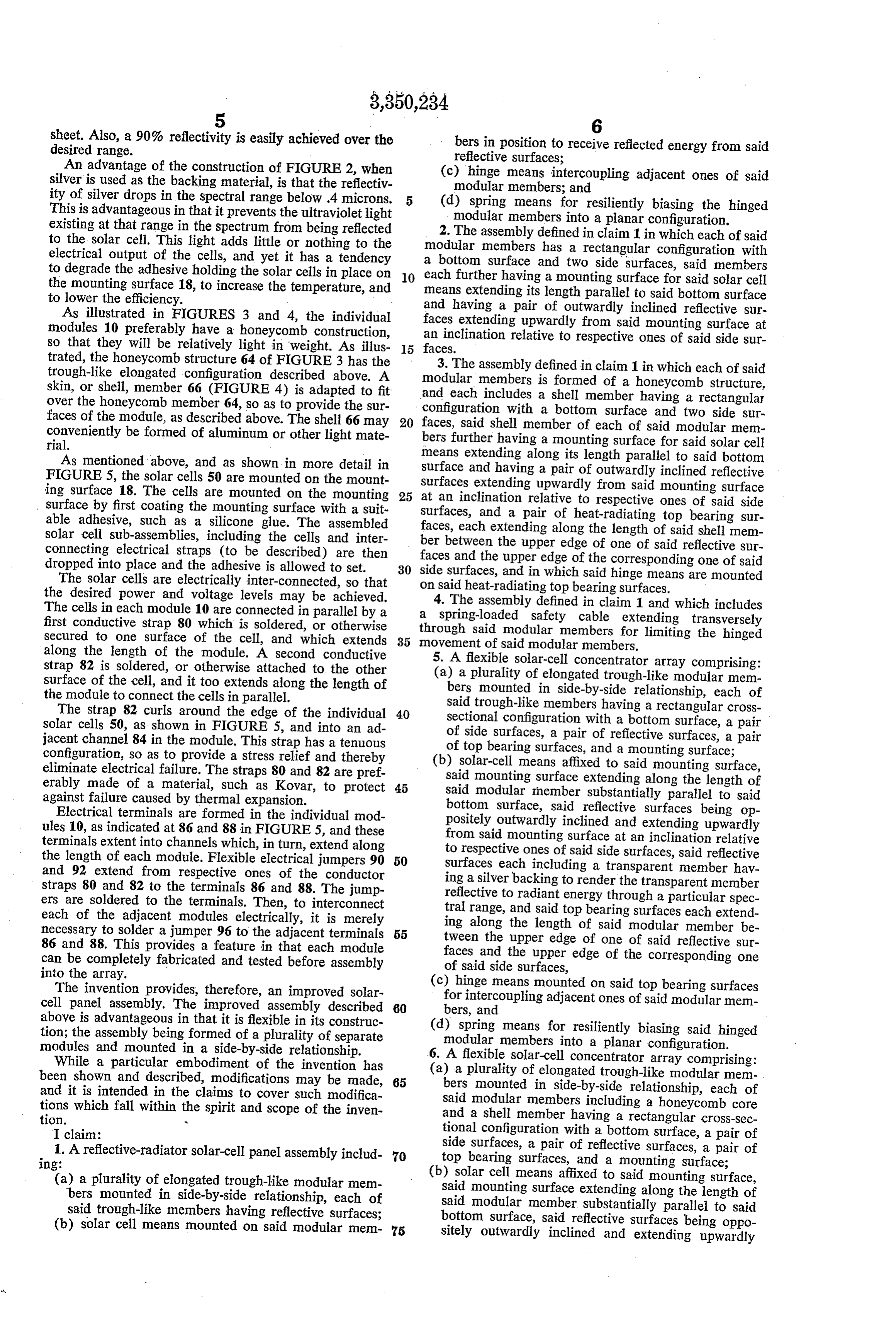
sheet. Also, a 90% reflectivity is easily achieved over the bers in position to receive reflected energy from said desired range. reflective surfaces;
An advantage of the construction of FIGURE 2, when (c) hinge means intercoupling adjacent ones of said silver is used as the backing material, is that the reflectiv modular members; and ity of silver drops in the spectral range below .4 microns. (d) spring means for resiliently biasing the hinged This is advantageous in that it prevents the ultravioletlight modular members into a planar configuration. existing at that range in the spectrum from being reflected 2. The assembly defined in claim 1 in which each of said to the solar cell. This light adds little or nothing to the modular members has a rectangular configuration with electrical output of the cells, and yet it has a tendency to degrade the adhesive holding the solar cells in place on 10 aeach bottom surface and two side surfaces, said members further having a mounting surface for said solar cell the mounting surface 18, to increase the temperature, and means extending its length parallel to said bottom surface to lower the efficiency. and having a pair of outwardly inclined reflective sur As illustrated in FIGURES 3 and 4, the individual faces extending upwardly from said mounting surface at modules 10 preferably have a honeycomb construction, an inclination relative to respective ones of said side sur so that they will be relatively light in weight. As illus 15 faces.
trated, the honeycomb structure 64 of FIGURE 3 has the 3. The assembly defined in claim 1 in which each of said trough-like elongated configuration described above. A modular members is formed of a honeycomb structure, skin, or shell, member 66 (FIGURE 4) is adapted to fit over the honeycomb member 64, so as to provide the sur and each includes a shell member having a rectangular faces of the module, as described above. The shell 66 may 20 configuration faces, said with a bottom surface and two side sur shell member of each of said modular mem conveniently rial.
be formed of aluminum or other light mate bers further having a mounting surface for said solar cell As mentioned above, and as shown in more detail in means extending along its length parallel to said bottom FIGURE 5, the solar cells 50 are mounted on the mount surface and having a pair of outwardly inclined reflective surfaces ing surface 18. The cells are mounted on the mounting 25 at an inclination extending upwardly from said mounting surface surface by first coating the mounting surface with a suit surfaces, and a pair relative to respective ones of said side able adhesive, such as a silicone glue. The assembled of heat-radiating top bearing sur solar cell sub-assemblies, including the cells and inter faces, each extending along the length of said shell mem connecting electrical straps (to be described) are then faces ber between the upper edge of one of said reflective sur dropped into place and the adhesive is allowed to set. 30 side surfaces, and the upper edge of the corresponding one of said The solar cells are electrically inter-connected, so that and in which said hinge means are mounted the desired power and voltage levels may be achieved. on said heat-radiating top bearing surfaces. The cells in each module 10 are connected in parallel by a 4. The assembly defined in claim 1 and which includes a spring-loaded safety cable extending transversely first conductive strap 80 which is soldered, or otherwise through secured to one surface of the cell, and which extends 35 movementsaid modular members for limiting the hinged of said modular members.
along the length of the module. A second conductive 5. A flexible solar-cell concentrator array comprising: strap 82 is soldered, or otherwise attached to the other (a) a plurality of elongated trough-like modular mem surface of the cell, and it too extends along the length of bers mounted in side-by-side relationship, each of the module to connect the cells in parallel. said trough-like members having a rectangular cross The strap 82 curls around the edge of the individual 40 sectional configuration with a bottom surface, a pair solar cells 50, as shown in FIGURE 5, and into an ad of side surfaces, a pair of reflective surfaces, a pair jacent channel 84 in the module. This strap has a tenuous of top bearing surfaces, and a mounting surface; configuration, so as to provide a stress relief and thereby (b) solar-cell means affixed to said mounting surface, eliminate electrical failure. The straps 80 and 82 are pref said mounting surface extending along the length of erably made of a material, such as Kovar, to protect 45 said modular member substantially parallel to said against failure caused by thermal expansion. bottom surface, said reflective surfaces being op Electrical terminals are formed in the individual mod positely outwardly inclined and extending upwardly ules 10, as indicated at 86 and 88 in FIGURE 5, and these from said mounting surface at an inclination relative terminals extent into channels which, in turn, extend along to respective ones of said side surfaces, said reflective the length of each module. Flexible electrical jumpers 90 50 surfaces each including a transparent member hav and 92 extend from respective ones of the conductor ing a silverbacking to render the transparent member straps 80 and 82 to the terminals 86 and 88. The jump reflective to radiant energy through a particular spec ers are soldered to the terminals. Then, to interconnect tral range, and said top bearing surfaces each extend each of the adjacent modules electrically, it is merely ing along the length of said modular member be necessary to solder a jumper 96 to the adjacent terminals 55 tween the upper edge of one of said reflective sur 86 and 88. This provides a feature in that each module faces and the upper edge of the corresponding one can be completely fabricated and tested before assembly of said side surfaces, into the array.
The invention provides, therefore, an improved solar (c) hinge means mounted on said top bearing surfaces cell panel assembly. The improved assembly described 60 for intercoupling adjacent ones of said modular mem above is advantageous in that it is flexible in its construc bers, and tion; the assembly being formed of a plurality of separate (d) spring means for resiliently biasing said hinged modules and mounted in a side-by-side relationship. modular members into a planar configuration. While a particular embodiment of the invention has 6. A flexible solar-cell concentrator array comprising: been shown and described, modifications may be made, 65 (a)bers a plurality of elongated trough-like modular mem- . mounted in side-by-side relationship, each of and it is intended in the claims to cover such modifica said modular members including a honeycomb core tions which fall within the spirit and scope of the inven and a shell member having a rectangular cross-sec tion.
I claim: tional configuration with a bottom surface, a pair of 1. A reflective-radiator solar-cell panel assembly includ 70 side surfaces, a pair of reflective surfaces, a pair of 1ng: top bearing surfaces, and a mounting surface; (a) a plurality of elongated trough-like modular mem (b) solar cell means affixed to said mounting surface, bers mounted in side-by-side relationship, each of said mounting surface extending along the length of said trough-like members having reflective surfaces; said modular member substantially parallel to said (b) solar cell means mounted on said modular mem 75 bottom surface, said reflective surfaces being oppo sitely outwardly inclined and extending upwardly
Page 6
from said mounting surface at an inclination relative . . References Cited to respective ones of said side surfaces, said reflective UNITED STATES PATENTS surfaces each including a transparent member having a silver backing to render the transparent member 2,904,612 9/1959 Regnier ------------- 136-89 reflective to radiant energy through a particular spec- 5 2,919,298 12/1959 Regnier et al. --------- 136-89 tral range, and said top bearing surfaces each extend- 2,989,575 6/1961 Wallace ------------- 136-89 ing along the length of said modular member be- 3,005,979 10/1961 Rochard et al.------ 136-89 X tween the upper edge of one of said reflective sur- 3,232,795 2/1966 Gillette et al. --------- 136-89 faces and the upper edge of the corresponding one of OTHER REFERENCES said side surfaces, w 10 Dale, B., et al.: Proc. 14th Ann. Power Sources Conf., (c) hinge means mounted on said top bearing surfaces October 1960, pp. 22-25 for intercoupling adjacent ones of said modular mem- Herchakowski, A., et al.: Proc. 15th Ann. Power bers, and oa A w Sources Conf., October 1961, pp. 120-124. (d) spring means for resiliently biasing said hinged Johnson, A. L.: "Spacecraft Radiators,' in Space/Aero modular members into a planar configuration. 15 nautics January 1962 pp. 76-82 s 7. A concentrator array as defined in claim 6 including, Manh A.: Proc. 1 4th Ann Power Sources Conf., Oc in addition, an electrical conduit adjacent said mounting tober 1960, pp. 2832. s surface, said conduit being shielded from incident radia tion by one of said reflective surfaces and said solar cell ALLEN B. CURTIS, Primary Examiner. means so as to provide ample space for an electrical con- 20 nection to said solarcell means without being an inac.
tive area which is exposed to incident radiation.
WINSTON A. DOUGLAS, Examiner.
A. M. BEKELMAN, Assistant Examiner.
Provenance
- Collection
- Cited prior art
- Original PDF
- patentimages.storage.googleapis.com →
- Filed
- 1963-06-03
- Pages
- 6
- Method
- pdftotext (the PDF's own text layer) + pdftoppm 300dpi page scans
- Source
- Google Patents bibliographic record
- Granted
- 1967-10-31
- Inventors
- Louis A Ule; Hoffman Electronics Corp
- Transcribed from
- patentimages.storage.googleapis.com →