patent · US3296775
Method and apparatus for treating fluids and non-fluid materials
10 January 1967
Page 1
Drawing sheet — no readable text.
Page 2
Drawing sheet — no readable text.
Page 3
Drawing sheet — no readable text.
Page 4
Drawing sheet — no readable text.
Page 5
United States Patent Office 3,296,775 Patented Jan. 10, 1967
Surge flow of gas is passed through the granular material 3,296,775 and the one perforate wall in a reverse direction to effect METHOD AND APPARATUS FOR TREATING removal of a portion of the granular material adjacent FUSDS AND NON-FUD MATERALS and including the free granular material surfaces. Arthur Morton Squires, 245 W. 104th St., More particularly, the gaseous fluid-solid contactor of New York, N.Y. 10.025 this invention comprises a pair of upwardly extending Continuation of applieation Ser. No. 230,822, Oct. 16, horizontally spaced-apart perforate retaining walls, a
12 Claims. (C. 55-98) gaseous fluid inlet compartment adjacent and in com munication with the perforations of a first of the per
This application is continuation of my copending appli O forate walls, a gaseous fluid outlet compartment adjacent cation, Serial No. 230,822, filed October 16, 1962. and in communication with the perforations of the sec The present invention relates to the art of contacting ond of the perforate walls, closure means about the space a bed of sand or granular material and a fluid with one between the first and second perforate walls closing said another to effect treatment of one or both of them, and is Space against the passage of gas except through the per particularly concerned with the periodic removal of the 5 forations of said perforate walls, feed means for supply granular material adjacent the fiuid entry face of the gran ing a loose solid particulate material into the space be ular material bed while retaining the remainder of the tween the perforate walls, a plurality of particulate ma bed. terial support members each adjacent a perforation of The treatment of fluids, and in particular gases, and said first perforate wall, said particulate-material support granular solids by contacting one with the other is of 20 members being arranged to extend outwardly and up extreme technical importance in a number of industrial wardly from below their adjacent perforations and into fields for various purposes including coal gasifications, the inlet compartment to support and expose to the inlet catalytic contacting, gas absorption, gas adsorption, and compartment a plurality of free surfaces of particulate filtering particulate material from gases. material, an inlet for admitting a gaseous fluid into the A recognized means for contacting solids and gases was inlet compartment for passage into the free surfaces and to form one or more panel contactors, with each panel through the particulate material to the outlet compart contactor comprising a long narrow vertical bed of gran ment, an outlet for discharging gaseous fluid from the out ular material retained between opposed perforate Walls. let compartment, means for periodically effecting a mass The gases were caused to pass through the contactor panel 30 movement toward the inlet compartment of at least those in the narrow direction of the bed. The opposed perforate portions of the particulate material including said three walls retaining the granular material were made of wire surfaces and which are retained on said supporting mem mesh screen, perforated metal sheets, or slat-like members bers, said mass-movement means comprises a source of mounted in Venetion blind fashion. gas under pressures, means for effecting a sudden dis Panel contactors of the aforementioned type provided a charge of gas from the pressure source into the outlet considerable amount of gas-solids contact area per unit compartment and against the particulate material at a floor space occupied by the contactor, but in spite of the sharply peaking rate of gas flow having a peak value sub space advantage, this type of gas-solids contactor had stantially in excess of the minimum steady flow rate at little practical utility because there was no satisfactory which a flow of gas causes motion of the particulate ma way of removing the used up or spent granular material 40 terial, volume control means for limiting the quantity of from the bed. The usual manner of removing the spent gas discharged into the outlet compartment to provide an granular material was by draining the entire bed of Solids immediate decline in the fate of gas flow following the from the bottom of the panel, and completely replenish peak rate to control the quantity of particulate material ing the bed with a corresponding amount of fresh granular displaced from the material support members, and means material added at the top of the panel. Large amounts of for discharging from the inlet compartment material material and considerable storage space were needed for which is displaced thereinto by the mass movement means. the panel to be kept in substantially continuous use. The present invention provides for cleaning the fluid Moreover, by discharging the granular material from entry face of a granular material contactor panel by caus the bottom of the panel a considerable amount of fresh ing a surge flow of gas through granular material at an or unspent granular material was removed from the panel, intensity and volume to cause the granular material to notably material from the interior and gas-exit portions move in a mass toward the outer edges of supporting of the bed. When contacting a bed of granular material members and to cause a portion of the granular material with a gas, it is the solids nearest the point at which gas to spill from the supporting members. The quantity of enters the bed which are used up, and which need be re solids removed from the contactor may be held to a placed after a period of use. It would be desirable to re 5 5 small fraction of the total quantity of solids in the move the spent or used up solids, that is the granular contactOr.
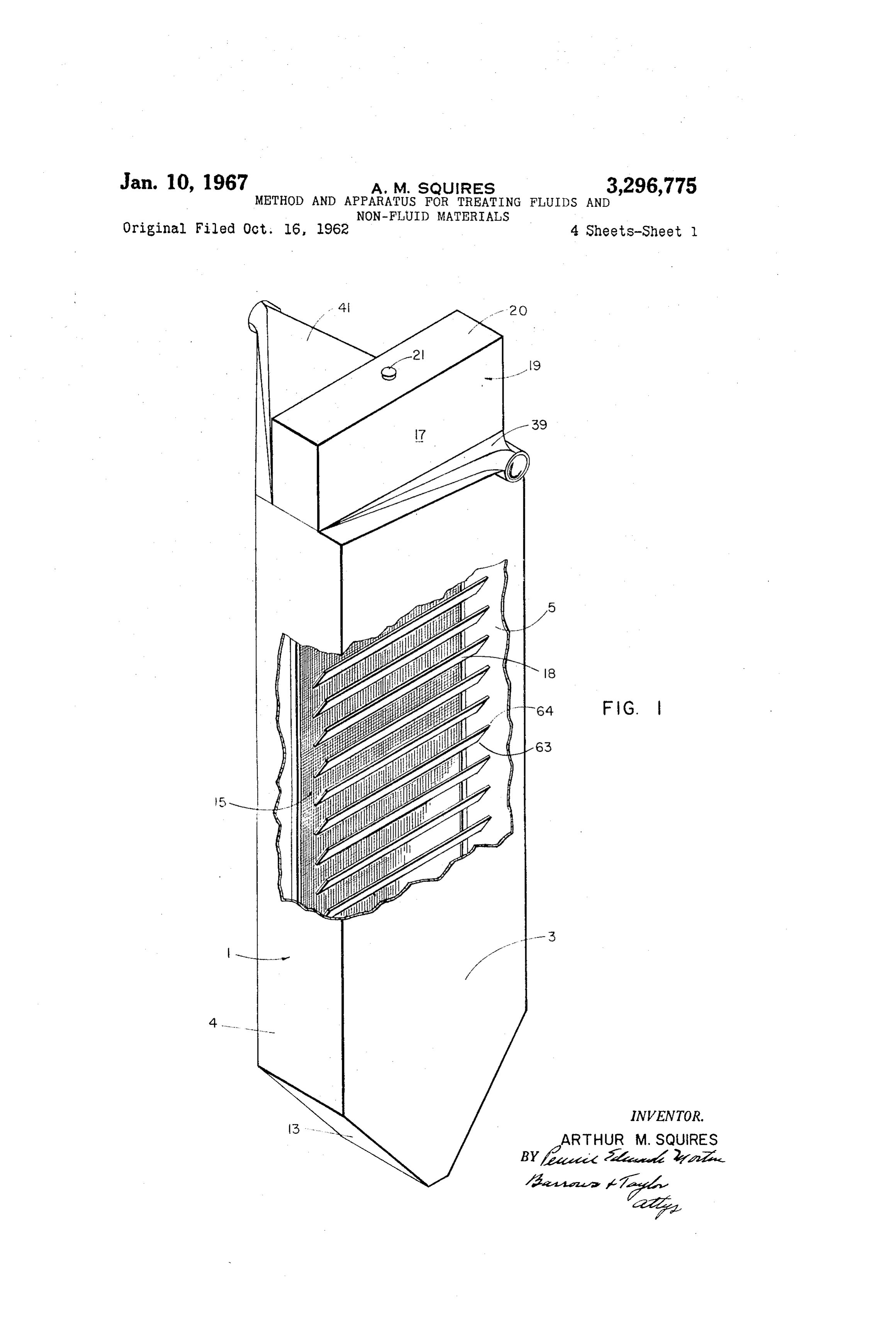
material in the gas entry portion of the bed, while retain The invention will be more particularly described in ing the fresh or nonspent granular material in the interior conjunction with the following drawings wherein: and gas exit portions of the bed. FIG. 1 is a perspective view, partly broken away, of a The present invention embodies a fluid-solids contactor 60 preferred contacting panel, with the sand removed, which comprising a bed of granular material retained between panel is particularly suitable for use as a dust collector and two upwardly extending perforate walls, with the bed will be so described;
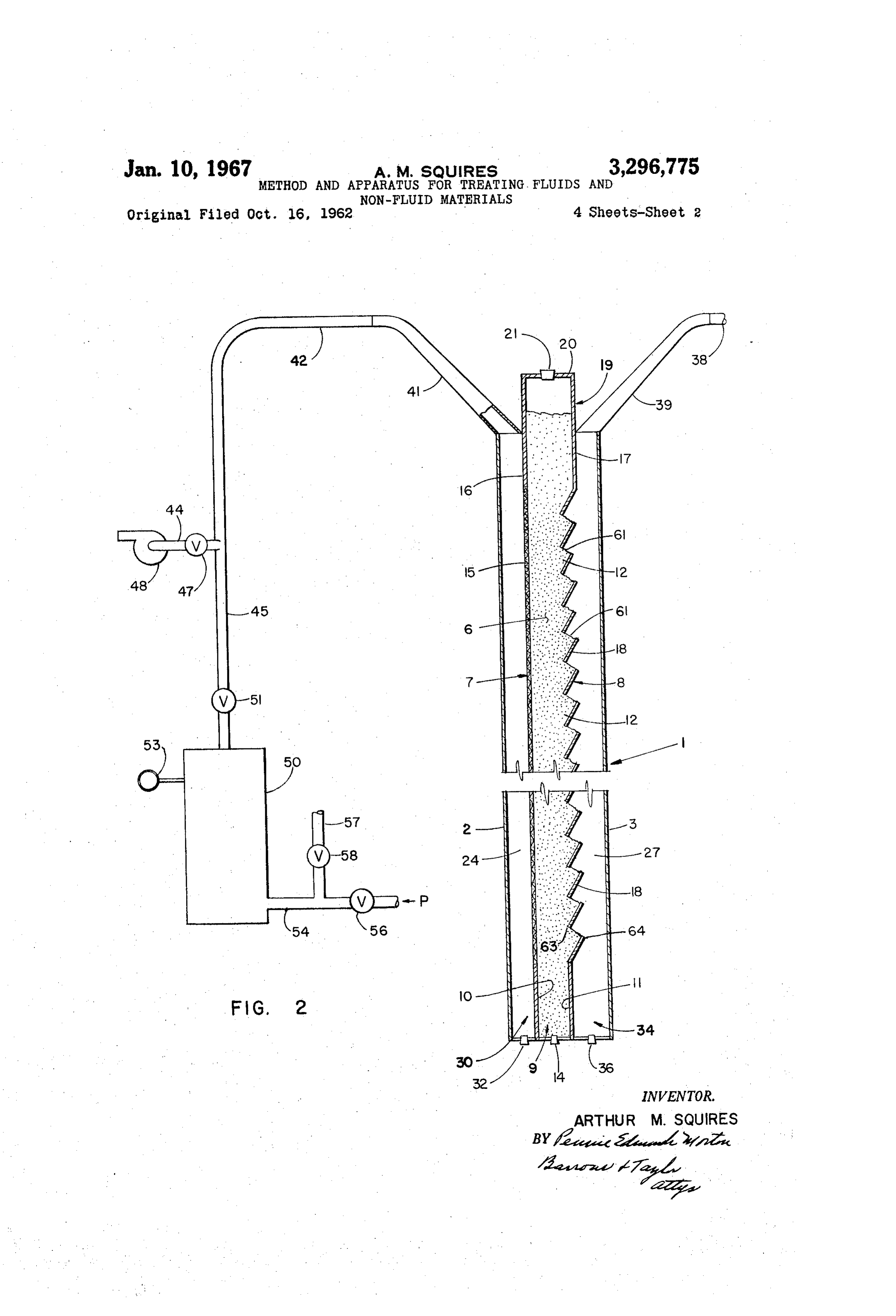
having free granular material surfaces adjacent one of the FIG. 2 is a vertical sectional view of the filter panel perforate walls. Fluid is passed into contact with the free in FIG. 1, with a bed of sand;
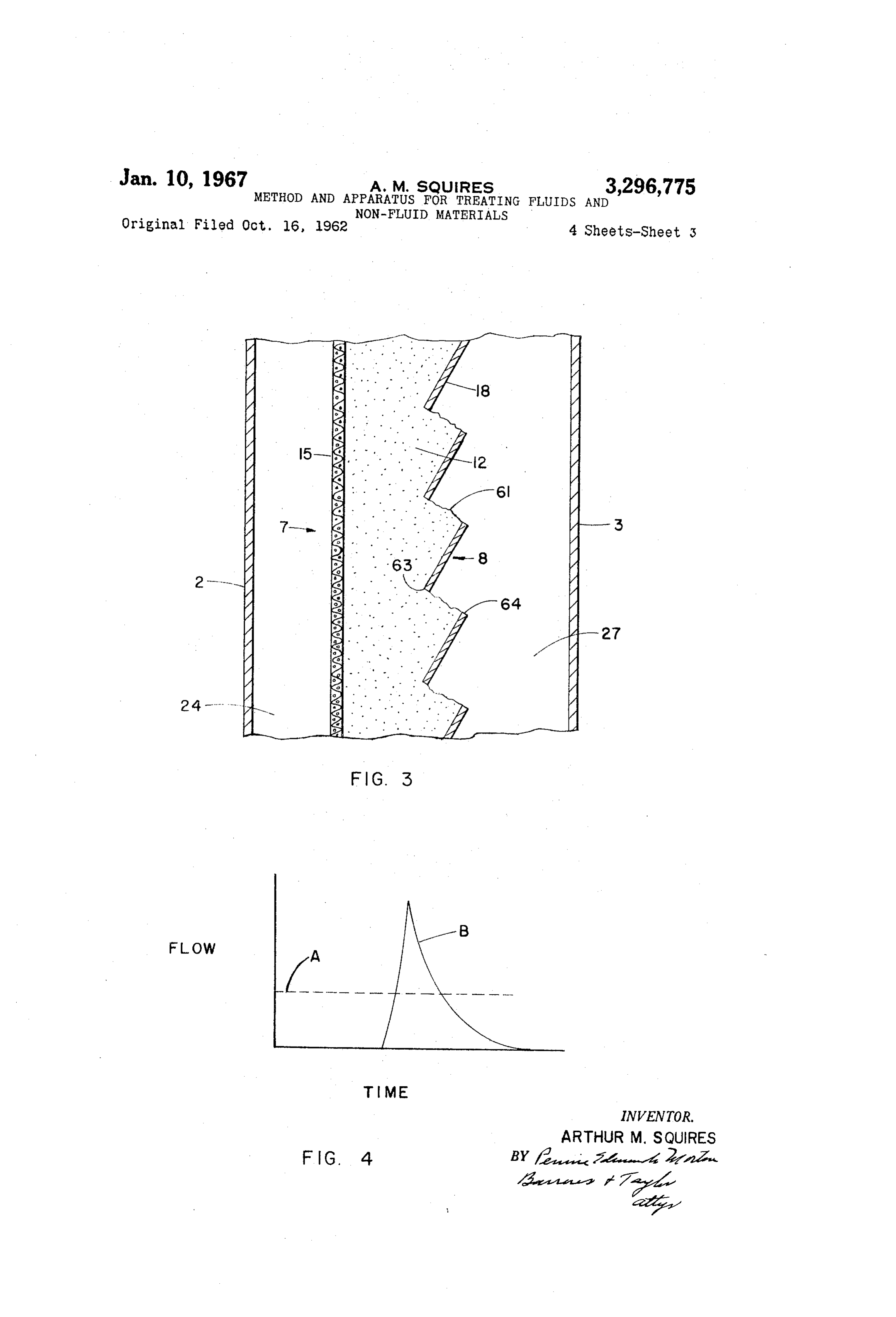
granular surfaces and through the bed to effect treatment FIG. 3 is an enlarged view of a portion of the louvers of the fluid or granular material. Periodically a reverse and sand bed of FIG. 2;
Page 6
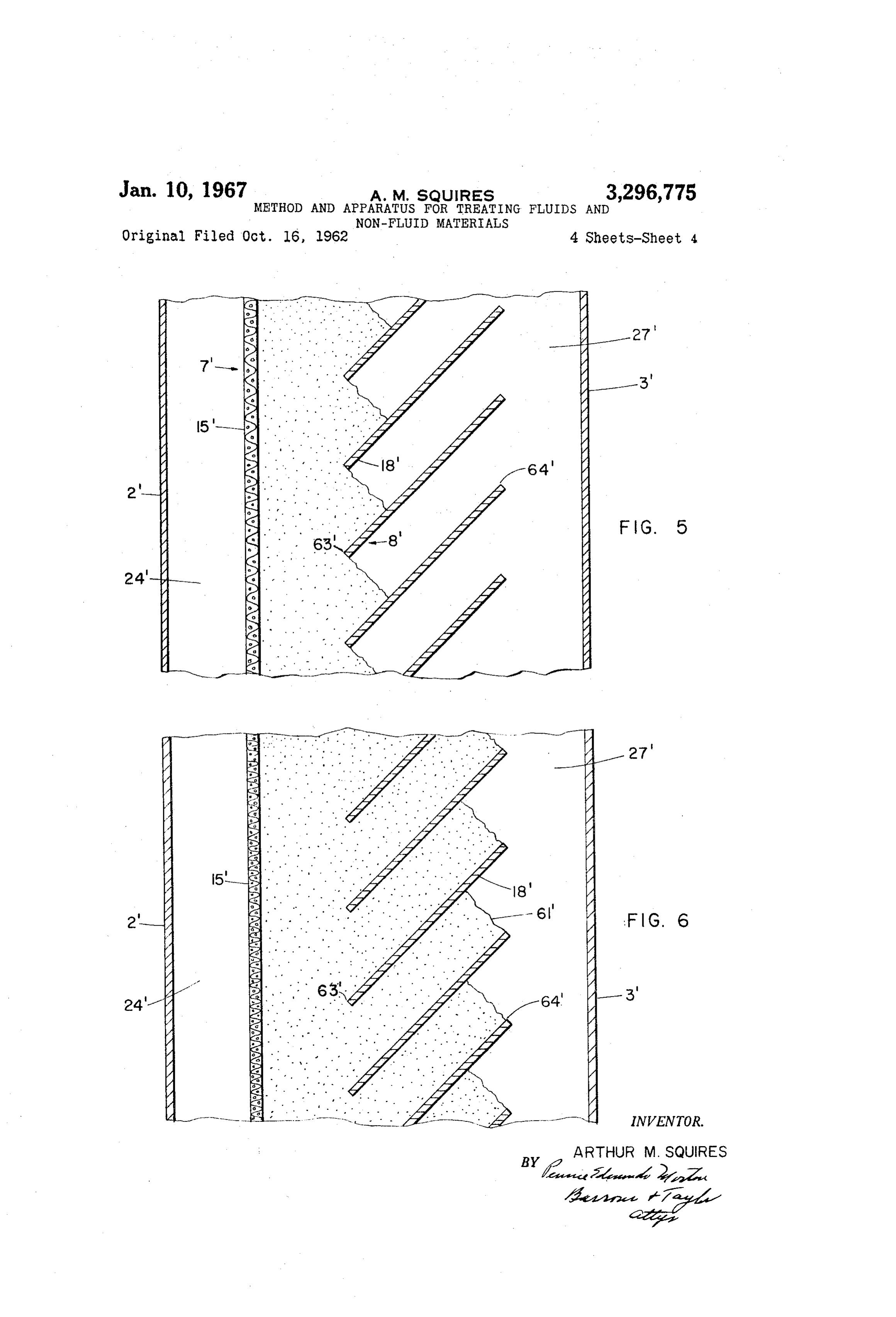
FIG. 4 is a graph illustrating the type of reverse flow conduits 42 and 41 form a passageway for the removal of needed to practice the invention; clean or treated gas from the loose surface contactor. FIG. 5 is an enlarged sectional elevation view of a por As shown schematically in FIG. 2 conduit 42 branches tion of a modified solids-gas contacting panel with the into lines 44 and 45. Line 44 has a valve 47 and connects sand in the initial fill position; 5 conduit 42 with the gas inlet of a blower 48. Line 45 FIG. 6 is a view of the panel of FIG. 5 with the sand connects conduit 42 with a gas tank 50, which is loaded in the operating position. with gas under pressure. A quick-opening valve 51 is The term granular material or sand as used herein and located in line 45 and controls flow of gas from tank 50 to in the claims refers to the physical characteristics of the conduit 42 as will be subsequently described. material making up the bed and includes any granular 10 Pressure gauge 53 is connected to and indicates the gas or particulate material suitable for practicing the in pressure in tank 50. Connected to the lower end of tank vention. The actual chemical composition of the gran 50 is a conduit 54 leading to a source of pressure P. ular material or sand to be used in a particular applica Valve 56 located in conduit 54 controls the admission of tion is at least in part dependent upon the process or treat gas from pressure source P to tank 50. A branch line 57 ment involved. For example, in practicing the invention 5 with a valve 58 is connected to conduit 54 intermediate for separatnig fly ash from gases, a well graded quartz tank 50 and valve 56 so that gas can be bled from tank sand might be desirable. Several ranges of well graded 50 if necessary.
quartz sand within the limits of 16-100 mesh have been In operation, the filter panel 1 is initially charged with tested and found satisfactory for this application. For granular material, with plugs 14, 32 and 36 in place, as gas-solids contact work carrying out a chemical reaction 20 shown. Plug 21 is removed, and granular material is fed in place of or in addition to mere mechanical filtering, through the opening in cover 20 of reservoir 19 to build the process would dictate the chemical composition of the up a bed of granular material between perforate walls 7 sand or granular material to be used in the bed. and 8 and to provide a supply of granular material in As illustrated in the drawing, the loose surface filter reservoir 19. Resting upon and separated by the inter panel 1 comprises a casing of rectangular cross-section posed supporting members or louvers 18 are transversely having opposed side walls 2 and 3 and opposed edge walls disposed, vertically spaced, superposed gas entry portions 4 and 5. A generally vertical bed of granular material 12 of the granular material bed 6 having free surfaces 61 6 is within the casing and retained by vertically extending inclined to the horizontal at the natural angle of repose extending spaced perforate walls 7 and 8. of the granular material, and exposed to gas passage 27. Perforate wall 7 consists of a wire mesh screen 15 ex 30 Louvers 18 are positioned so that the granular material, tending between the edge walls 4 and 5. Screen 15 is of as initially charged to the panel, will be retained by the the proper mesh to retain the granular particles while perforate wall 8; that is, the louvers 18 are positioned so allowing passage of gas through the bed without exces that a plane connecting the inner edge portion or heel 63 sive pressure drop. While a wire mesh screen is illus of each louver 18 with the outer edge portion or peak 64 trated, a series of spaced louvers or other types of per 35 of the subjacent louver is inclined to the horizontal at an forate walls designed to retain the sand bed while allow angle less than the angle of repose of the granular ma ing the passage of gas through the bed would be sat terial used in the filter bed. Or as stated more generally, isfactory. imaginary plane surfaces connecting heels 63 of louvers Perforate wall 8 comprises a series of inclined inter 18 with toes 64 of the respective subjacent louvers extend posed louvers or supporting members 18 mounted in Vene 40 above the respective imaginary plane surfaces commencing tian blind fashion extending outwardly from the bed to from heels 63 and extending outwardly and downwardly retain the granular material in place during the filtering toward passage 27 at the angle of repose of the granular operation. The perforations of the wall 8 are to be material making up the bed. When using the present in considered as being formed between respective heel por vention as a gas filter, it is preferable that the peak edges tions 63 of the adjacent louvers 18. of the louvers extend just slightly beyond the toes of the Perforate wall 7 and casing side wall 2 are spaced granular material surfaces in the initial fill position of the from one another to form with the casing edge walls 4 sand bed 2 as illustrated in FIGS. 1-3. and 5 a gas passage 24. Similarly, perforate wall 8 and In addition, although not necessary for carrying out the side wall 3 form with edge walls 4 and 5 a gas passage 27. invention in its broadest aspects, it is desirable that the Gas passages 24 and 27 are in communication with each louvers 18 be inclined to the horizontal at an angle greater other through the bed of granular material 6. than the angle of repose of the granular material to be Underlying the bed of granular material 6 is a bin used as the filter media in order to enable complete drain portion 9 having side walls 10 and 11 continuing down ing of the bed by gravity, if desired, by merely removing wardly from the respective perforate walls 7 and 8, and 5 5 plug 14.
inclined bottom walls leading to a drain outlet controlled During the filtering cycle, gas-inlet conduit 38 is con by plug 14. Similarly, underlying the gas passages 24 and nected to a source of untreated or dirty gas, and blower 27, respectively, are bin portions 30 and 34 having in 48 is operated to create a reduction in pressure at the clined bottom walls terminating adjacent outlets con outlet side of the panel through conduits 44, 42, 41 and trolled by drain plugs 32 and 36, respectively. As shown 60 gas passage 24. Alternatively, the incoming gas may be in the drawings the container has inclined bottom sur fed to the intake gas passage 27 under positive pressure faces 13 which provide the bottom walls for the respec from a blower or other means, rather than being induced tive bin portions. by the blower 48. The difference in pressure on opposite Contiguous with and continuing upwardly from per sides of the bed of granular material 6 causes the dirty forate walls 7 and 8 are upper side walls 16 and 17 gas to flow via conduits 38, 39 and gas passage 27 through which join edge walls 4 and 5 to form an overhead bin the bed of granular material 6 to the gas passage 24, con or reservoir 19. Reservoir 19 has a cover 20 with a duits 41, 42 and 44. The dirty gas first contacts bed 6 and material inlet controlled by a plug 21. most of the filtering takes place at the exposed free surfaces Gas passage 27 is connected to a gas-inlet conduit 38 61, that is, adjacent the gas entry portions of the filter by a generally triangular shaped adapter conduit 39. 70 panel, and particulate material carried by the gas de Conduit 38 is adapted to be placed in communication with posits and accumulates on surfaces 61, so that the par a source of untreated or dirty gas, such as exhaust gas ticles of dust and dirt are separated from the gas. from a furnace when the panel is used as a filter. Sim The gas to be treated is caused to flow through the ilarly, gas passage 24 is connected to a conduit 42 by a filter panel, that is, inwardly of the gas entry portions and outwardly from gas exit portions, until an accumulation generally triangular shaped adapter conduit 41. The of filtered particulate material builds up on surfaces 61.
Page 7
sufficiently as to adversely affect the pressure drop across There must be sufficient surge or acceleration sharply the filter panel. Then the flow of dirty gas is stopped, peaking to a high flow rate to create a shock wave act preferably by disconnecting blower 48 from conduit 42, ing through the bed to cause a mass movement of the such as by actuating valve 47. Sand or granular material. The almost immediately ap To clean the bed of granular material 6, valve 51 is plied intense flow preferably should be applied only long then quickly opened, and the sudden removal of a bar enough to move the outer surface portion of the bed rier between the relatively high gas pressure in tank 50 beyond the outer edges of louvers 18 the desired amount, and the relatively low pressure in conduits 45, 42, 41 and after which the intensity should be reduced sharply or cut gas passage 24 causes a shock wave of gas to travel off entirely. If the intense flow rate were applied for through the granular material in a direction reverse to O a longer period of time than necessary, a considerable the normal flow of gas during the treating process. The annount of the granular material bed would be lost, and volume and pressure of the gas initially contained in tank possibly the entire bed blown clear of the Supporting 50 are of a magnitude to effect a surge flow of gas through members. No values have been placed on the curves in the filter panel so as to move the sand or granular ma FIG. 4 since the minimum steady flow rate, and the surge terial in a mass toward gas passage 27. Since the gas flow pattern needed to carry out the invention are de entry surfaces 61 initially were substantially contiguous pendent on a great number of things including the particle with the outer edges 64 of supporting members 18, the size and characteristics of the sand or granular material mass movement of the granular material carries a portion forming the bed, the spacing and positioning of the sup of the granular material bed including the free surfaces porting members, the thickness of the bed and the na 61 and the filtered dust deposited thereon beyond the ture of the gas used to create the reverse surge. More outer edges 64, and gravity causes a spilling of this ma over, for a given installation, the shape of the curve neces terial from the supporting members 8. After the bed is Sary to afford adequate surge flow may vary within limits. cleaned, the cleaning cycle is repeated and dirty or un However, all suitable flow patterns will indicate the need treated gas is again passed through the panel. By reg for a Substantially instantaneous high intensity flow of ulating the intensity and volume of the reverse Surge flow gas to create a shock wave necessary to move the gran of gas, the amount of material removed from the outer lilar material in mass.
portion of the filter bed may be controlled, and thus it is Valve 5 is a quick opening valve so that the contents possible to regulate the amount of granular material re of the tank are placed in open communication with the moved from the bed. Optimum results are obtained when Sand bed Suddenly to provide the desired surge flow. the reverse surge flow causes a dense plug-like movement Were valve 51 to open slowly, the flow would not ac of granular material between adjacent louvers so that a celerate sufficiently to move the sand bed as previously neat slice is removed from each gas-entry face of the bed. described. In terms of the graph, the slope of the curve The surge flow of gas necessary in practicing the inven B must be steep so that a high flow rate occurs almost in tion is possible because of the compressible nature of gas. Stantaneously to act on the bed with an explosive force. When released, the compressed gas expands and acts with 35 It is preferred to employ a free surge method; that is explosive force on the granular material in the bed. the Valve 5 is opened for an indefinite period of time Not sharing this compressible nature, liquids are unsuit So that the tank 50 is freely vented during each surge able for carrying out the invention. flow. Hence tank 50 is of limited volume so that the The material removed from the gas entry portions falls high flow rate falls off quickly after valve 5 is opened. into bin portion 34 underlying gas passage 27. Bin por 40 While the free surge flow is preferred, the invention can tion 30 receives any material which may be carried be be carried out with a larger volume source or reservoir yond perforate wall 7 during filling of the sand bed or of gas under pressure being placed in communication during operation. with the clean side of the filter panel for a definite pre After the momentary high intensity reverse Surge foW determined period of time by opening and closing valve has been effected, fresh granular material will flow auto 51. Since the movement of the bed is caused primarily matically by gravity from the overhead bin 19 to replace by gas flow corresponding to the upper regions of curve the material which was removed from the filter panel, and B, gas flow corresponding to the lower portion of the the flow of gas to be treated is resumed. It is important curve, that is flow having little or no effect on movement that reservoir 9 be provided with additional granular of the Sand bed, need not be continued. The important material periodically so that fresh sand will always be 50 factor is to employ means producing an intense surge available to automatically replace the granular material flow of gas long enough to effect removal of the desired which is removed from the bed. Also, bin portions 38 amount of granular material.
and 34 need be emptied periodically to prevent an unde FIGS. 5 and 6 illustrate a modified loose surface con sirable buildup of material, in gas passages 24 and 27. tactor which has particular utility in gas-contacting fields in applications where the dirty granular material is ca 5 5 where maximum contact between gas and solids is desir pable of being readily cleaned, revivified or regenerated, able. The individual supporting members 8 illustrated, it might be desirable to freshen the dirty material removed are considerably wider than the previously described sup from the bed and reuse it in the bed. For example, porting members 18 so that the peak or outer portions of when practicing the invention as a dust collector for the the Supporting members are at least as high an elevation removal of fly ash from furnace gases, the dirty sand 60 as the heel or inner portions of the adjacent upper sup removed from bin 34 may be cleaned and recirculated to porting members. When the panel is initially charged the bed through reservoir 9. With granular material, as shown in FIG. 5, the peak or It must be emphasized that not just any reverse flow of ‘Outer edge 64 of each supporting member extends a con gas will accomplish the aforementioned result. FiG. 4 siderable distance beyond the toe of the free surface of illustrates a graph having two curves A and B. Curve the corresponding fluid entry portion. By producing a A, which is a broken horizontal line, indicates the mini number of reverse surge flows, similar to those previous mum steady flow rate at which a flow of gas causes ly described in conjunction with FIG. 4, the granular ma motion of the granular material bed surfaces in a typical terial will be moved into the operating position shown in installation. Curve B indicates a flow pattern affording FIG. 6. By having the Supporting members extend well adequate surge flow to practice the invention. The Sub beyond the toes of the respective free granular faces in stantially instantaneously applied rate of flow needed to the initial fill position, and moving the bed outwardly ad move the mass of granular material between adjacent jacent the outer edge portions of the respective support louvers, as shown by curve B, is appreciably greater than ing members, the gases to be treated will pass through a the minimum steady flow rate of curve A. A high in considerably longer path of granular material than in tensity Surge of gas for a short duration is required. 75 the FIG, 1 embodiment,
Page 8
It is highly desirable that the free granular material proceed inwardly beyond the point at which it can be surfaces be substantially contiguous with the outer edges removed by one or more surge flows of gas in the reverse of the supporting members throughout the width and direction. In some applications where the spent material height of the contactor. Having the free granular mate is to be removed as a product of the operation, only a rial surfaces substantially contiguous with the louver 5 portion of the layer need be removed during each clean edges throughout the width and height of the contactor ing cycle. This would ensure that the product removed assures a substantially uniform spillage of material from would have been completely reacted by the incoming gas all of the surfaces across the entire length of the bed with before it is removed from the bed. a minimum of expended power. Moreover, by having The foregoing description has been directed to a single the free granular material surfaces in the same relative 10 contactor panel to facilitate understanding applicant's in position after each reverse surge flow, it is easier to con vention. In an actual installation it might be desirable to trol the amount of spillage or the thickness of the slices have a number of contactor panels. For example, several removed from the bed through regulation of the intensity panels might be arranged in parallel, with adjacent panels and duration of the reverse surge flows. Also, the simi facing in opposite directions, and spaced from one an lar granular material levels between each pair of adjacent other to form gas passages therebetween. In this ar supporting members ensures that the gases to be treated rangement, the gas passages would be manifolded so that will have substantially the same duration and degree of alternate passages would be inlet passages to receive the contact with the granular material irrespective of where untreated or dirty gases, and the remaining alternate the gas enters the bed. passages would serve as outlet passages to carry away In the FIG. 1 embodiment, the granular material will 20 the clean or treated gases. Each gas passage would Serv assume the above described position in the initial fill posi ice two opposed contactor panels, either as an inlet or tion. In the FIGS. 5 and 6 embodiment the supporting dirty gas passage or as an outlet or clean gas passage. members 18' preferably are inclined to the horizontal at Also, an installation might be divided into a number of an angle less than the angle of internal friction of the sections whereby one or more sections could be subject granular material making up the bed so that material 2 5 to reverse surge flows while other sections simultaneously moved outwardly between adjacent supporting members are on line and effecting treatment of dirty gas or granular by reverse surge flows will not be dragged downwardly material. The principle of operation of such installation toward the interior of the panel by downward movement would be the same as described above. of the granular material in the interior of the bed occur It will be apparent that there has been provided a fluid ring after each surge flow. Were the inclination of the 30 Solids contactor of the counter-flow or counter-current Supporting members 18' steeper than the angle of internal type, since the fluid being treated is passed through the friction, when the granular material is moved in a mass contactor in one direction, and the granular material is outwardly toward gas passage 27" by a reverse surge flow passed from the contactor in a reverse or opposite direc of gas, the material moved outwardly in the lower portion tion. This arrangement provides for the removal of of the panel would be replaced by the granular material 35 material which has been subject to the greatest amount of between the Supporting members of the upper portion of untreated gas, so that the spent or used up material will the panel rather than from the overhead bin. However, be removed from the bed while allowing retention of the with the supporting members 18' inclined at an angle less clean granular material.
than the angle of internal friction, the sand moved out 40 The specific embodiments shown in the drawing and Wardly on the supporting members short of the outer described above are for illustrative purposes only and are edge portion 64’ during any reverse surge flow, will re not intended to limit applicant's invention, the scope of main there as long as the bed is charged with sand from which is embraced in the following claims. the overhead sand bin or reservoir, or until forced out I claim:
wardly and spilled from the supporting members by a 1. The method of treating at least one of a granular Subsequent reverse surge flow of gas. And when granular material and a fluid by contact with one another compris material is removed by a subsequent reverse flow of gas, ing arranging the granular material in a bed having a it will be replaced by material from the overhead bin and plurality of transversely disposed, upwardly spaced, fluid not from material between supporting members in the entry portions separated and supported by interposed upper portion of the panel. Hence, the free granular members having outer and inner edges with respect to material Surfaces in the FIG. 6 modification will be main said bed, said bed having fluid exit portions spaced from tained substantially contiguous with the outer edges of said inner edges, passing fluid through said fluid entry Supporting members 18' throughout the operation of the portions and outwardly from the fluid exit portions of loose surface contactor. the bed, and thereafter causing a surge flow of a gas In use of the loose surface contactor solely as a dust sharply peaking substantially above and substantially im collector, the particulate matter is separated at the gas mediately declining below the minimum steady flow rate entry surfaces of the bed with little penetration of the at which the flow of gas causes motion of the granular filtered material into the sand mass. Therefore, in using material and in a reverse direction through said fluid the invention for dust collection purposes, a narrow bed entry portions to remove a portion of the granular mate of granular material such as the FIG. 1 modification is rial from the bed.
preferable due to the lower power requirements. 2. The method of treating a fluid by contact with a While the modification of FIGS. 5 and 6 could be used granular material which comprises arranging the granular as a dust collector, this loose surface contactor is par material in a bed having a plurality of transversely dis ticularly desirable where it is advantageous for the gas posed, upwardly spaced, fluid entry portions separated to flow through a long path of granular material to pro and Supported by interposed members having outer and vide a maximum amount of countercurrenticity between 65 inner edges with respect to the bed of granular mate the gas and the granular material. For example, in some rial, said bed having fluid exit portions spaced from said gas contacting applications where the gas reacts with the inner edges of the supporting members, flowing the fluid granular bed, while initially reacting with the outer sur to be treated through the fluid entry portions of the bed faces of the gas entry portions, some of the reaction takes and outwardly from the fluid exit portions of the bed, place inwardly of the outer surfaces, and a growing layer causing a Surge flow of gas sharply peaking substantially of spent material will appear in the bed, commencing above and substantially immediately declining below the from the outer surfaces. The spent or used up material minimum steady flow rate at which the flow of gas causes should be removed before the layer of spent material motion of the granular material and in reverse direction extends to the inner edges or inner portions 63' of the through said fluid entry portions to move the granular supporting members so that the spent material does not material in a mass toward the outer edges of the sup
Page 9
porting members and to cause a portion of the granular spaced from said inner edges and substantially contiguous material to spill from the outer edges of the supporting with said outer edges of the Supporting members. members, and Supplying fresh granular material to the bed 6. A gaseous fluid-Solid contactor comprising a pair of in an amount Substantially equal to that spilled over the upwardly extending horizontally spaced-apart perforate outer edges of the supporting members. retaining walls, a gaseous fluid inlet compartment ad 3. The method of treating a gas involving the separa jacent and in communication with the perforations of a tion and removal of particulate material by means of a first of the perforate walls, a gaseous fluid outlet compart filter of granular material which comprises arranging the ment adjacent and in communication with the perforations granular material in a filter bed having a plurality of of the second of the perforate walls, closure means about transversely disposed, upwardly spaced, gas entry portions O the space between the first and second perforate walls separated by interposed members having outer and inner closing Said space against the passage of gas except edges with respect to the filter bed, said filter bed having through the perforations of said perforate walls, feed gas exit portions spaced from said inner edges, flowing the means for Supplying a loose solid particulate material gas to be treated through said filter bed by passing it in into the Space between the perforate walls, a plurality of wardly through the gas entry portions and outwardly 5 particulate-material Support members each adjacent a per from the gas exit portions to separate and accumulate par foration of said first perforate wall, said particulate-ma ticulate material at the outer surfaces of the gas entry terial Support members being arranged to extend out portions, stopping the flow of gas to be treated, causing Wardly and upwardly from below their adjacent perfora a reverse surge flow of gas sharply peaking substantially tions and into the inlet compartment to support and ex above and substantially immediately declining below the 20 pose to the inlet compartment a plurality of free surfaces minimum steady flow rate at which the flow of gas causes of particulate material, an inlet for admitting a gaseous motion of the granular material and through the gas entry fluid into the inlet compartment for passage into the free portions in a reverse direction to cause the granular ma Surfaces and through the particulate material to the out terial to move in a mass in said reverse direction to cause let compartment, an outlet for discharging gaseous fluid a portion of the granular material including said outer 25 from the outlet compartment, means for periodically ef Surfaces and accumulated particulate material to spill fecting a mass movement toward the inlet compartment from said outer edges, and also supplying fresh granular of at least those portions of the particulate material in material to the upper portion of the filter bed. cluding said free surfaces and which are retained on said 4. A method of contacting fluid and granular material Supporting members, said mass-movement means com with each other to effect treatment of at least one of them 30 prising:
comprising arranging granular material in a bed having (1) a Source of gas under pressure; a plurality of transversely disposed, upwardly spaced fluid (2) means for effecting a sudden discharge of gas from entry portions separated by interposed supporting mem the pressure source into the outlet compartment and bers having outer and inner edges, said fluid entry portions 35 against the particulate material at a sharply peaking having fluid entry faces Substantially contiguous with said rate of gas flow having a peak value substantially in outer edges, said bed having fluid exit portions spaced excess of the minimum steady flow rate at which a from Said inner edges, flowing fluid through the fluid entry tly of gas causes motion of the particulate mate portions of the granular material bed and outwardly from Tal;
the fluid exit portions to effect treatment of one of said 40 (3) Volume control means for limiting the quantity of fluid and granular material, causing a surge flow of gas gas discharged into the outlet compartment to pro sharply peaking substantially above and substantially im vide an immediate decline in the rate of gas flow mediately declining below the minimum steady flow rate following the peak rate to control the quantity of at which the flow of gas causes motion of the granular particulate material displaced from the material Sup material and in a reverse direction through the fluid entry port members; and portions to cause a portion of the granular material at the means for discharging from the inlet compartment mate gas entry faces to move in said reverse direction beyond rialCaS which is displaced thereinto by the mass movement Said outer edges of the supporting members to be dis placed from Said bed, Supplying fresh granular material to 7. A gaseous fluid-solids contactor as set forth in claim Said granular material bed to replace the displaced mate 6 which said feed means includes a fresh granular mate rial at the fluid exit portion and to restore the granular rial reservoir, means for maintaining a bed of material in material in the fluid entry portions of the bed with its the Space between the perforate walls. fluid entry faces substantially contiguous with said outer 8. A gaseous fluid-Solids contactor as set forth in claim edges of the Supporting members. 6 wherein the individual Supporting members are inclined 5. A method of treating a gas by contact with granular to the horizontal at an angle less than the angle of inter material which comprises arranging granular material in a nal friction of the granular material, and the outer portion bed having a plurality of transversely disposed, upwardly of each supporting member being at least as high as the spaced gas entry portions separated by interposed Sup inner portion of the Superjacent supporting member. porting members having outer and inner edges, said gas 9. A gaseous fluid-solids contactor as set forth in claim entry portions having free surfaces spaced from said in 6 wherein the mass movement means comprises a tank ner edges a substantial distance and contiguous with said 60 having gas at a predetermined volume and pressure to outer edges, said bed having gas exit portions spaced effect the desired movement of granular material when from said inner edges, flowing the gas to be treated placed in open communication with the bed, valve means through the gas entry portions of the bed and outwardly for placing the tank in open communication with said from the gas exit portions to effect treatment of the gas, granular material bed, and means for interrupting said causing a surge flow of gas sharply peaking Substantially fluid passage means while the tank is in communication above and substantially immediately declining below the with the granular material bed. minimum steady flow rate at which the flow of gas causes 10. A gaseous fluid-solids contactor as set forth in claim motion of the granular material and through the gas entry 6 wherein the outer portions of the free granular mate portions of the bed in a reverse direction through the gas 70 rial surfaces are substantially contiguous with the respec entry portions to cause a portion of the granular material tive outer portions of the supporting members. at the gas entry faces to flow outwardly and downwardly 11. A gaseous fluid-solids contactor as set forth in claim under the force of gravity, supplying fresh granular ma 10 wherein the supporting members are positioned so terial to said bed to replace the displaced material and that the free granular material Surfaces extend from ad restoring the gas entry portions with their free surfaces 75 jacent said inner portions of each of the supporting mem
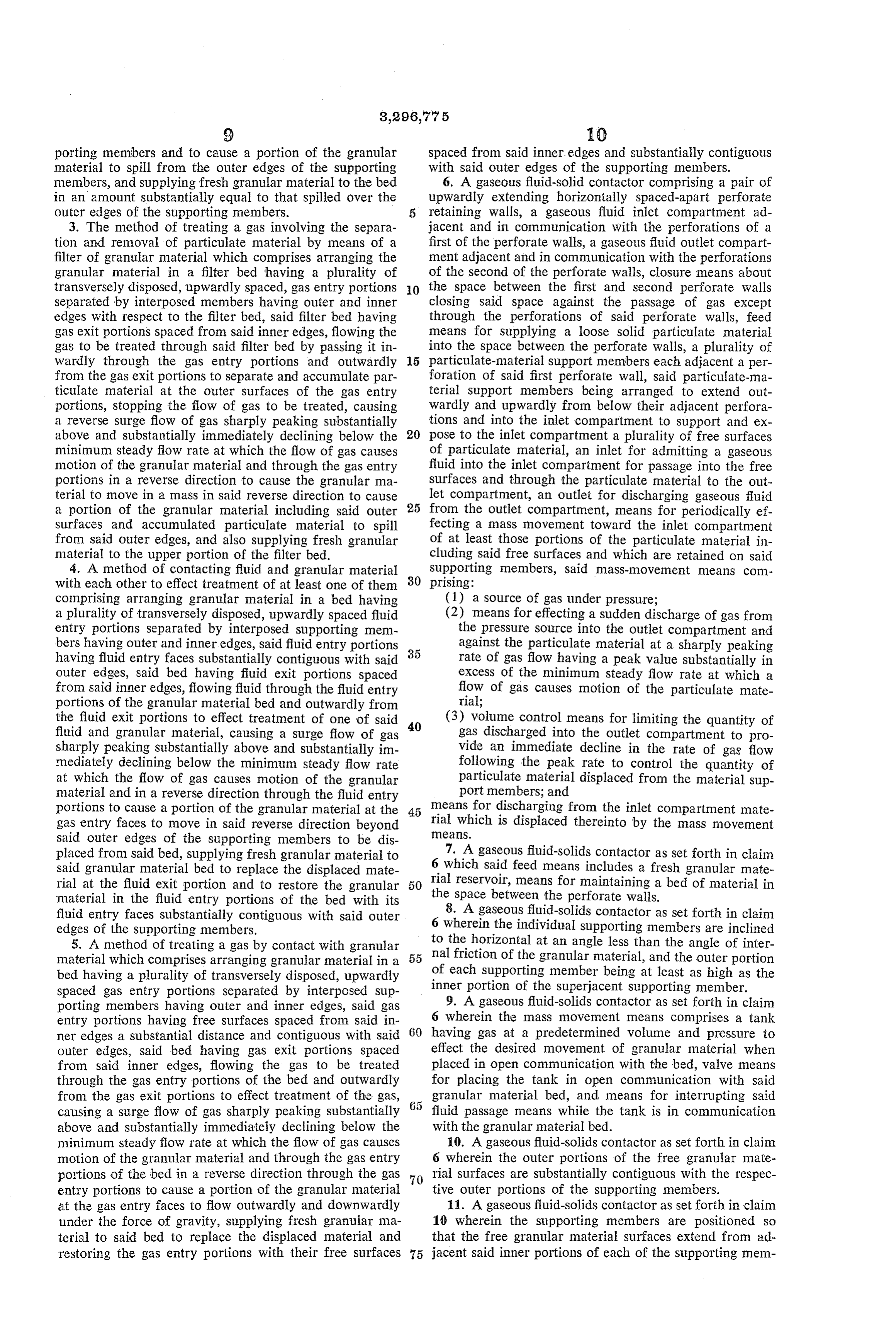
Page 10
bers to substantially contiguous with the outer portions of 2,493,356 1/1950 Mercier et al. ------ 55-474 X the respective subjacent supporting members. 2,521,195 9/1950 Wheeler ----------- 55-390 X 12. A gaseous fluid-solids contactor as set forth in claim 2,559,784 7/1951 Moore -------------- 210-80 10 wherein the individual supporting members are in 2,780,363 2/1957 PeW ---------------- 210-82 clined to the horizontal at an angle less than the angle 3,030,798 4/1962 Lichtenfela -------- 55-386 X of internal friction of the granular material making up 3,093,465 6/1963 Latta -------------- 55-34 X the bed and the supporting members are of sufficient width FOREIGN PATENTS so that the free granular material surfaces in the operat A. 26,145 4/1923 France. ing position of the contactor are located outwardly a sub 899,920 9/1944 France. stantial distance from their respective initial fill positions. O 381,500 5/1924 Germany.
References Cited by the Examiner 419,76410/1925 Germany.
UNITED STATES PATENTS 515,188 12/1930 Germany.
290,928 12/1883 Rew ---------------- 55-479 5 522,573 4/1931 Germany. 989,665 4/1911 Tixier ------------ 210-268 X 55,928 4/1911 Switzerland. 2,287,983 6/1942 Gavett ----------- 210-268 X REUBEN FRIEDMAN, Primary Examiner.
2,293,113 8/1942 Carney ----------- 55-474 X D. E. TALBERT, JR., Assistant Examiner.
Page 11
UNITED STATES PATENT OFFICE
CERTIFICATE OF CORRECTION
Patent No. 3, 296,775 January 10, 1967 Arthur Morton Squires
It is hereby certified that error appears in the above numbered pat ent requiring correction and that the said Letters Patent should read as corrected below.
Column l, line 33, for 'Venetion' read a - Venetian - - ; column 2, lines 17 and 18, for 'particulate material' read - - particulate-material - - ; line 30, for 'three' read -- free - -; line 33, for "pressures' read - - pressure - -; column 3, line 16, for 'separatnig' read -- separating -- ; line 29, strike out 'extending'; column 10, line 50, for 'reservoir," read -- reservoir - - .
Signed and sealed this 24th day of October 1967.
(SEAL)
Attest:
Edward M. Fletcher, Jr. EDWARD J. BRENNER Attesting Officer Commissioner of Patents
Provenance
- Collection
- Cited prior art
- Original PDF
- patentimages.storage.googleapis.com →
- Filed
- 1965-10-04
- Pages
- 11
- Method
- pdftotext (the PDF's own text layer) + pdftoppm 300dpi page scans
- Source
- Google Patents bibliographic record
- Granted
- 1967-01-10
- Inventors
- Squires Arthur Morton
- Transcribed from
- patentimages.storage.googleapis.com →