patent · US3254695
Diffusion burner
7 June 1966
Page 1
Drawing sheet — no readable text.
Page 2
United States Patent Office 3,254,695 Patented June 7, 1966
plement the initial oxygen insufficiency, will heat the gasi 3,254,695 fying surface directly or by radiation in order to maintain DFFUSON BURNER it at the desired preheating temperature. The supply of Willi Brödlia, Radolfzeller Str. 56, Allensbach the additional air may come simply from the atmosphere (Bodensee), Germany and/or may be brought in through special conduits.
Claims priority, application Germany, Nov. 29, 1960, The invention is applicable to oil burners of both the B 60,275 low-pressure and the high-pressure type. The first type, 6 Claims. (C. 158-4) normally designed for a capacity of 50-500 grams of fuel oil per hour, utilizes a generally concentric nozzle from
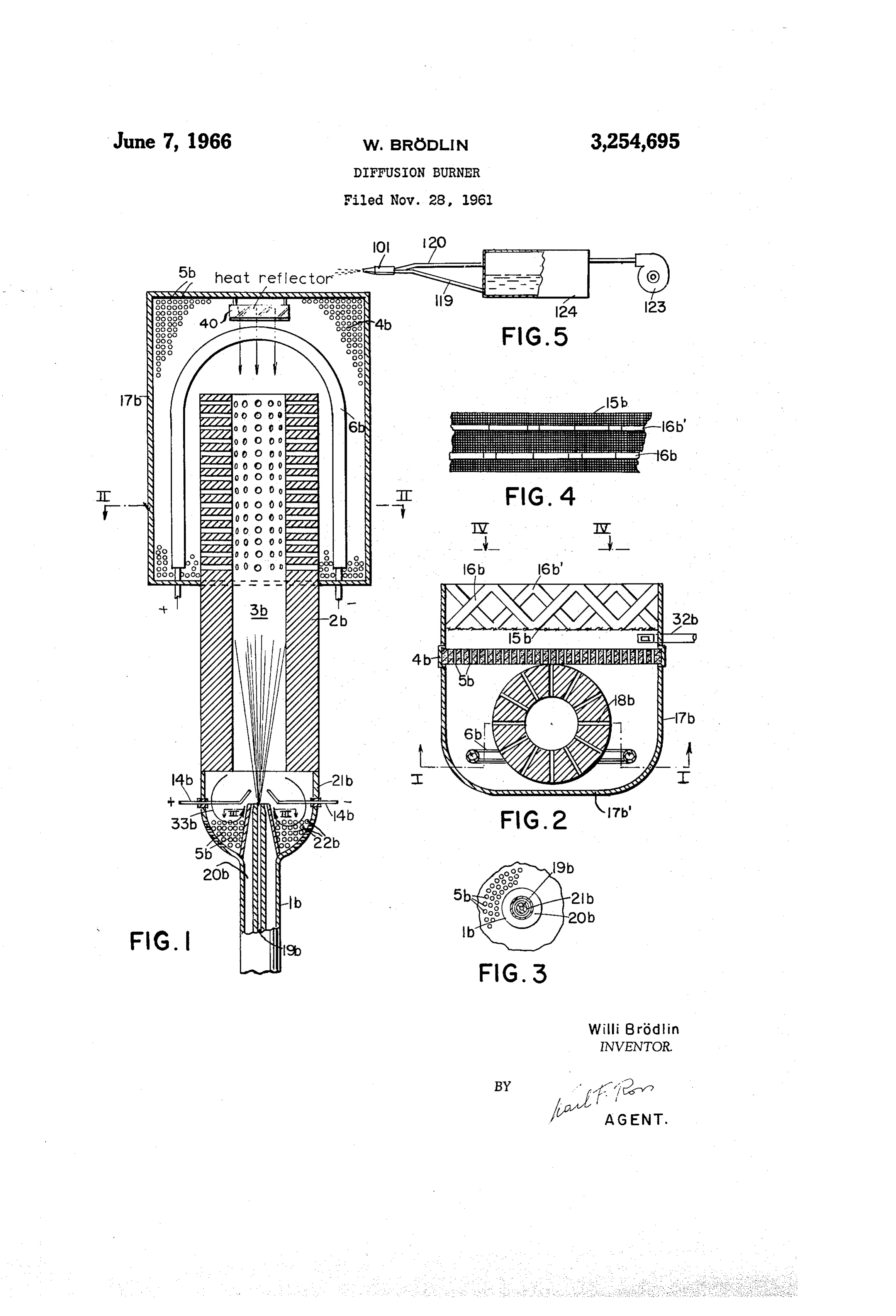
My present invention relates to a diffusion-type burner 0 which oil under a pressure of, for example, about 0.5 to for the combustion of liquid hydrocarbons such as fuel 1 atm. gauge is discharged together with air in a quantity oils. amounting to approximately 4-6% of that required for It is known to provide oil burners with gasifying sur combustion. The second type, usually with a capacity faces, formed for example by curved deflection plates, upwards of 600 grams of fuel per hour, has a nozzle against which an injected fuel/air mixture is directed in 5 from which oil alone is discharged at a gauge pressure of, order to promote the breakup of the liquid fuel into small say, 7-22 atm. while air is being supplied by a separate droplets. In the past, however, such burners generally blower. Either system is adaptable for use with my in exhibited a tendency of burning with a noisy, soot-produc vention so long as the air intake remains short of that ing yellowish flame so that, in those instances where this required for complete combustion. type of combustion was not desired, burners utilizing more 20 The heat necessary for maintaining the gasifying sur expensive fuels such as coal gas were given preference. face at its elevated temperature may be initially supplied In my copending application Ser. No. 834,245, filed by various means. Thus, an electric heating element may August 17, 1959, now abandoned, I have disclosed a burn be temporarily energized at the start of operations, or er construction and a method of operation whereby a type combustion may be initiated first within the diffusion of combustion similar to that of gas burners could be 25 chamber itself with a supply of additional air which is realized, the improvement residing essentially in the sep later cut off. A partial combustion with resulting decom aration of the larger droplets from the mixture prior to position of the hydrocarbons may also be continuously combustion and a further comminution of these droplets maintained at the chamber entrance. with reintroduction thereof into the injected stream. The invention will be further described with reference An object of my present invention is to provide an to the accompanying drawing in which: alternate solution to the problems stated above. FIG. 1 is an axial sectional view of an embodiment of A more particular object of the invention is to provide the present invention taken substantially on the line I-I of a highly economical method of operating an oil burner FIG. 2;
in such manner that combustion can be maintained not FIG. 2 is a section taken on the line II-II of FIG. 1; only with a so-called silent, soot-free blue flame but also, 35 FIG. 3 is a detail view taken on the line III-III of if desired, with distinct infrared-radiation characteristics. FIG. 1:
A further object of this invention is to provide an im FIG. 4 is a fragmentary view taken on the line IV-V proved burner adapted to be operated in the manner in of FIG. 2; and . " dicated above. FIG. 5 schematically illustrates an attachment for sup I have discovered, in accordance with this invention, 40 plying an air/fuel mixture to the burner of the preceding that the drawbacks of conventional constructions are large- . figures.
ly traceable to the fact that the fuel/air mixture initially The burner of FIGS. 1-4, which is particularly adapted admitted into the diffusion chamber contains an excess of for use as an emitter of infrared radiation, comprises a air which escapes unutilized into the atmosphere and dis nozzle 1b with a central fuel channel 19b and an external sipates a substantial part of the developing combustion air channel 20b concentrically surrounding the former. heat without useful effect. The discharge end of the nozzle is aligned with an outer A feature of the instant invention resides, therefore, in (i.e. lower) extremity of a tubular duct 2b whose interior the operation of a diffusion-type oil burner in such man 3b constitutes part of a diffusion chamber; the other (i.e. ner that a fuel/air mixture undersupplied with oxygen, preferably falling short by about 30% of the oxygen 50 aupper) extremity of duct 2b projects into the interior of hood 17b which encloses the remainder of the diffusion quantity stoichiometrically required for combustion, is ad chamber of this burner and has an imperforate curved mitted into a diffusion chamber and is heated therein by rear wall. 17b. A starting heater 6b is disposed within contact with a hot gasifying surface which may, if desired, also serve as a deflector to promote the dispersion of the the hood 17b adjacent the inserted upper end of duct 2b liquid stream into minute particles. . 55 which acts as an atomizer and forms a cylindrical flow The gasifying surface is advantageously maintained at guiding Surface. In order to increase the effective sur a temperature of approximately 500 to 550° C. The gas face area, duct 2b is provided in its inserted portion with ified fuel/air mixture, whose fuel particles at this stage a large number of radial bores 18b; these bores may, how may have reached the consistency of an aerosol (i.e., may ever, be omitted particularly in the case of larger installa be capable of floating in stationary air), is then discharged 60 tions. Duct 2b is preferably made of a material of good in a multiplicity of fine jets through a perforated boundary thermoconductivity, e.g. a metal, and as shown is de wall of the diffusion chamber; this boundary wall is so signed with relatively thick walls. positioned that a flame developed at its exterior, i.e., after A perforated plate 4b of ceramic material forms a the jets have been contacted with additional air to sup front or boundary wall of the hood 17b, parallel to the
Page 3
ors
s 4.
axis of duct 2b, and is provided with a multiplicity of open-topped upper portion projecting from below into Said passages 5b which are preferably very small pores with chamber, said duct being imperforate below said cham a diameter of 1 mm. or less. A fine-mesh radiation ber and provided with a multiplicity of radial bores screen 15b, made from a nonoxidizing alloy, is positioned throughout said upper portion thereof, injector means for just outside the plate 4b with a slight spacing therefrom; admitting into said chamber through said duct a flow of this screen is supported by a series of flat bracing strips combustible liquid hydrocarbons directed into contact 16b, 6b' extending generally perpendicularly to it. Ad with said surface, intake means adjacent said injector ditional combustion air may, if desired, be admitted into means for admixing with said flow a Supply of air having the region beyond plate 4b by means here illustrated as an oxygen content which falls short of the stoichiometric a conduit 32b. O quantity required for the combustion of said hydrocar The connection between nozzle b and the outer end bons, means inciuding said boundary wall preventing the of duct 2b is formed by an apertured cap 21b having per admission of additional oxygen into said chamber, and forations 22b. These perforations, whose effective over means including said boundary wall for preheating said all area may be adjustable by means not further illustrated, flow in its passage along said surface to maintain said serve for the admission of additional air into the region 5 flane by facilitating the ignition of streams of combustible just ahead of the duct 2b, it being understood that the air/hydrocarbon mixture emerging from said wall through total air quantity from channel 20b and perforations 22b said perforations.
will be short of that required for complete combustion of 2. A burner according to claim 1 wherein said cham the fuel injected via channel 19b, as previously explained. ber comprises a hood, said duct being provided with an The air and fuel streams injected by the nozzle may be 20 extremity opening into said hood, said injector and in under a pressure of about 0.1-0.5 atim. gauge (preferably take means being positioned at a location of Said duct not more than 0.2 atm. gauge). The wall thickness of remote from said extremity, Said boundary Wall forming cap 21b is very limited for the purpose of thermally in part of said hood.
sulating the hot duct 2b from the nozzle ib. 3. A burner comprising a diffusion chamber provided In operation, the duct 2b should be maintained at a 2 5 with a boundary wall having a multiplicity of perforations, temperature of at least 200° C., preferably 500-550° C. atomizer means forming a generally cylindrical flow-guid The flame developed in front of plate 4b at the grid 15b ing surface in said chamber with an axis Substantially will generally radiate enough heat toward the inserted up parallel to said wall and positioned to be heated by radiant per end of the duct to maintain it at the desired tempera energy emitted by said wail upon the existence of a fame ture level, a heat reflector 40 being provided at the top at the exterior of said wall, a significant part of said upper of hood 7b to assist in the action by directing heat rays portion being separated from Said boundary wall by a from the region of plate 4b toward the nozzle lib, as shown Substantially empty space enabling the direct passage of in FIG. 1; additionally, however, a partial combustion radiant heat from said wall to said surface, injector means may be maintained within cap 21b which will give rise for admitting into said chamber through said duct a flow to an annular flame forming a vortex around the nozzle of combustible liquid hydrocarbons directed into contact mouth as indicated by the arrows 33b. This fame, Whose with said surface, intake means adjacent said injector extent is limited by the underSupply of OXygen, causes a means for admixing with said flow a supply of air hav decomposition and partial oxidation of the injected fuel ing an oxygen content which falls short of the stoichio into carbon monoxide and hydrogen which, upon their 40 netric quantity required for the combustion of said hy subsequent combustion at the grid 15b, gives rise to a drocarbons, means including said boundary wall prevent particularly quiet flame without soot. The burner shown ing the admission of additional oxygen into said chamber, in FIGS. 1-4 can, therefore, be operated without a flue and means including said boundary wall for preheating for the escape of combustion gases. The partial com said flow in its passage along said Surface to maintain bustion within cap 21.b can be brought about by suitable said flame by facilitating the ignition of streams of com ignition means such as a pair of electrodes 14b. bustible air/hydrocarbon mixture emerging from said wall FIG. 5 shows an attachment for Supplying fuel and air through said perforations, said chamber comprising a to a nozzle, here designated 501, which is representative hood, said atomizer means comprising an elongated duct of the nozzle shown in the preceding figures. An oil provided with an extremity opening into said hood, said reservoir 24 is connected by conduits 19 and 120 to injector and intake means being positioned at a location the corresponding channels of nozzle 101. Air under 50 of said duct remote from said extremity, said boundary pressure is delivered to reservoir 24 by a blower 23. wall forming part of said hood, said hood being further Part of this air is passing out of the reservoir through provided with fine-mesh screen closely spaced from said conduit 129 while the remainder creates sufficient pres boundary wall and positioned externally thereof. sure to drive oil at the desired rate through the channel 4. A burner comprising a hood-shaped diffusion cham 19. The oil may, of course, be supplied continuously ber provided with a curved solid rear wall and a per or intermittently from a suitable source not shown. The forated front wall, an elongated upright duct with an pressure of blower 123 may be of the order of 0.1-0.3 said open-topped upper portion projecting from below into atm. gauge. chamber, a significant part of Said upper portion being separated from said front wall by a substantially
My invention is not limited to the specific embodiment empty described and illustrated but may be realized in various 60 space enabling the passage of radiant heat from modifications except as otherwise limited by the appended said front wall to said duct through said chamber, injec tor means for admitting into the lower end of said duct claims.
below said chamber a flow of combustible liquid hydro 1. A burner comprising a diffusion chamber provided carbons directed upwardly into said chamber, intake means adjacent said injector means for admixing with with a boundary wall having a multiplicity of perfora 65 said tions, atomizer means forming a generally cylindrical falls flow a supply of air having an oxygen content which short of the stoichiometric quantity required for the flow-guiding surface in said chamber with an axis Sub combustion of said hydrocarbons, and means including stantially parallel to said wall and positioned to be heated said first wall for preheating the flow of air/hydrocarbon by radiant energy emitted by said wall upon the existence 70 mixture in said duct.
of a flame at the exterior of said wall, a significant part of 5. A burner according to claim 4, further comprising said surface being separated from said boundary wall heat-reflection means for directing heat from the region by a substantially empty space enabling the direct passage of said front wall toward said injector means. of radiant heat from said wall to said Surface, Said aton 6. A burner according to claim 4 wherein said duct izer means including an elongated upright duct with an is imperforate below said chamber and is provided with
Page 4
a multiplicity of radial bores throughout said upper por 2,630,168 3/1953 Farrell -------------- 158-53 tion thereof. 2,869,626 1/1959 Sherman ------------- 158-4
References Cited by the Examiner 3,084,736 4/1963 Mentel et al. -------- 158-14 UNITED STATES PATENTS 5 3,124, 193 3/964 Klein ------------ 158-114 X
FOREIGN PATENTS
1,676,501 7/1928 Moors -------------- 158-53 1,263,387 5/961 France.
1,847,020 2/1932 Parker et al. ---------- 158-5 10 FREDERICK L. MATTESON, JR., Primary Examiner. 1933,044 10A 1933 Cannon ------------ 58-4X JAMES W. WESTHAVER, Examiner.

Provenance
- Collection
- Cited prior art
- Original PDF
- patentimages.storage.googleapis.com →
- Filed
- 1961-11-28
- Pages
- 4
- Method
- pdftotext (the PDF's own text layer) + pdftoppm 300dpi page scans
- Source
- Google Patents bibliographic record
- Granted
- 1966-06-07
- Inventors
- Brodlin Willi
- Transcribed from
- patentimages.storage.googleapis.com →