patent · US2532214
Protective apparatus for combustion systems
28 November 1950
Page 1
Drawing sheet — no readable text.
Page 2
Drawing sheet — no readable text.
Page 3
Patented Nov. 28, 1950 2,532,214
UNITED STATES PATENT of FICE
PROTECTIVE APPARATUS FOR,
COMBUSTION SYSTEMS
Walter J. Willenborg, Weehawken, N.J., assignor to Jabez Burns & Sons, Inc., New York, N. Y., a corporation of New York
Application February 9, 1946, Serial No. 646,511
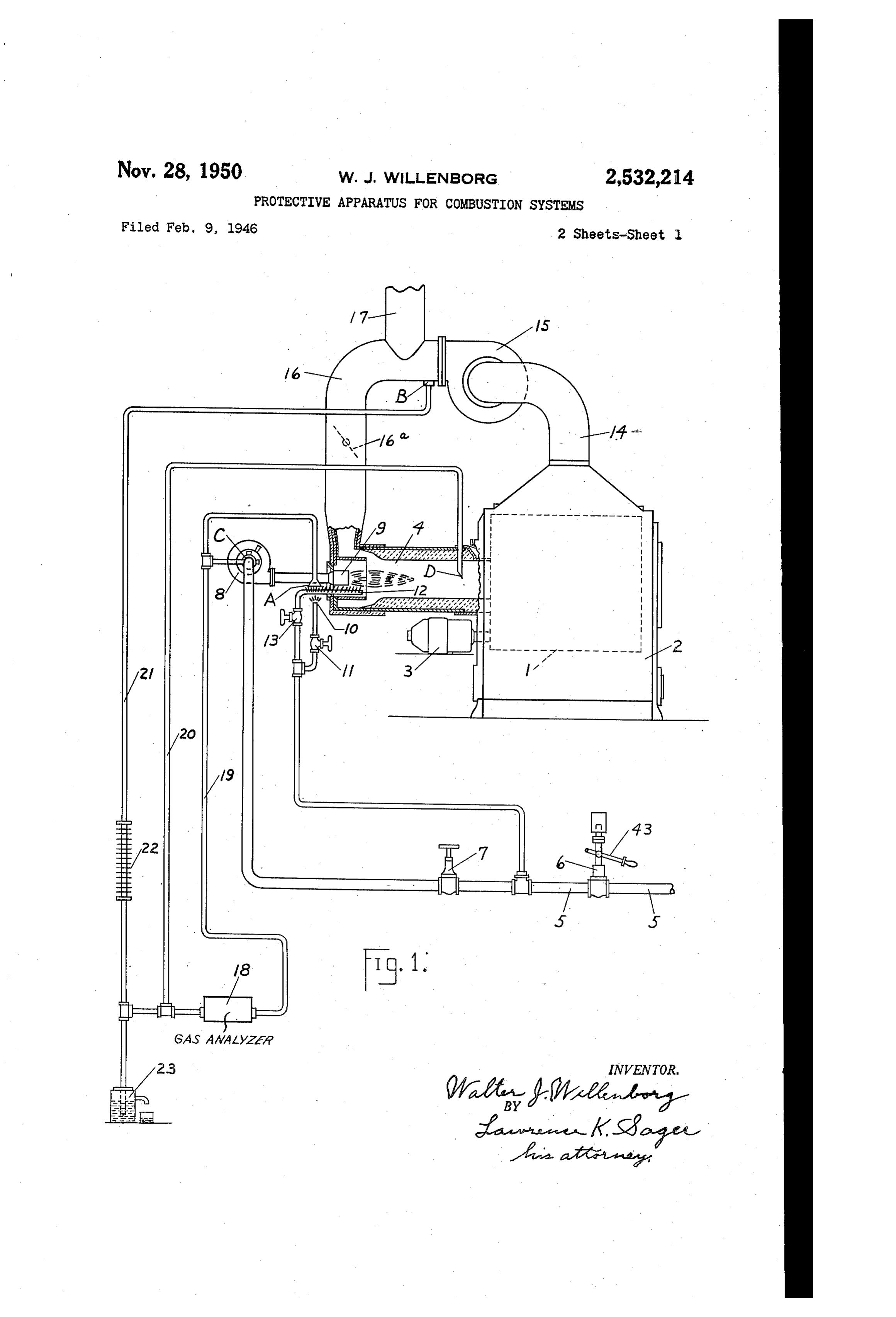
This invention relates to protective and indi air and gases pass to a burner nozzle 9 extend cating apparatus for various types of combustion ing within the combustion chamber or muffle 4. systems such as roasters for coffee and the like, A pilot light 0 is shown near the entrance to bake ovens and other combustion systems where the combustion chamber and is supplied by a it is possible for gases and vapors to accumulate 5 pipe Connection, having a shut off valve it, from in the combustion chamber and in other parts the main Supply pipe 5 at a point between the of the system which may create a dangerous Con Valves 6 and . A runner light 2 extends from dition. The invention also relates to the method near the pilot light to near the burner nozzle and of obtaining continous samples of the gases from is provided with a stop valve 3 in its connec different parts of the systems during operating tion to the pilot light connection. An outlet and shut down conditions, to the determining. pipe extends from the roasting chamber to of the condition of the gases and to the indica a power driven fan 5 and the outlet from the tion and control of parts for protective purposes fan is connected by a pipe 6 to the combustion and for the efficient operation of the systems. chamber for recirculating a portion of the pro One object of the invention is to automatical ducts of combustion through the system. A ly cut off the fuel supply upon the approach to damper 6d. is in the pipe 6. A vent pipe a dangerous condition and thereby prevent the to atmosphere from the pipe 6 permits the possibility of an explosion by continued Opera eScape of excess gases.
tion. Another object is to indicate to the Opera During normal operation such a system is tor the condition of the gases in the combustion free from danger owing to the low content of chamber so that he may know whether he is ob Oxygen in the heated gases which is insufficient taining the most efficient combustion during Op to Support combustion. However, unburnt gases eration and the extent of any departure there Inay accumulate in the system from various ab from. If incorrect he may then adjust the mix normal conditions during operation or during ture of air and fuel to proper proportions. A 25 shut down and if the oxygen content should then further object is to show the condition of the rise by admission of external air or otherwise, an gases in the system during shut down so that if unSafe explosive mixture may result. an undesirable or dangerous condition exists, the By the present invention samples of the gases System may be purged before starting up. An from various parts of the apparatus are trans other object is to provide continuous indications 30 mitted to an analyzer which responds to changes to the operator of the condition of the gases in in the condition of the gases for indication of the various parts of the System not only during their condition and for affecting controlling operation but also during shut down. These means to anticipate and avoid any danger when and other objects and advantages will be under a dangerous condition is being approached. stood from the following description and accom In Fig. 1 the analyzer 8 is generally indicated panying drawings which show a preferred em and is later explained. From its right-hand end bodiment as applied to a roasting machine sup a pipe connection 9 extends to an open end plied with illuminating gas as the fuel. near the pilot light to at location A and also to Fig. 1 is a Schematic showing of a coffee roaster an Open end at the intake of the mixer 8 at loca of known form in which the products of com tion C. From its left-hand end a pipe con bustion are recirculated and to which this in nection 20 extends to an open end within the provement is applied; and Fig. 2 is a diagram combustion chamber or muffle 4 at location D. showing the electric controlling and responsive A pipe connection 2 also extends from the left devices. hand end of the analyzer to the lower side of Referring to Fig. 1, a perforated roasting cy the recirculating pipe 6 near the exhaust from inder is indicated within an enclosing casing 2. the recirculating fan 5 at location B. A por The cylinder is rotated by an electric motor 3 tion of the pipe 2 contains a means 22, such as shown outside the Casing. An intake for the a pipe with a series of outwardly extending ribs gases of combustion to the roasting casing or or flanges, for cooling the gases to reduce the chamber is shown as a muffle 4 in which the burn moisture content before passing into the analyzer. er is located. The supply of the fuel, illuminat The pipe 2 has a downward extension entering ing gas in this instance, is from a supply pipe a receptacle 23 for receiving the excess moisture. 5 having a main control valve 6 and a shut off This receptacle has an overflow outlet, the end Valve 7, to an air mixer 8. This air mixer is of the pipe 2? extending within the liquid in the provided with a power driven fan. The mixed 5 receptacle to form a seal. These pipe connec
Page 4
tions serve to conduct samples of the gases from tion as the circulating fan stopping during the the various locations through the analyzer, pass roasting process, the mixer fan stopping while ing in one direction or the other therethrough the burner is out or while burning, the pilot light according to whether the system is in operation or main burner extinguished during the roastan or idle. ing, the pilot valves or main valve leaking during Under operating conditions, the flow of gases shut down and various other undesirable cond is from the sampling location B through the tions.
analyzer from left to right subjecting it to the The present improvement requires that the condition of the exhaust gases. This flow is operator properly start up and shut down the due to a suction or minus pressure at the loca 0. system in proper manner and avoids all leaks, tion C due to the suction of the mixer fan draw as otherwise the analyzer will respond to cause ing the gases through the cell or analyzer from an indication of the approach to a dangerous the location B. Also there is a positive pressure condition, or to shut of the fuel Supply, or to at the location B which aids this flow. give a signal or an alarm, or a combination of If the main gas valves 6 and , or either of 5 two or more of such responses. The proper Se them, be closed, the sample gas will follow the quence in starting is to first start the mixer and path just described; and in case of a leak of fuel circulating fans which purge the system. The gas through the main valve or valves, the ana operator may then, after the automatic control lyzer will respond to any approach to a dangerous valve 6 has been opened, light the pilot and condition caused by Such a leak. 20 runner lights and then Open the main burner If, in addition, the damper f6a in the recircu valve for starting the burner flame. In shutting lating pipe be closed for venting to atmospheredown, the main burner and pilot valves should be closed first and then the two fans stopped.
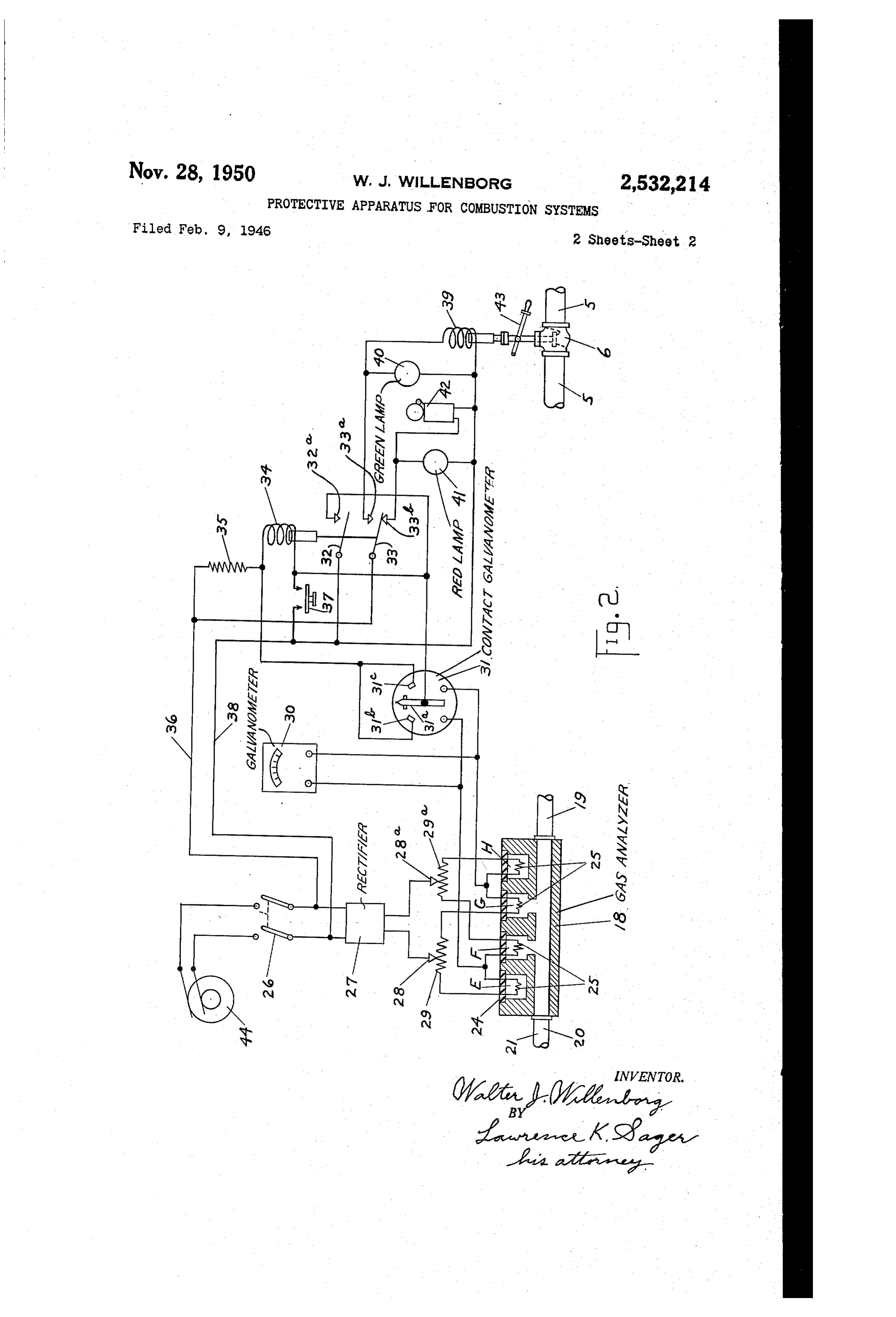
when water is added to cool the roasted material, the gas sample will continue to be supplied from The indicating and Control apparatus which the location B in the same path and the ana 25 is affected by the variable condition of the ana lyzer will respond to the condition of the exhaust lyzer or cell 8 is shown diagrammatically in gaSeS. Fig. 2 where the analyzer is shown at the lower In case the circulating fan 5 should stop, the left-hand portion. This is shown as a metal sample will be drawn 3rom both locations B and block having a through passage at its lower por D by the suction of the mixer fan at 8; and if 30 tion to the opposite ends of which are connected the fuel gas supply had not been fully shut off, the sampling pipes as shown in Fig. 1. In the any leak of gas would be picked up from either the upper portion of the block are cylindrical or both locations B and D and revealed by the cavities for the reception of cells of the character analyzer. described in the U. S. Patent No. 2,255,551 of If the circulating fan 5 should stop while the 35 W. J. Willenborg, granted September 9, 1941. burner 9 is active, the sample would be drawn There are four Such cells indicated inserted in from location D. The normal conditions would the cylindrical openings of the block 8 in Fig. 2 then lack the advantage of recirculation and the of the present case designated as E, F, G and H. fuel would burn rich and produce unburnt prod These cells are sealed against atmosphere by ucts which would affect the response of the ana 40 Sealing washers 24 and support electrical resis yzer. tors 25 preferably of platinum or tungsten, or If the mixer fan at 8 should stop while other other suitable metal, the resistance of which operating conditions continued, the positive varies with their change in temperature. The pressure due to the fan 5 would cause a flow of resistance of the resistors of the cells E and G sample gas from the location B through the cell is preferably made higher than that of the re f8 to locations A and C and also cause a portion sistors in cells F and H, this being determined of the gas to pass from B to D. The analyzer by their length, cross-section or their material. or cell 8 would, of course, then reveal too rich The openings in which the cells F and G are lo a mixture due to the unburnt gases. In Some cated are connected by the passages shown with cases the location B and the pipe therefrom may 5. the through passage in the metal block for the be omitted. In that case when the mixer fan purpose of Subjecting their resistors to the char stops, the negative pressure at location D will acter of the gases passing through the block; cause a flow of gas from locations A and C to but the resistors of the cells E and H being sealed and through the analyzer 8 from right to left remain subjected to the composition of the sealed and to location D. The analyzer Would then atmosphere.
respond to reveal too rich a mixture. Any changes in temperature of the analyzer or In shutting down for the idle condition, the block as a whole, due to change in ambient tem pilot gas valves f and 3 are closed as well as perature or to the temperature of the gases pass the main fuel Valve and then the mixer fan ing through the block will uniformly affect the and recirculating fan are stopped. Under this temperature of all the resistors and any result idle condition, the gas Sample passes through the O ing relative change in their resistance will not analyzer from right to left. This is due to the appreciably affect their response. minus pressure at B and D being greater than However, when the composition of the gases the minus pressure at C or A and thereby causing passing through the analyzer changes, the re sample gas to pass from locations A and C sistors in the cells; F and G will be aflected in through the analyzer from right to left. Any response to the thermal conductivity of the gases. eak through the pilot or main fuel Supply valves Thus if the gases, are of a composition having would then be revealed by the analyzer. Also if higher conductivity than normal safe conditions, either the pilot or main burner valves had been the resistance of the resistors in cells F and G left open when both fans were stopped, and o Will be reduced because their temperatures will whether or not the pilot and main burner con be lowered by the increased dissipation of heat tinued to burn, the analyzer would show this to the passing gases of higher thermal conduc undesirable condition, tivity, the resistors having a positive tempera It may be stated generally that the analyzer ture coefficient of resistance. This changes the or cell 8 will respond to any abnormal condi s resistance of the resistors in the cells F and G
Page 5
with reference to that of the unaffected resistors fixed contact 32d adapted to be engaged by the in the cells E and H. This relative change is contact 32 and also to the vane 3 a. and to one utilized for giving indications thereof and for side of a starting push button 3. The other side producing controlling effects when the change of the push button is connected to the supply line approaches a dangerous condition. It follows 38. The fixed contacts 3b and 3 for are both that any mixture of gases which has a higher Connected to the connection between the magnet thermal conductivity than that of the propernor Winding 34 and the resistor 5. The movable mal mixture may be detected by this means and contact 32 is connected to the supply line 8. continuously reveal the condition of the gases Another electromagnet having a winding 39 has under all operating and idle conditions. 0. one terminal of the winding connected to the It has been found that in combustion Systems Supply line 38 and its other terminal connected of the type to which this invention is applicable, to the fixed contact 33a adapted to be engaged by the unburnt gases have a higher thermal con the movable contact 33 when the winding 24 is ductivity than the most desirable mixture of the energized. The contact 33 is connected to the gases of combustion, such unburnt gases being Supply line 36. An indicating lamp 40 which for example the flammable gases such as hydro may have a green bulb is connected across the gen, methane and the like. These unburnt gases terminals of the magnet winding 39 showing may accumulate by having too rich or too lean When it is energized under normal operating a fuel mixture, or by raw fuel gas entering the conditions. An indicating lamp 4 which may system. Normally the oxygen content of the 20 have a red bulb and an alarm bell or other heated gases in the system is Small and the mix form of signal 42 are connected in parallel from ture is inert and prevents the ignition of flam the line 38 to the fixed contact 33b adapted to mable gases which may be present in the heated be engaged by the contact 33 when the magnet gases; but if this oxygen content be increased as winding 34 is deemergized. The valve 6 already by opening a door to the system or by any open 25 referred to in describing Fig. 1 as being in the ing permitting air to enter the interior, the re main fuel Supply pipe 5, is adapted to be held sulting explosive mixture might be dangerous in in its open position when the controlling wind the presence of a flame or spark, or a sufficiently ing 39 is energized and to be automatically closed high temperature. when the winding is deemergized. A pivoted hand In Fig. 2 the leads from the four resistors are lever 43 is provided for manually moving the carried out through the cells and are connected valve 6 to its open position where it is then held in a Wheatstone bridge arrangement. An alter provided the winding 39 be energized, nating current source 44 is adapted to be con Fig. 2 shows the parts in their complete shut nected by a switch 26 to a transformer and recti down condition. In starting up, the recirculat fier unit indicated at 27. The direct current leads ing fan 5 of the System should first be started therefrom are connected respectively to adjust to purge the System of any accumulated gases able contacts 28 and 28a, which engage variable and the mixer fan 8 should also be started. The resistors 29 and 29a for securing proper balancing switch 26 is then closed which supplies current of the circuits. One side of the bridge connection to the bridge circuit through the transformer and is from the contact 28 through a portion of the 40 rectifier 27. The pointer of the galvanometer 30 resistor 29, through the resistor in the cell E, then and the vane of the galvanometer 3 will then through the resistor in the cell F and thence Occupy their mid-positions, the contacts 28 and through a portion of the resistor 29a to the other 28a, having been adjusted for this condition. The side of the line at contact 28a. The other side push button 37 will then be closed temporarily of the bridge circuit is from the contact 28, which causes the winding 34 to be energized by a through a portion of the resistor 29, then through circuit from line 38 through the button, winding the resistor in the cell G, then the resistor in 34 and resistor 35 to line 36. This causes the the cell H and thence through a portion of re movable contacts 32 and 33 to engage their con sistor 29a to the contact 28a. A galvanometer tacts 32a and 33a. The winding 34 is then main 30 is connected across the bridge from a point tained energized by a circuit from line 38 through between E and F to a point between G and H. contacts 32, 32a, winding 34, resistor 35 to line 36. The galvanometer has a mid-scale Zero point and The engagement of the contacts 33 and 33a any change of resistance in the resistors of F closes a circuit through the winding 39 and the and G with reference to that of the resistors E green light 40 across the lines 36 and 38. The and H will cause a deflection of the indicating 5 5 control valve 6 may now be opened manually and needle to the right or left of the Zero point. The will be held open by the magnet if conditions scale plate may be divided into sections to indi remain normal. The pilot and runner valves cate normal operating conditions in the right and 3 of Fig. 1 when now opened permit the hand portion, and caution and danger conditions pilot and runner lights to be ignited. The fuel in the left-hand portion. An additional galvan 60 valve may now be opened which places the ometer 3 of the contacting type is connected in System in operation for starting the roast. parallel with the galvanometer 30 and similarly Under normal operating conditions, the needle responds to changes in the composition of the gases. The movable vane 31a, when sufficiently 85 and vane of the instruments 30 and 3 f move somewhat to the right of their mid-positions be deflected to the left engages a fixed contact 3b cause the heated gases then have a lower thermal and when deflected to the right engages the conductivity than the air previously in the sys fixed contact 3 ic. These fixed contacts may be tem as is determined by the sample gases passed adjustable toward and from the vane for de through the analyzer. The scale of the galva termining the critical conditions for the engage ment of the contacts by the vane. 70 nometer 30 maybe marked to indicate this normal A pair of movable contacts 32 and 33 are si desirable condition.
multaneously controlled by an electromagnet hav If the fuel gas mixture becomes leaner or ing a winding 34 connected from one terminal richer it will be indicated by movement of the through a resistor 35 to one side 36 of the Sup pointer from its normal position and the op ply line. The other terminal is connected to a 75 erator may then make adjustments of the fuel or
Page 6
air supply or both accordingly. These indica ing its circuit, the vane a will move fully to the tions of the galvanometer are, of course, due to right or left depending on which resistor is faulty. the change of resistance of the resistors in the This will short-circuit the winding 4 and cause cells F and G relatively to the resistance of the . the automatic closing of the valve 6, as already resistors in the cells E and H caused by the explained. The defective cell must then be re change in thermal conductivity of the Sample placed for restoring the normal functioning of gases. The result is to modify the relative drop the control.
in volts in the resistors of the bridge circuit, giv Although a particular embodiment of the in ing a corresponding indication by the galvanonvention has been shown and described as applied eter in the usual function of a Wheatstone O to one form of combustion apparatus using illu bridge. minating gas as the fuel in a roaster, it will be In case the presence of flammable gases be understood that the invention is applicable to comes unduly high due to any of the causes al other combustion systems and to the use of other ready referred to, such as an extinguished pilot fuels. In Some cases where the character of the light, the needle will swing to the left of the mid s apparatus does not produce sufficient difference scale position into a region which may be marked in pressures to pass the sample gases through the caution. This gives a warning to the operator analyzer under the various conditions which may to correct the trouble. However, if the cond arise, Special means may be added to the appa tion be not...remedied and the accumulation of ratus for producing the pressure differences. Also flammable gases be allowed to continue Sufi 20 Various modifications of the invention may be made for adaptation to particular requirements ciently, the needle will move further to the left without departing from the scope of the claims. to a region which may be marked danger. The I claira:
vane 3a of the other galvanometer has the same movement as the needle, moving to the left as a 1. The combination of combustion apparatus having a gaseous fuel Supply including a supply dangerous condition is approached. The fixed 25 pipe, contact 3b is so positioned that it will be en conduit means for withdrawing gases from Said apparatus, an analyzer in Said conduit means gaged by the vane 3a at a condition well below having a resistor responsive to the amount of the attaining of a condition when an explosion flammable gases present in the composition of the might result, giving an ample factor of Safety. 3) gases
Such contact engagement will short-circuit the withdrawn from the apparatus by the magnet winding 34 by a circuit from the upper change of its resistance upon the lowering of its terminal of the winding through 3fb and 3 a to temperature by the presence of such flammable the lower terminal of the winding. This magnet gases, a bridge circuit wherein Said resistor is is then deenergized causing an opening at con connected in one of the legs of the bridge circuit, tacts 32a and 33a and a closing at contact 33b. ' a shut-off valve in the supply pipe of the fuel The holding circuit of the winding 34 is there Supply, a contact device electrically connected to by opened as well as the circuit of winding 39. said bridge circuit and actuated to its closed posi The control valve 6 is then automatically closed tion when the presence of the flammable gases in shutting off all fuel supply. The operator must said apparatus approaches a dangerous condition, and electromagnetic means affected by the closing then close the fuel valve 7 and pilot valves of Said contact device for closing Said Valve. and 3, purge the System and restart in the 2. The combination of combustion apparatus manner described after remedying the trouble. having a gaseous fuel Supply including a Supply When the winding 39 is automatically deener pipe, a burner and a pilot light, an analyzer hav gized, the contact 33 engages the contact 33b ing a resistor responsive to the amount of flam which closes the alarm and red light circuit mable gases passed through the analyzer by the across the supply lines giving a signal to the change of its resistance upon the lowering of its operator of the automatic shut-off. It will be temperature by the presence of Such flammable understood that under any of the abnormal con gases, a pipe connection for Supplying said ana ditions previously described arising during Op lyzer with a gas sample from the region near but eration, the analyzer will respond to affect the Spaced from the pilot light, a bridge circuit bridge circuit, the instruments and the auto wherein said resistor is connected in one of the matic control apparatus according to the con legs of the bridge circuit, a shut-off valve in the position of the gases in the different parts of the Supply pipe of the fuel supply, a contact device System. electrically connected to said bridge circuit and Also when the system is idle, as between roasts actuated to its closed position when the presence or over longer periods, and the magnet windings of the flammable gases in Said analyzer ap 34 and 39 remain energized, which is the normal proaches a dangerous condition, and electronag non-operating condition, the analyzer will re netic means affected by the closing of said con veal the condition of the gases to the instruments 00 tact device for closing said valve. and cause the controls to function in the manner 3. The combination of combustion apparatus just described, it having been explained in con having a gaseous fuel supply including a supply nection with Fig. 1 how the sample gases are pipe and a recirculating system of the burnt gases, passed through the analyzer during idle condi an analyzer having a resistor responsive to the tions as well as during operating conditions. amount of flammable gases present in the compo Thus any of the abnormal conditions which may sition of the gases passed through the analyzer occur, such as the various examples already ex by the change of its resistance upon the lowering plained, will be revealed by the control apparatus of its temperature by the presence of such flam and result in its automatic action if a dangerous nable gases, a pipe connection from a portion of condition is sufficiently approached. the recirculating system for supplying a gas A further protection is secured by the automatic Sample therefrom to the analyzer, a bridge cir control of the valve 6 in case of failure of any of cuit Wherein said resistor is connected in one of the resistors in any one of the cells. The contact the legs of the bridge circuit, a shutoff valve in c of the instrument 3 is connected With the the Supply pipe of the fuel supply, a contact de contact b, If any One resistor falls, as by Open 75 vice electrically connected to said bridge circuit
Page 7
and actuated to its closed position when the pres the analyzer to the region near but spaced from ence of the flammable gases passed through the the pilot light, a pipe connection from the other analyzer from a portion of the recirculating sys side of the analyzer to a region in the path of tem approaches a dangerous condition, and elec the burnt gases, a bridge circuit wherein said tromagnetic means affected by the closing of said 5 resistor is connected in one of the legs of the contact device for closing said valve. bridge circuit, a shut-off valve in the Supply pipe 4. The combination of combustion apparatus of the fuel Supply to the apparatus, a contact having a gaseous fuel supply including a supply device electrically connected to said bridge cir pipe, a fuel burner, an analyzer having a resistor cuit and actuated to its closed position when the responsive to the amount of flammable gases O presence of the flammable gases passes through passed through the analyzer by the change of its said analyzer approaches a dangerous condition, resistance upon the lowering of its temperature by and electromagnetic means affected by the clos the presence of such flammable gases, a pipe con ing of Said contact device for closing Said valve. nection from said apparatus in the region of the 7. The combination of combustion apparatus burnt gases for Supplying a gas. Sample there 15 having a gaseous fuel Supply including a Supply from to the analyzer, a bridge circuit wherein pipe, conduit means for withdrawing gases from said resistor is connected in one of the legs of said apparatus, an analyzer in Said conduit means the bridge circuit, a shut-off valve in the Supply having a resistor responsive to the amount of pipe of the fuel Supply, a contact device elec flammable gases present in the composition of trically connected to Said bridge circuit and ac 20 the gases withdrawn from the apparatus by the tuated to its closed position when the presence change of its resistance upon the lowering of its of the flammable gases in Said burnt gases ap temperature by the presence of Such flammable proaches a dangerous condition, and electronag gases, a bridge circuit wherein said resistor is netic means affected by the closing of said con connected in one of the legs of the bridge circuit, tact device for closing Said valve. a shut-off valve in the supply pipe of the fuel 5. The combination of combustion apparatus Supply, a signal, a contact device electrically having a gaseous fuel burner and a fuel supply connected to said bridge circuit and actuated to pipe therefor, a power driven mixer for Supply its closed position when the presence of the ing combustible gases to the apparatus, an an flammable gases in said apparatus approaches alyzer having a resistor responsive to the amount of flammable gases present in the composition ameans dangerous condition, and electromagnetic affected by the closing of said contact of the gases passed through the analyzer by the device for closing said valve and for Operating change of its resistance upon the lowering of its said signal.
temperature by the presence of such flammable WALTER, J. WILLENBORG. gases, a pipe connection from One side of the 35 analyzer to the suction intake of Said mixer, a REFERENCES (CTED pipe connection from the other side of the an The following references are of record in the alyzer to a region in the path of the gases, a file of this patent:
bridge circuit wherein said resistor is connected in one of the legs of the bridge circuit, a shut 40 UNITED STATES PATENTS of valve in the supply pipe of the fuel supply, a Number Name Date contact device electrically connected to said 899,068 Philip et al.-------- Sept. 22, 1908 bridge circuit and actuated to its closed position 1770,059 Barber ------------- July 8, 1930 when the presence of the flammable gases passed 1809,280 Knowles. ----------- June 9, 1931 through the analyzer approaches a dangerous 1900,884 Lusby -------------- Mar. 7, 1933 condition, and electromagnetic means affected 1953,244 Luckey et al. -------- Apr. 3, 1934 by the closing of said contact device for closing 2,116,239 Hebler ------------- May 3, 1938 said valve.
6. The combination of combustion apparatus 50 2,142,059
having a gaseous fuel burner and a fuel supply 2,231,166 Knoedler, Jr. ------ Feb. 11, 1941 pipe therefor, a pilot light for the burner, an 2,237,558 Hutton ------------- Apr. 8, 1941 analyzer having a resistor responsive to the 2,324,821 Campbell ---------- July 20, 1943 amount of flammable gases present in the com 2,341,727 Krogh ------------- Feb. 5, 1944 position of the gases passed through the analyzer 2,352,143 Wills -------------- June 20, 1944 by the change of its resistance upon the lowering 2,361,294 Jones -------------- Oct. 24, 1944 of its temperature by the presence of such flam 2,441,677 Stallsmith --------- May 18, 1948 mable gases, a pipe connection from one side of
Provenance
- Collection
- Cited prior art
- Original PDF
- patentimages.storage.googleapis.com →
- Filed
- 1946-02-09
- Pages
- 7
- Method
- pdftotext (the PDF's own text layer) + pdftoppm 300dpi page scans
- Source
- Google Patents bibliographic record
- Granted
- 1950-11-28
- Inventors
- Walter J Willenborg; Jabez Burns and Sons Inc
- Transcribed from
- patentimages.storage.googleapis.com →