patent · US20020129798A1
System and method for auto-ignition support
19 September 2002
Page 1 — bibliographic record
(19) United States (12) Patent Application Publication (10) Pub. No.: US 2002/0129798A1
Urushihara et al. (43) Pub. Date: Sep. 19, 2002 (54) SYSTEM AND METHOD FOR (30) Foreign Application Priority Data
AUTO-IGNITION SUPPORT
Mar. 13, 2001 (JP)...................................... 2001-0702O1 (75) Inventors: Tomonori Urushihara, Yokohama (JP); Publication Classification Koichi Yamaguchi, Yokohama (JP);
Kazuya Hasegawa, Tokyo (JP); (51) Int. Cl." .................................................... F02M 25/07 Koudai Yoshizawa, Kanagawa (JP) (52) U.S. Cl. ........................................................ 123/568.13 Correspondence Address: (57) ABSTRACT
FOLEY AND LARDNER
SUTE 500 An internal combustion engine includes a cylinder including 3000 KSTREET NW at least one intake valve which is Selectively open to allow WASHINGTON, DC 20007 (US) at least air to enter the cylinder and at least one exhaust valve which is Selectively open to allow residual gas escape from (73) Assignee: NISSAN MOTOR CO.,LTD. the cylinder after a firing event. An auto-ignition System for Such an engine comprises a device communicably coupled (21) Appl. No.: 10/094,970 with the cylinder. The device is, effective to allow an amount of high temperature and pressure residual gas to enter the cylinder in the compression Stroke of an engine cycle after (22) Filed: Mar. 12, 2002 valve closure of the intake valve.
- ACCEL. PEDAL POSITON ENGINE CONTROL UNIT ENGINE SPEED
SUPPORT
CONTROLLER
Y - PHASE
RoM KAM
Page 2
Drawing sheet — no readable text.
Page 3
Drawing sheet — no readable text.
Page 4
Drawing sheet — no readable text.
Page 5
Drawing sheet — no readable text.
Page 6
Drawing sheet — no readable text.
Page 7
Drawing sheet — no readable text.
Page 8
Drawing sheet — no readable text.
Page 9
Drawing sheet — no readable text.
Page 10
Patent Application Publication Sep.19, 2002 Sheet 9 of 10 US 2002/0129798 A1
TRAP VALVE TRAP WALVE
TDC
DELAYED TRAP
WALWE TIMING
EARLY TRAP
WALWE TIMING
SPARK-IGNITION COMBUSTION REGION
LOAD (TRAP WALVE INACTIVATED)
AUTO-IGNITION COMBUSTION REGION
(TRAP VALVE ACTIVATED)
TRAP WAVE TIMING ADVANCING
ENGINE SPEED
Page 11
Patent Application Publication Sep.19, 2002 Sheet 10 of 10 US 2002/0129798 A1
FOR ONE ENGINE CYCLE, ALLOW
ESCAPE OF A PORTION OFRESIDUAL
FIRNG EVENT BEFORE THE CYLNDER
EXHAUST WALVES OPEN
TRAP THE PORTION OF RESIDUAL GAS O4
ESCAPED FROM THE CYLNDER
FOR THE SUBSEGUENT CYCLE ALLOW
THE TRAPPEDPORTION OFRESIDUAL
GAS TO ENTER THE CYLNDER IN THE 106
COMPRESSION STROKE OF THE
ENGINE CYCLE AFTER CLOSURE OF
THE CYLNDER INTAKE WALVE
Page 12
US 2002/0129798 A1 Sep. 19, 2002
SYSTEMAND METHOD FOR AUTO-IGNITION 0012 said valve actuator being effective to selec SUPPORT tively open Said trap valve to allow escape of a portion of residual gas from the cylinder to Said trap
BACKGROUND OF THE INVENTION chamber in the power Stroke of one engine cycle before valve opening angle of the exhaust valve and 0001) 1. Field of the Invention to trap said portion of residual gas escaped from the 0002 The present invention relates to an auto-ignition cylinder,
Support System and method for internal combustion engines 0013 said valve actuator being further effective to including heterogeneous-charge, compression-ignition four Selectively open Said trap valve to allow Said trapped cycle engines and homogeneous-charge compression-igni portion of residual gas to enter the cylinder in the tion four-cycle engines. compression Stroke of the Subsequent engine cycle 0.003 2. Description of the Background Art after valve closure of the intake valve.
0004. It is known practice to design four-stroke cycle 0014. According to still another aspect of the present internal combustion engines to accommodate auto-ignition invention, there is provided an auto-ignition Support method (or compression-ignition) combustion. It is proposed to for an internal combustion engine including a cylinder control auto-ignition timing by changing the temperature of including at least one intake valve which is Selectively open fresh charge of air and fuel mixture by heating the intake air. to allow at least air to enter the cylinder and at least one It is also proposed by JP-A 11-343874 to use heat energy of exhaust valve which is Selectively open to allow residual gas a portion of residual gas escaped from cylinder in the power escape from the cylinder after a firing event, the method Stroke of one engine cycle to heat fresh charge of the comprising:
Subsequent engine cycle. 0.015 for one engine
y allowing9. escape
0005 Although it is possible to control auto-ignition portion of residual gas from the cylinder during the timing by heating fresh charge using the heat energy of power Stroke before the exhaust valve is open; residual gas of the preceding engine cycle, a need remains 0016 trapping said portion of residual gas escaped for improvement of System and method for auto-ignition from the cylinder; and
Support for practical application to internal combustion engines. 0017 for the subsequent engine cycle, allowing said trapped portion of residual gas to enter the cylinder
SUMMARY OF THE INVENTION in the compression Stroke after valve closure of the intake valve.
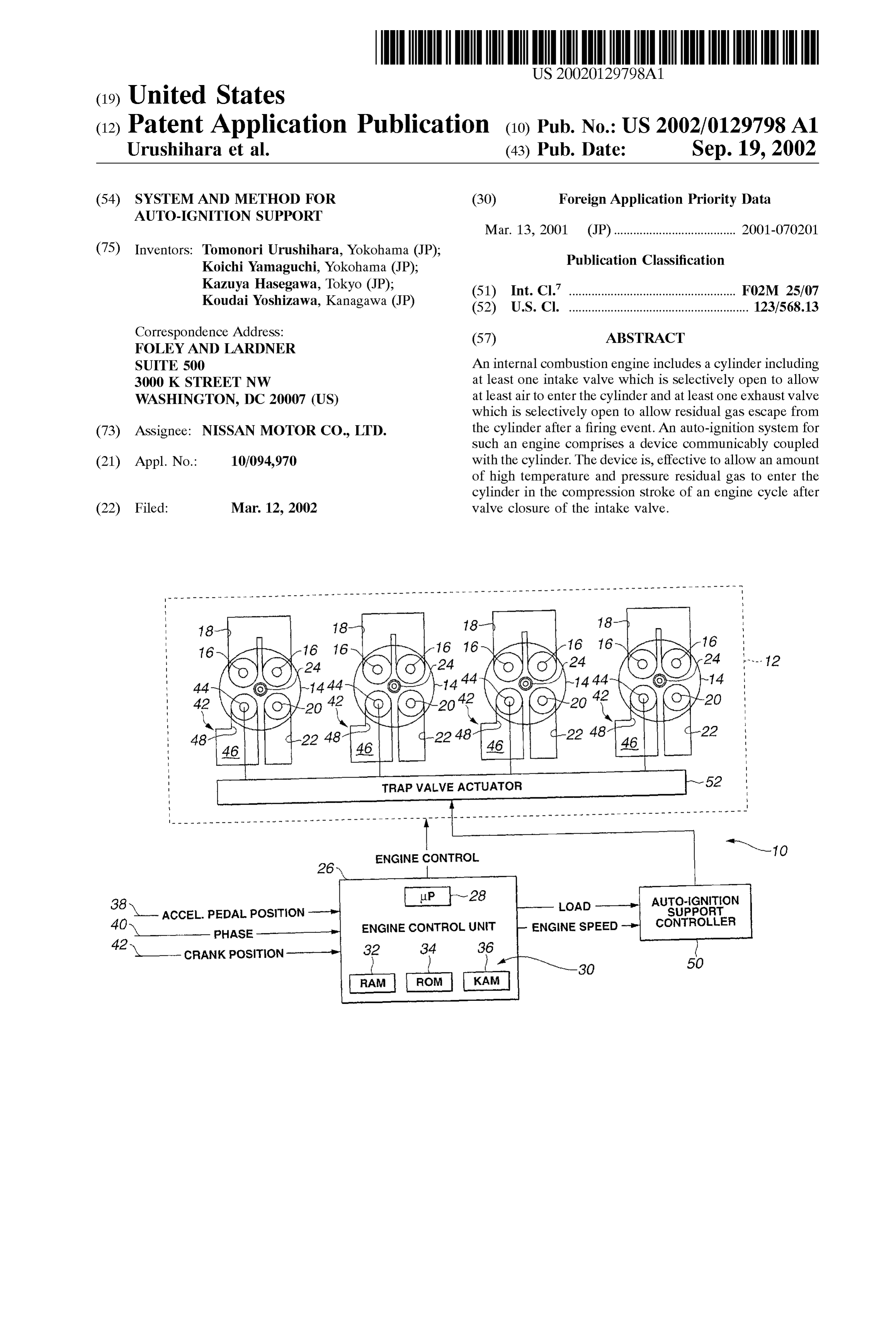
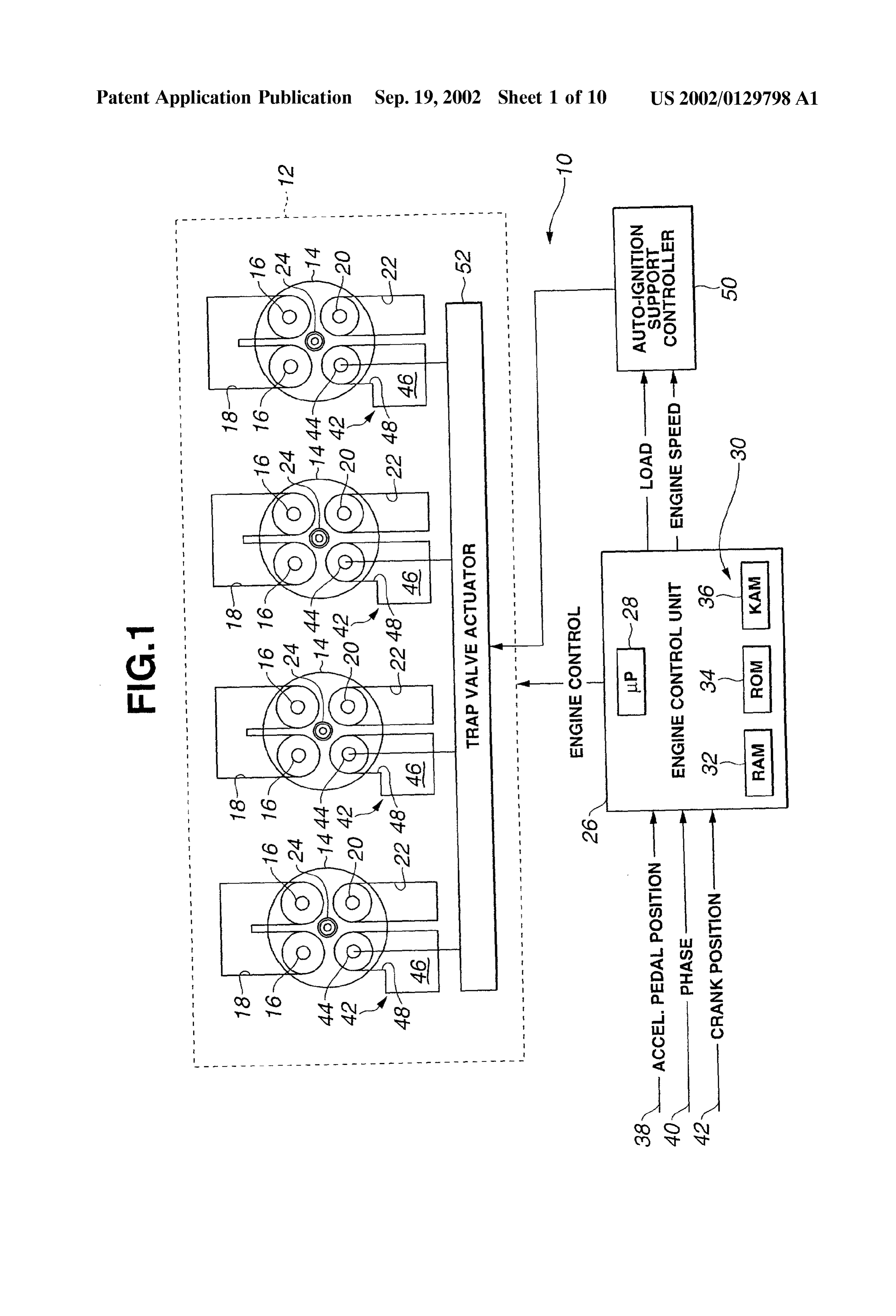
0006 An object of the present invention is to provide auto-ignition Support System and method for four-stroke BRIEF DESCRIPTION OF THE DRAWINGS cycle internal combustion engines to meet the above-men tioned need. 0018 Further objects and advantages of the invention 0007 According to one aspect of the present invention, will be apparent from reading of the following description in there is provided an auto-ignition Support System for an conjunction with the accompanying drawings. internal combustion engine including a cylinder including at 0019 FIG. 1 is block diagram of an exemplary embodi least one intake Valve which is Selectively open to allow at ment.
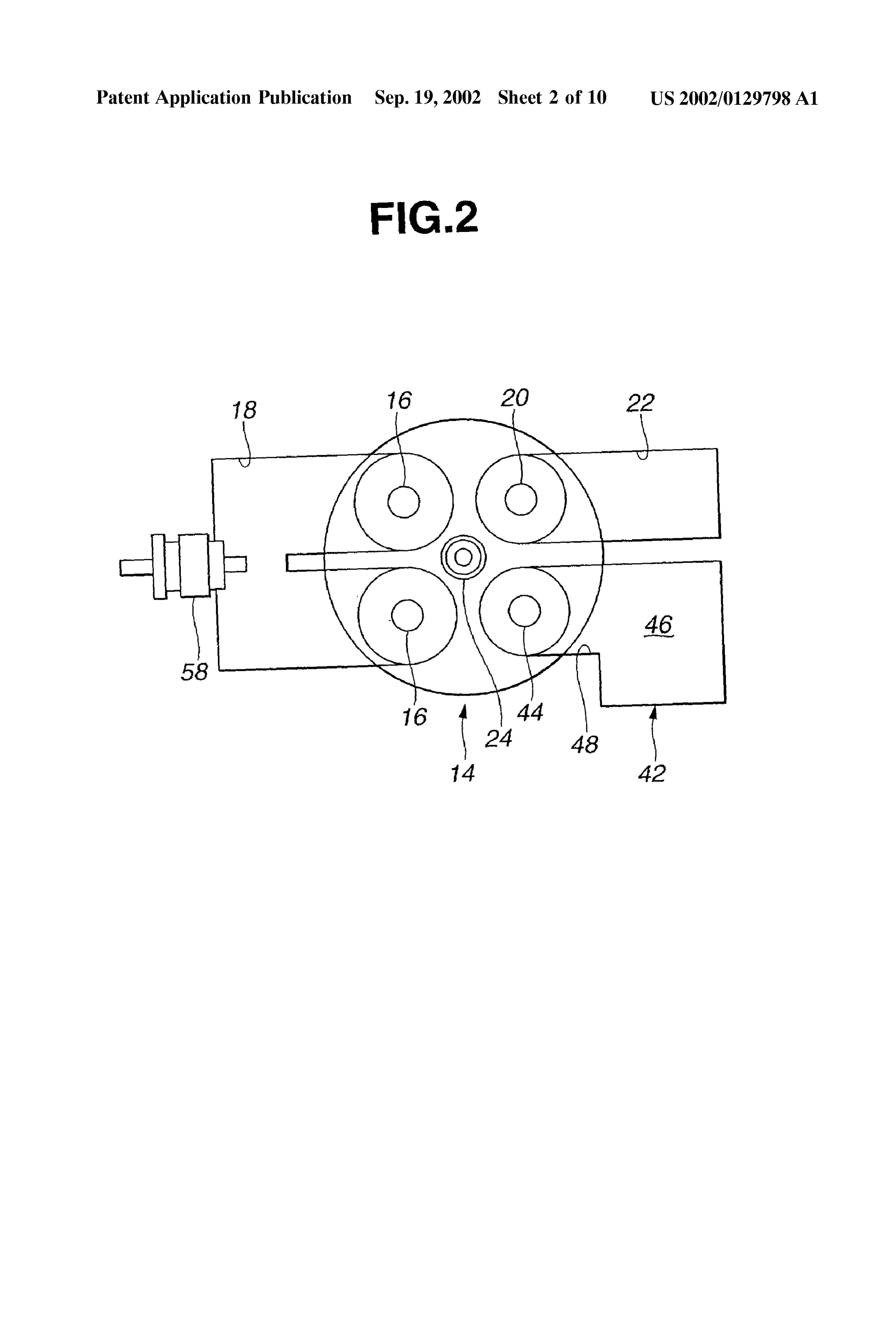
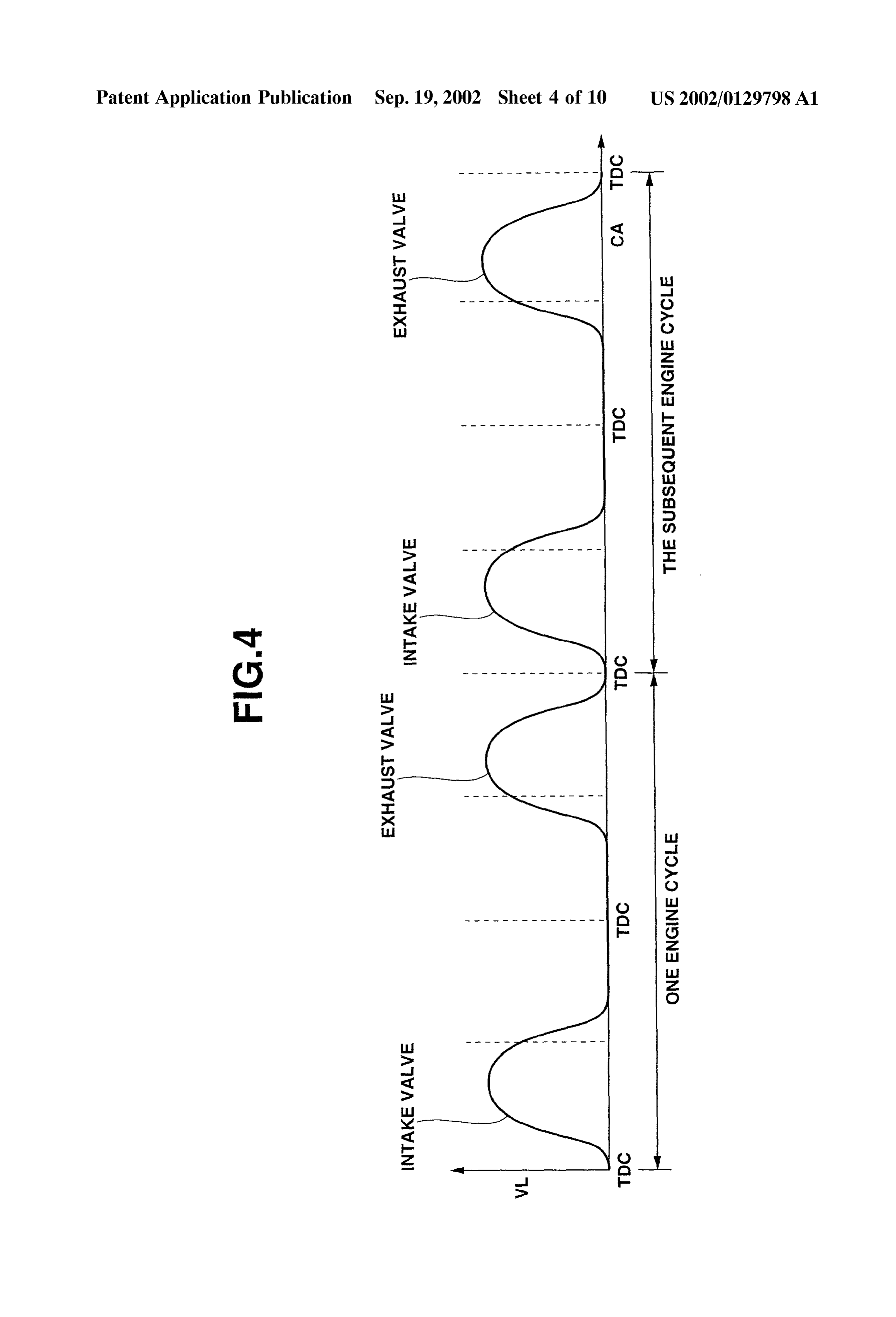
least air to enter the cylinder and at least one exhaust valve 0020 FIG. 2 is a fragmentary view of FIG. 1. which is Selectively open to allow residual gas escape from the cylinder after a firing event, the System comprising: 0021 FIG. 3 is a valve lift diagram of an intake valve, an 0008 a device communicably coupled with the cyl exhaust valve and a trap valve over one engine cycle and the Subsequent engine cycle when the engine is operable in an inder, effective to allow an amount of gas to enter the auto-ignition combustion operating region of a load and cylinder in the compression Stroke of an engine cycle engine Speed relationship.
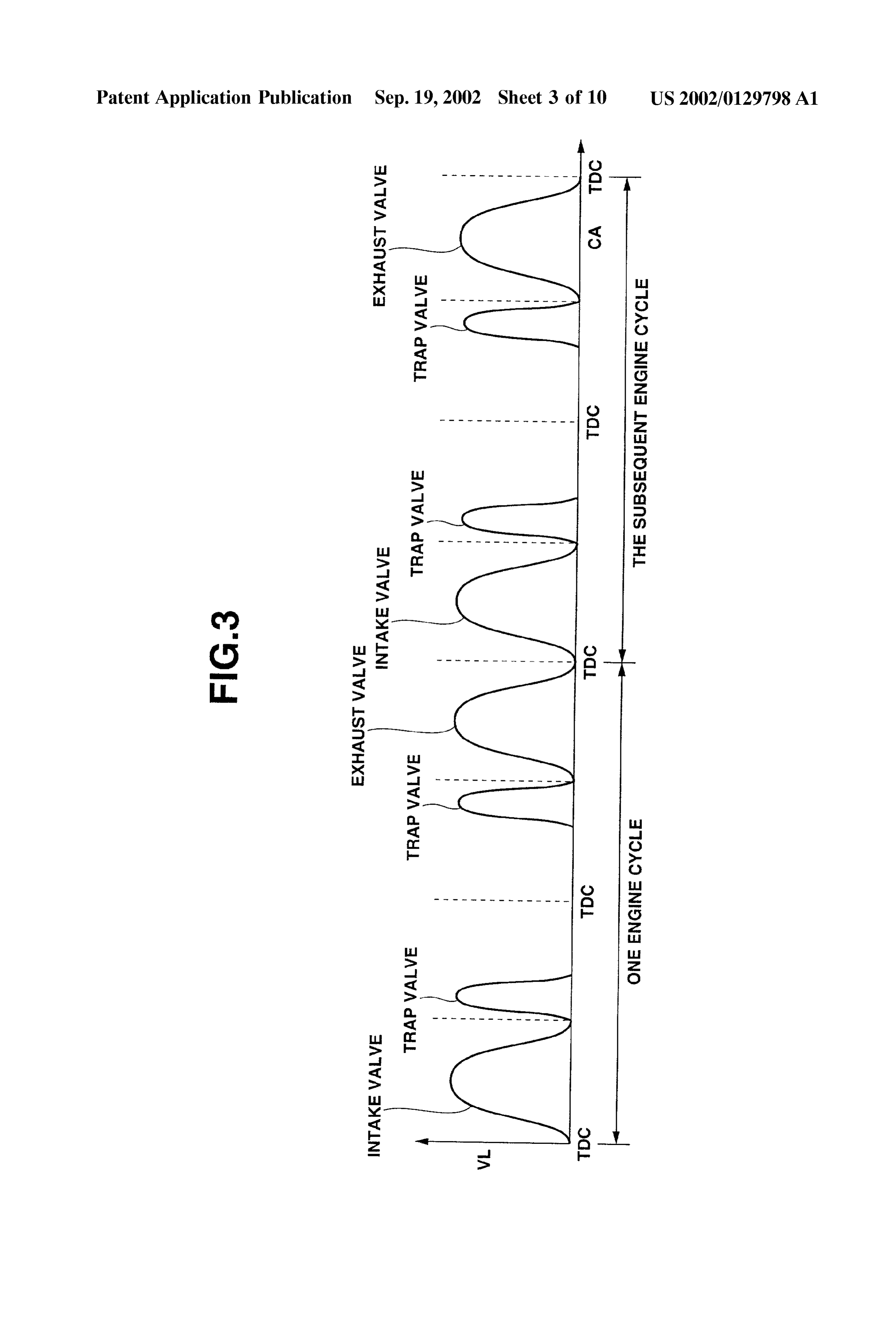
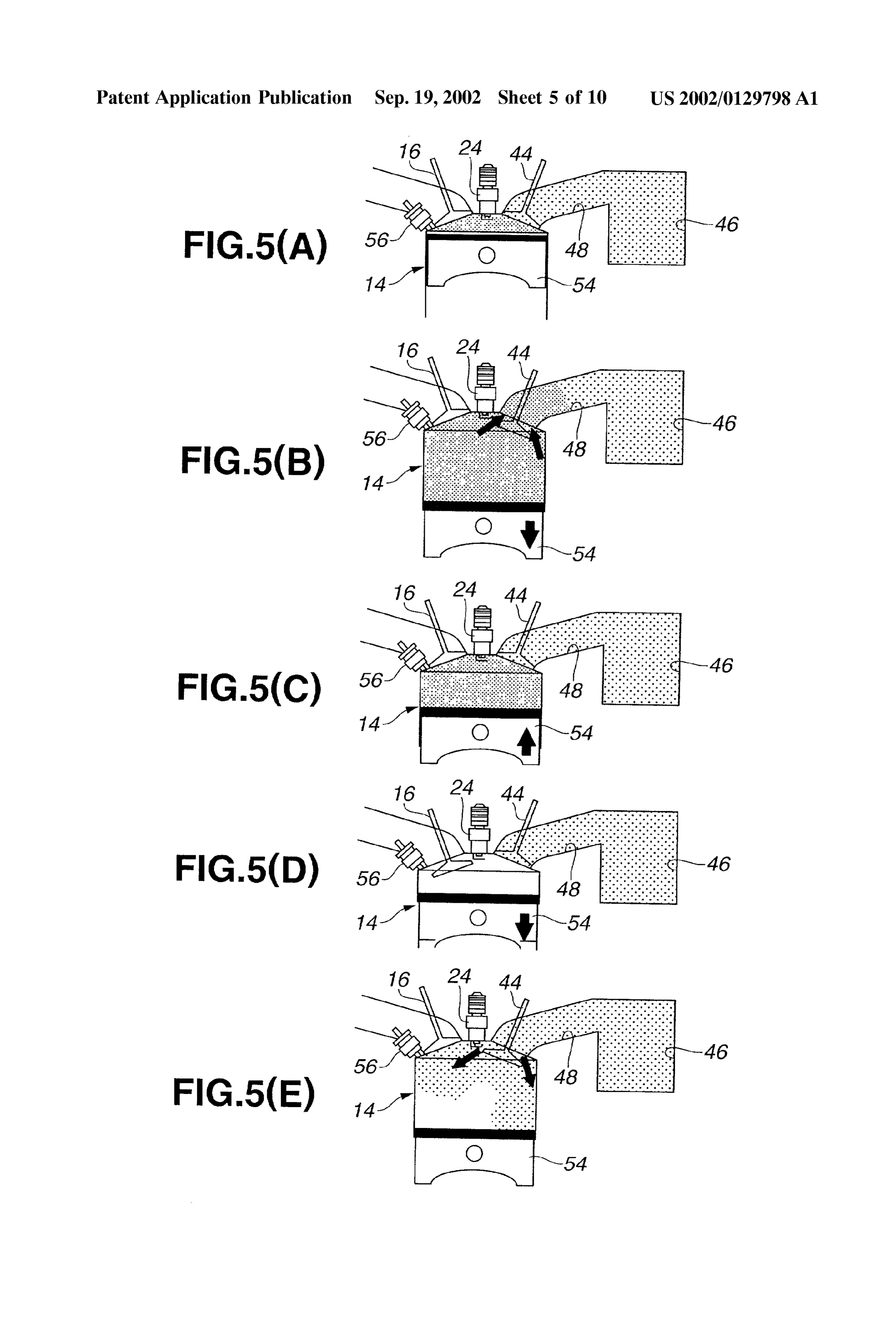
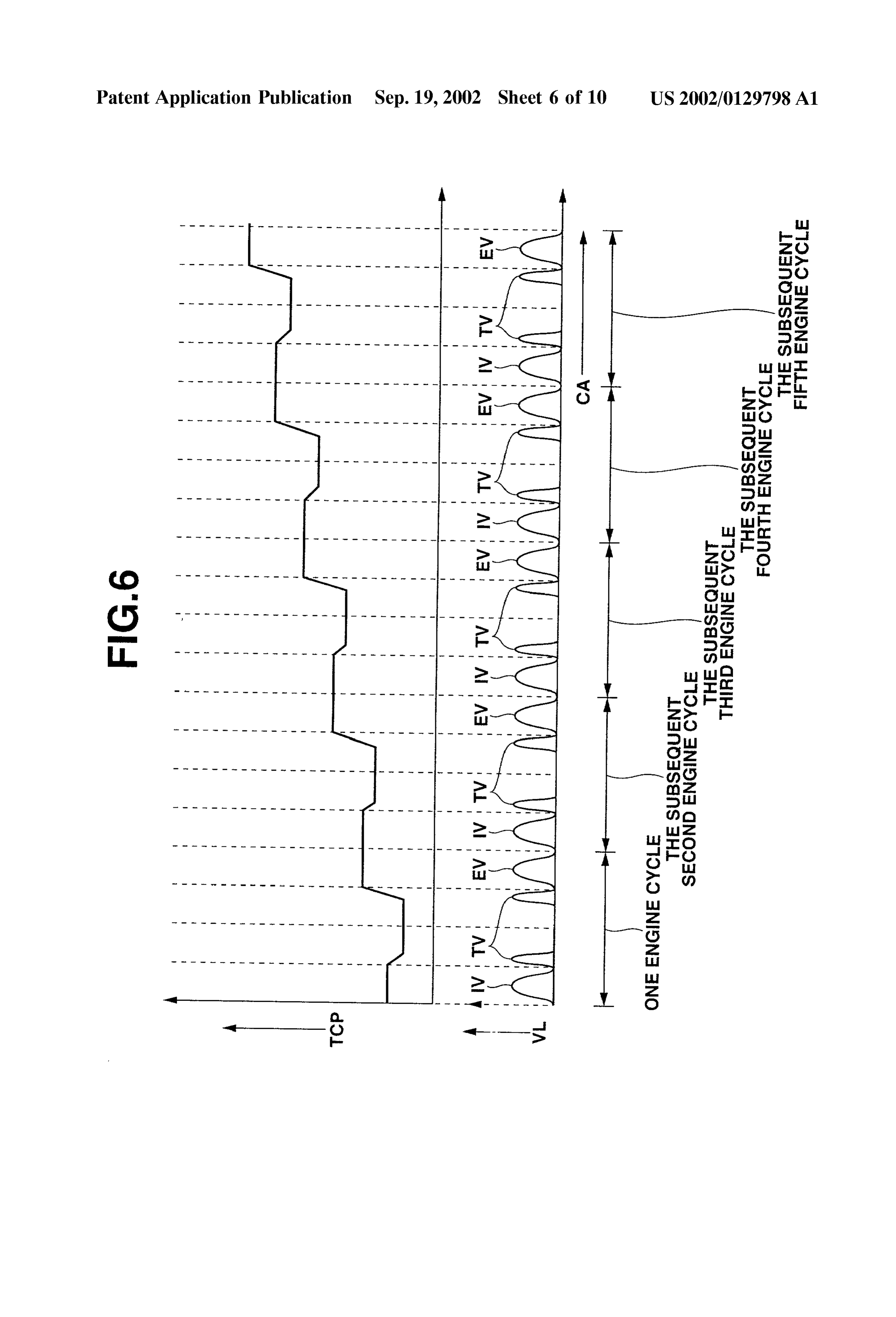
after valve closure of the intake valve, Said gas being higher in temperature than the air that is allowed to 0022 FIG. 4 is a valve lift diagram over one engine cycle enter the cylinder when the intake valve is open. and the Subsequent engine cycle of the one cylinder when the engine is operable in a Spark-ignition combustion region 0009. According to another aspect of the present inven of a load and engine Speed relationship. tion, there is provided an auto-ignition Support System for an internal combustion engine including a cylinder including at 0023 FIGS. 5(A) to 5(E) are pictorial views illustrating least one intake Valve which is Selectively open to allow at five phases beginning with the power Stroke of one engine least air to enter the cylinder and at least one exhaust valve cycle and ending with early part of the compression Stroke which is Selectively open to allow residual gas escape from of the Subsequent engine cycle when the engine is operable the cylinder after a firing event, the System comprising: in auto-ignition combustion operating region. 0010 a gas trap including a trap valve, and a trap 0024 FIG. 6 shows the relationship between crank angle chamber selectively communicable with the cylinder (CA) and trap chamber pressure (TCP) for six engine cycles through a port when said trap valve is open; and together with a valve lift diagram immediately after initia tion of engine operation in auto-ignition combustion oper 0011 a valve actuator which selectively actuates ating region of a given fixed load and engine Speed rela Said trap valve, tionship.
Page 13
US 2002/0129798 A1 Sep. 19, 2002
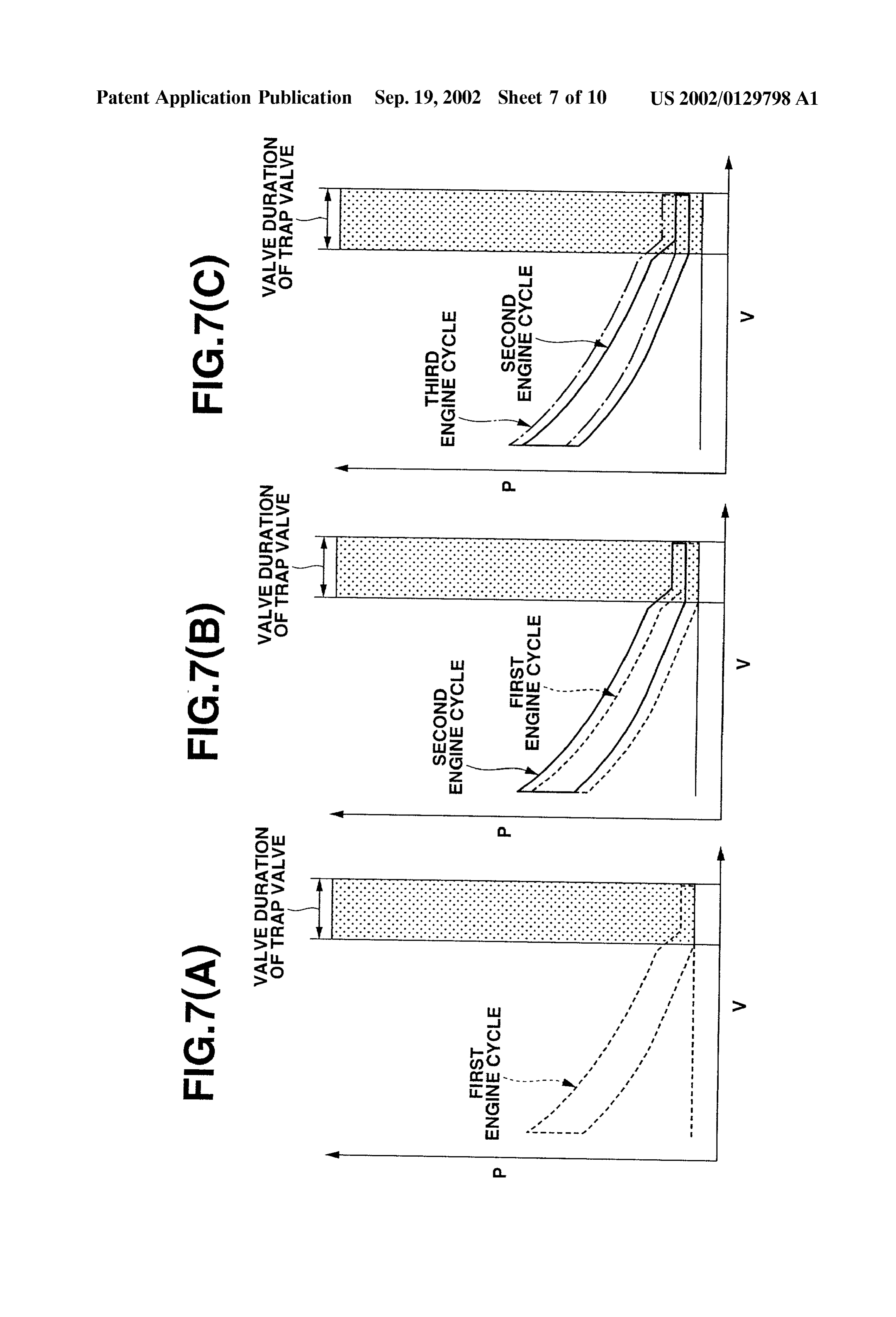
0025 FIGS. 7(A) to 7(C) are P-V diagrams within trap a read-only memory (ROM)34, and/or a keep-alive memory chamber for three engine cycles immediately after initiation (KAM) 36. These functions may be carried out through any of engine operation in auto-ignition combustion operating one of a number of known physical devices including region of the fixed load and engine Speed relationship. EPROM, EEPROM, flash memory, and the like. Engine 0026 FIG. 8(A) shows the relationship between CA and control unit 26 also includes appropriate electronic circuitry, cylinder charge mass (mol), graphically illustrating the trend integrated circuits, and the like to carry out control of the of cylinder content for a number of engine cycles after engine. AS Such, engine control unit 26 is used to carry out initiation of auto-ignition combustion mode when trap valve control logic implemented in terms of Software (instruc is open over the last portion of induction Stroke and the tions) and or hardware components. Details of control logic initial portion of the Subsequent compression Stroke. implemented by engine control unit 26 are readily derivable as the discussion proceeds.
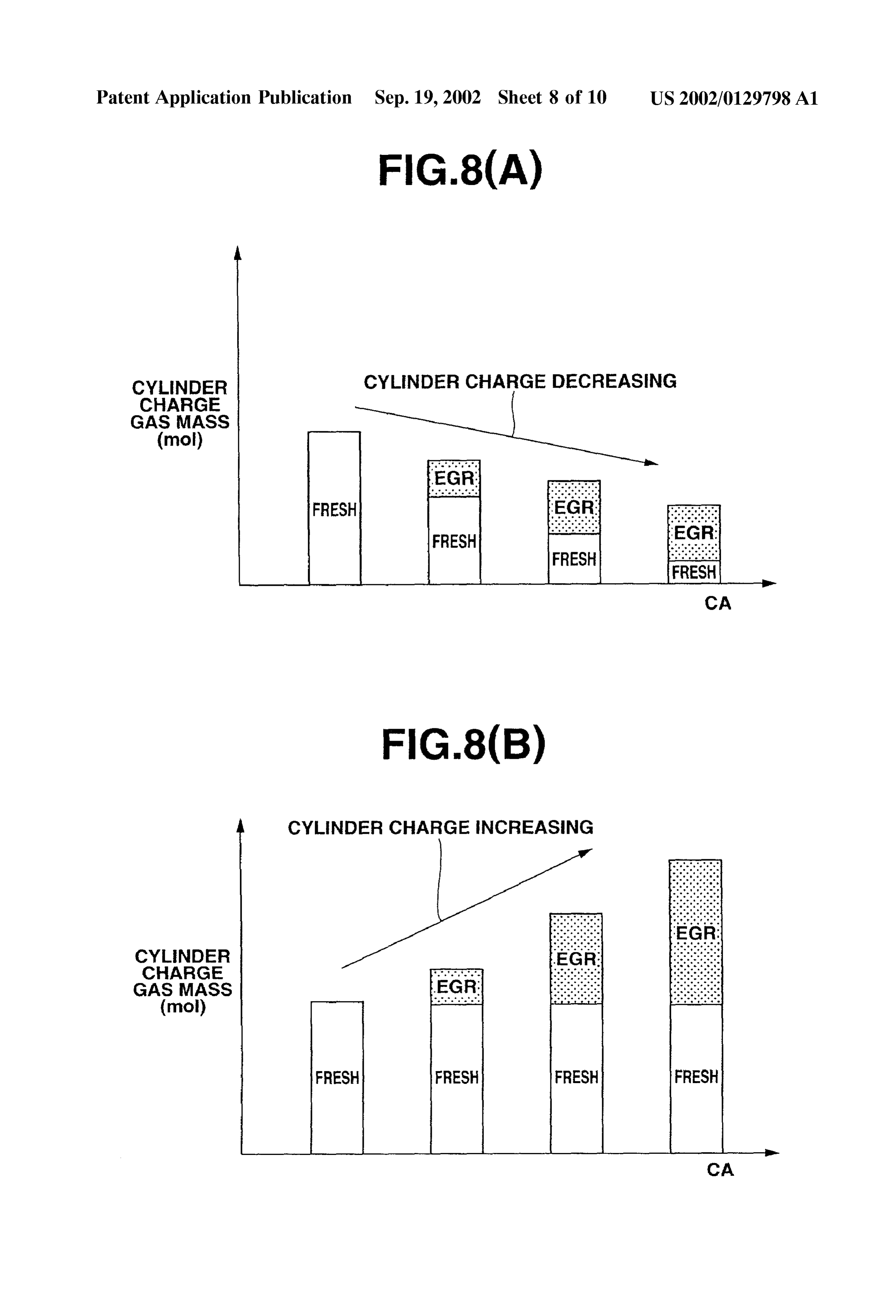
0027 FIG. 8(B) shows the relationship between CA and 0033 Engine control unit 26 receives various signals cylinder charge mass, graphically illustrating the trend of cylinder content for the same number of engine cycles after from Sensors, Switches, and other input devices to monitor initiation of auto-ignition combustion mode when trap valve current operating conditions of the vehicle. For example, is open in the compression Stroke after the valve closure of Signals may include an accelerator pedal position Signal 38, intake valve. a phase signal 40, and a crank position Signal 42. AS will be appreciable by one of ordinary skill in the art, engine control 0028 FIG. 9 is a valve lift diagram of one engine cycle, unit 26 determines load and engine Speed based on Some of illustrating an early trap valve timing and a delayed trap Such signals.
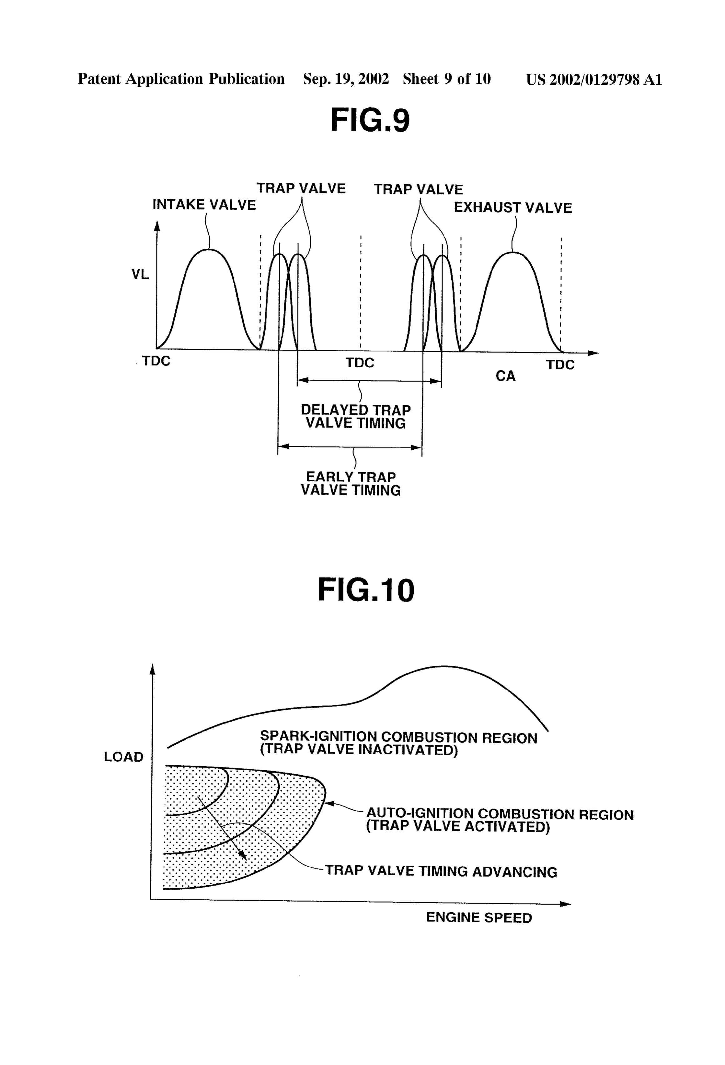
Valve timing between which the trap valve timing moves to 0034. As will be appreciated as the discussion proceeds, advance or retard the valve opening when the engine is auto-ignition Support System 10 includes a device commu operable in auto-ignition combustion operating region of nicably coupled with each cylinder 14, effective to allow an different load and engine Speed relationships. amount of gas to enter the cylinder in the compression Stroke 0029 FIG. 10 is a load-speed characteristic for the of each engine cycle after valve closure of the associated engine, wherein an area filled with dots indicates the auto intake valve 16. The gas is higher in temperature than the ignition combustion operating region. intake air that is allowed to enter cylinder 14 when intake 0030 FIG. 11 is a flow diagram illustrating an auto valve 16 is open.
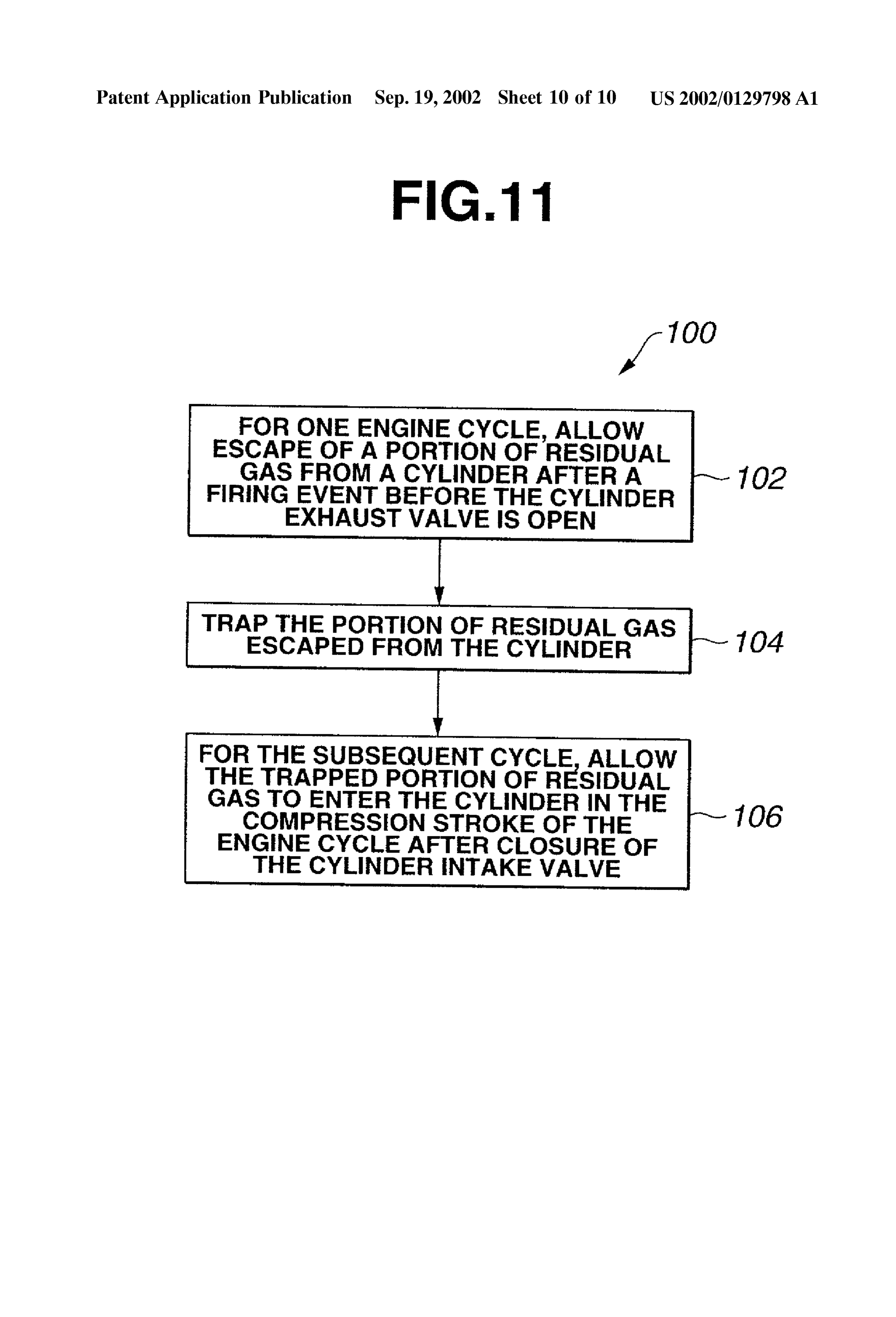
ignition Support method of the present invention. 0035) In one exemplary embodiment of the present invention, system 10 includes several Substantially identical
DETAILED DESCRIPTION OF THE gas traps 42. Each gas trap 42 includes a trap valve 44, and INVENTION a trap chamber 46 selectively communicable with one of cylinders 14 through a communication port 48 when trap 0031 Referring to FIGS. 1 and 2, there is shown an valve 44 is open. While four gas traps 42 are illustrated in auto-ignition Support System 10 which is made and utilized FIG. 1, communicably coupled with four cylinders 14, in accordance with the teachings of the exemplary embodi respectively, the present auto-ignition Support System 10 ment of the present invention in order to ensure auto-ignition may use a gas trap including trap valves for the respective in each of cylinders of an engine. Particularly, System 10 is cylinders, and a common rail trap chamber Selectively adapted for use in auto-ignition within an internal combus communicable with Selected one of the cylinders through tion engine 12 including Several Substantially identical cyl one of communication ports when the associated trap valve inders 14. Each cylinder 14 includes at least one intake valve is open.
16, which is selectively open to allow at least air to enter the cylinder through intake port 18, a fuel injector, not illus 0036). In the embodiment, system 10 also includes an trated, positioned to inject fuel directly into the cylinder, at auto-ignition Support controller 50, and, for each cylinder least one exhaust valve 20, which is selectively open to 14, a valve actuator illustrated by a block 52 in FIG. 1, allow residual or exhaust gas escape from the cylinder which Selectively actuates the associated one trap valve 44. through exhaust port after a firing event of air and fuel In the embodiment, controller 50 comprises a portion of mixture, a Spark plug 24, and a conventional piston, not engine control unit 26. In one alternate embodiment, con illustrated, slidably disposed within cylinder 14. While, a troller 50 is a conventional controller including one or more four-stroke cycle internal combustion engine having four microprocessors. In other alternate embodiments, controller cylinders is illustrated in FIG. 1, it should be appreciated 50 is externally coupled to engine control unit 26. Controller that the present system 10 may be used in combination with 50 is communicably coupled to trap valve actuator 52, other types of engines having different numbers of cylinders effective to Selectively communicate a control Signal to and/or valves. Valve actuator 52. AS discussed more fully and completely 0.032 Engine 12 further includes a conventional engine below, controller 50 includes one or more valve timing control unit 26, which includes a microprocessor-based Strategies, which it uses to control the timing of the trap valves 44.
controller generally represented by reference numeral 28.
The microprocessor 28 communicates with the associated 0037 Actuator 52 for each trap valve 44 is an electro computer-readable Storage media 30. AS will be appreciable magnetic valve that receives a control Signal from controller by one of ordinary skill in the art, computer-readable Storage 50. An example of such electromagnetic valve is shown in media 30 may include various devices for Storing data U.S. Pat. No. 5,785,016 issued Jul. 28, 1998 to Enderle et al. representing instructions executable by the microprocessor In one alternate embodiment, actuator 52 comprises an to control the engine. For example, computer-readable Stor electrohydraulic actuator. In another alternate embodiment, age media may include a random access memory (RAM) 32, actuator 52 comprises a rocker arm with a free cam follower
Page 14
US 2002/0129798 A1 Sep. 19, 2002
that is operated by a cam on a camshaft driven by the engine Stroke of the Subsequent engine cycle in auto-ignition com crankshaft. When engaged by a lock lever, the rocker arm is bustion mode. In these Figures, cylinder 14 includes a piston in driving engagement with the free cam follower to actuate 54 and a fuel injector 56. As illustrated, fuel injector 56 is trap valve 44. An example of Such a rocker arm is disclosed positioned to directly inject fuel into cylinder 14. If direct in U.S. Pat. No. 5,622,145 issued Apr. 22, 1977 to Hara, cylinder fuel injection is not required, cylinder 14 may which is hereby incorporated by reference in its entirety. include a fuel injector 58 positioned to inject fuel into intake 0038. With reference to FIGS. 3 and 5(B), in the port 18 as illustrated in FIG. 2.
embodiments, actuator 52 is effective to selectively open 0041. In the embodiments, compression ratios within trap valve 44 to allow escape of a portion of residual gas cylinders 14 are held not exceeding 12 to ensure engine from cylinder 14 to trap chamber 46 in the power stroke of operation on gasoline fuel in Spark-ignition combustion each engine cycle after a firing event of air and fuel mixture mode. FIG. 5(A) illustrates a firing event due to auto and before valve opening angle of exhaust valve 20. The ignition at or near the compression top dead center position portion of residual gas is trapped or kept in trap chamber 46. of piston 54 of one engine cycle. FIG. 5(B) illustrates a last With reference to FIGS. 3 and 5(E), actuator 52 is further portion of the power or expansion Stroke of the engine cycle effective to selectively open trap valve 44 to allow the when trap valve 44 is open, showing escape of a portion of trapped portion of residual gas to enter cylinder 14 in the residual gas, indicated by the illustrated condensed distri compression Stroke of the Subsequent engine cycle after bution of dots, from cylinder 14 toward trap chamber 46. As valve closure of intake valve 16. It should be noted that trap is readily seen from FIG. 3, actuator 52 allows trap valve 44 valve 44 opens after valve closure of intake valve 16 in the to be closed before the valve valve opening angle of exhaust compression Stroke of each engine cycle for effective trans Valve 20, trapping the portion of residual gas escaped from fer of heat of the residual gas from the preceding engine cylinder 14 within trap chamber 46. FIG.5(C) illustrates the cycle to a fresh charge of air and fuel mixture without exhaust Stroke of the engine cycle when exhaust valve 20 is causing any reduction, in mass, of Supply of fresh charge to open to allow residual gas escape from cylinder 14 through cylinder 14. In this manner, the temperature of the charge of exhaust port 22 (see FIG. 1 or 2). FIG. 5(D) illustrates the air and fuel mixture within cylinder 14 is held high enough induction Stroke of the Subsequent engine cycle when intake to initiate auto-ignition. No Spark ignition is necessary when valve 56 is open, allowing at least air to enter cylinder 14 engine 12 is operating in a Specified operating region, through intake port 18 (see also FIG. 1 or 2). FIG. 5(E) namely, an auto-ignition combustion operating region of the illustrates an initial portion of the compression Stroke of the different load and engine speed relationships (see FIG. 10). Subsequent engine cycle when actuator 52 opens trap valve When the load of the engine increases and/or the engine 44, allowing the trapped portion of residual gas to enter Speed increases, auto-ignition combustion becomes unac cylinder 14 as indicated by the illustrated less condensed ceptable. Engine 12 then may operate under high load distribution of dots. It is essential to the present invention conditions with conventional Spark ignition combustion. To that trap valve 44 be open in the compression Stroke after the avoid knocking when the engine operates in a Spark-ignition valve closure of intake valve 16 for effective transfer of combustion operating region (see FIG. 10), the temperature energy from the trapped residual gas within trap chamber 46 of charge of air and fuel within cylinder 14 should be as low to fresh charge of air and fuel mixture within cylinder 14 to as possible. To reduce temperature of air and fuel mixture control auto-ignition timing without any Substantial reduc within cylinder 14, actuator 52 deactivates trap valve 44, tion, in mass, of fresh charge of air and fuel. If trap valve 44 holding it closed. were open over the last portion of the induction Stroke and the initial portion of the Subsequent compression Stroke, a 0039. When the combustion mode is switched from the reduction, in mass, of fresh charge of air and fuel would auto-ignition combustion mode to Spark-ignition combus inevitably take place. The dependency of mass of fresh tion mode, intake and exhaust valves 16, 20 are actuated charge on the valve timing of trap valve 44 will be discussed with valve timing and lift for Spark-ignition combustion later in connection with FIGS. 8(A) and 8(B). mode. FIG. 4 shows one example of a valve lift and timing diagram for spark-ignition combustion mode. FIG. 3 shows 0042. With reference again to FIG. 5(E), the pressure of one example of a valve lift and timing diagram for auto the cylinder content is elevated toward a level as high as the ignition combustion mode. To actuate intake exhaust valves pressure within trap chamber 46 when trap valve 44 is open. 16, 20 in varying valve timings with different combustion Besides, the temperature of the cylinder content is elevated modes-as illustrated in FIGS. 3 and 4, various actuators are due to heat transfer from the trapped residual gas diffused available and employed. One Such example is an actuator out of trap chamber 46. The pressure and temperature of the including a phase shifter that can vary the valve timing by cylinder content are further elevated due to adiabatic com varying the rotational phase between a camshaft and the pression during the remaining portion of compression Stroke engine crankshaft as disclosed in U.S. Pat. No. 5,669,343 and become high enough for auto-ignition at or near the issued Sep. 23, 1997 to Adachi and U.S. Pat. No. 5,836,276 compression top dead center.
issued Nov. 17, 1998. Another example is an actuator 0043. From the preceding description of the illustrated including two different cams on a single camshaft and a phases in FIGS. 5(A) to 5(E), it should be appreciated that rocker arm with a cam follower cooperating with one of the the preSSure within trap chamber 46, namely, trap chamber two cams and a free cam follower cooperating with the other pressure (TCP), must be high enough to admit the trapped cam. The actuator of this kind is disclosed in the already residual gas into cylinder 14 when trap valve 44 is open in incorporated U.S. Pat. No. 5,622,145. the compression stroke. TCP is reliably predictable during 0040. With reference to FIGS. 5(A) to 5(E), there are engine operation in auto-ignition combustion operation shown five different phases which cylinder 14 experiences region of a given load and engine Speed relationship. FIG. from a firing event of one engine cycle to the compression 6 is a State diagram for TCP over Six engine cycles imme
Page 15
US 2002/0129798 A1 Sep. 19, 2002
diately after initiation of engine operation in auto-ignition 0.048 FIG. 8(A) illustrates the trend of cylinder content combustion operating region of a given fixed load and over a number of engine cycles immediately after initiation engine Speed relationship, i.e., for one engine cycle and the of auto-ignition combustion mode when trap valve 44 is Subsequent Second, third, fourth and fifth engine cycles. open over the last portion of the induction Stroke of each FIG. 7(A) is a P-V diagram within trap chamber 46 for the engine cycle and the initial portion of the Subsequent com first engine cycle immediately after initiation of engine pression stroke. FIG. 8(B) illustrates the trend of cylinder operation in auto-ignition combustion operation region of content over the Sane number of engine cycles immediately the fixed load and engine Speed relationship. The valve after initiation of auto-ignition combustion mode when trap duration of trap valve 44 when it opens in the compression Valve 44 is open in the compression Stroke after the valve stroke is indicated by the width of a vertical rectangle filled closure of intake valve 16. In the case of FIG. 8(A), there with dots. FIG. 7(B) is a P-V diagram within trap chamber is the valve overlap between intake valve 16 and trap valve 46 for the Subsequent engine cycle together with that for the 44. A considerable transfer of heat from the trapped residual first engine cycle. FIG. 7(C) is a P-V diagram within trap gas to the intake air has occurred. Such heat transfer causes chamber 46 for the Subsequent third engine cycle together an increase in Volume of intake air, resulting in a reduction with that for the Second engine cycle. It has been confirmed of mass of fresh charge over engine cycles. However, in the that TCP increases quickly to a sufficiently high level as high case of FIG. 8(A) where trap valve 44 is open in the as 2 Kg/cm after a transient period as illustrated in FIG. 6. compression Stroke after the valve closure of intake valve The response of TCP change is quick enough to accommo 16, the mass of fresh charge remains unaltered. It will be date Switch back from Spark-ignition combustion mode to appreciated that, without any reduction, in mass, of fresh auto-ignition combustion mode. charge, auto-ignition timing can be controlled by the use of 0044) With continuing reference to FIG. 6, the illustrated trapped residual gas in the embodiments according to the variation of TCP may be explained by a difference, in present invention. It will be also appreciated that, with the energy, between inflow of gas into and outflow of gas out of mass of fresh charge unaltered, the mass of cylinder content G is increased. AS mentioned before in connection with the trap chamber 46. More specifically, an input to trap chamber 46 in the power Stroke of one engine cycle is greater than an mass ratio G/F, increase of the mass G with the mass of fresh output from trap chamber 46 in the compression Stroke of charge unaltered is advantageous in expanding the useful the Subsequent engine cycle. auto-ignition combustion operating region of load and engine Speed relationship.
0.045 An increase in combustion rate with an increase in engine load is considerably great in auto-ignition combus 0049. With reference to FIGS. 9 and 10, it is now tion because bulk combustion takes place initiated simulta discussed on the manner of precise control of auto-ignition neously from many ignition sites within fresh charge of air when the engine is operable in an operating region of and fuel mixture. When the engine load increases, combus different loads or of different engine speeds or of different tion rate tends to increase due to the rich air and fuel mixture load and engine Speed relationships. characteristic of an increased load even if tendency of 0050. With reference also to FIG. 1, in an embodiment, auto-ignition to advance is restrained by reducing heat auto-ignition Support controller 50 receives information as transfer to fresh charge of air and fuel mixture. Noise level to engine load from engine control unit 30. Auto-ignition becomes unacceptable when the combustion rate increases. becomes difficult during engine operation with low load, To reduce an increase in combustion rate, a mass ratio G/F requiring more assist to promote auto-ignition by increasing should be increased wherein G is the mass of the cylinder transfer of energy from the trapped residual gas to the fresh content, and F is the mass of fuel within the cylinder content. charge. Such assist can be increased by advancing the valve It has been confirmed that the upper limit of this ratio G/F opening angle of trap valve 44 in the compression Stroke. In is about 30 accounting for the acceptable noise level This the embodiment, valve actuator 52 advances the valve means that the useful auto-ignition combustion operating opening angle of trap valve 44 in the compression Stroke by region of load and engine Speed relationship may be moving the valve timing of trap valve 44 in a direction from expanded unless the above-mentioned limit is exceeded. In the illustrated delayed trap valve timing in FIG. 9 toward the the embodiments according to the present invention, the illustrated early trap valve timing in FIG. 9 under the control mass of fresh charge within the cylinder content is unaf of controller 50. Controller 50 determines the appropriate fected and the mass of the cylinder content is increased by trap valve timing based on load. In other words, when engine admission of trapped residual gas in the compression Stroke 12 is operable in an operating region of different loads, the of engine cycle. Accordingly, the auto-ignition combustion Valve opening angle of trap valve 44 is variably advanced operating region may be expanded by increasing Supply of with decreasing of the different loads, thereby causing trap fuel in response to an increased load demand. Valve 44 to vary transfer of energy from Said trapped portion 0046) With reference to FIGS. 8(A) and 8(B), as men of residual gas to the cylinder in the compression Stroke after tioned before, the mass of fresh charge of air and fuel the valve closure of intake valve 16. mixture depends on the valve timing of trap valve 44 is 0051. In another embodiment, auto-ignition support con discussed below.
troller 50 receives information as to engine speed from 0047. In FIGS. 8(A) and 8(B), the vertical axis represents engine control unit 30. Auto-ignition becomes difficult dur cylinder charge gas mass (mol), i.e., the mass of cylinder ing engine operation at high engine Speeds, requiring more content G, and the horizontal axis represents crank angle assist to promote auto-ignition by increasing transfer of (CA). In each of the illustrated rectangles, the mass of energy from the trapped residual gas to the fresh charge. residual gas is indicated by condensed distribution of dots Such assist can be increased by advancing the valve opening and labeled “EGR', and the mass of fresh charge is labeled angle of trap valve 44 in the compression Stroke. In the “FRESH'. embodiment, Valve actuator 52 advances the valve opening
Page 16
US 2002/0129798 A1 Sep. 19, 2002
angle of trap valve 44 in the compression Stroke by moving unit 30. Auto-ignition becomes difficult during engine the valve timing of trap valve 44 in a direction from the operation with low load and/or at high engine Speeds, illustrated delayed trap valve timing in FIG. 9 toward the requiring more assist to promote auto-ignition by increasing illustrated early trap-valve timing in FIG. 9 under the transfer of energy from the trapped residual gas to the fresh control of controller 50. Controller 50 determines the appro charge. Such assist can be increased by advancing the valve priate trap valve timing based on engine Speed. In other opening angle of trap valve 44 in the compression Stroke. In words, when engine 12 is operable in an operating region of this embodiment, valve actuator 52 advances the valve different engine Speeds, the valve opening angle of trap opening angle of trap valve 44 in the compression Stroke by valve 44 is variably advanced with increasing of the different moving the valve timing of trap valve 44 in a direction from engine Speeds, thereby causing trap valve 44 to vary transfer the illustrated delayed trap valve timing in FIG. 9 toward the of energy of Said trapped portion of residual gas to cylinder illustrated early trap valve timing in FIG. 9 under the control 14 in the compression Stroke after Valve closure of intake of controller 50. Controller 50 determines the appropriate valve 16. trap valve timing based on-load and engine Speed, for 0.052 In still another embodiment, auto-ignition support example, by using the map as illustrated in FIG. 10. In other controller 50 receives information as to engine load from words, when engine 12 is operable in an operating region of engine control unit 30. AS mentioned-before, auto-ignition different load and engine speed relationships, controller 50 becomes difficult during engine operation with low load, is effective to vary a control Signal based upon the different requiring more assist to promote auto-ignition by increasing load and engine Speed relationships to cause valve actuator transfer of energy from the trapped residual gas to the fresh 52 to variably advance the valve opening angle of trap valve charge. In this embodiment, Such assist can be increased by 44 with the different load and engine Speed relationships, advancing the valve opening angle of trap valve 44 in the thereby causing trap valve 44 to vary transfer of energy of power Stroke So as to increase energy of heat and pressure the trapped portion of residual gas to cylinder 14 in the of trapped residual gas within trap chamber 46. In the compression Stroke after the valve closure of intake valve embodiment, Valve actuator 52 advances the valve opening 16.
angle of trap valve 44 in the compression Stroke by moving 0055. In still other embodiment, auto-ignition support the valve timing of trap valve 44 in a direction from the controller 50 receives information as to load and engine illustrated delayed trap valve timing in FIG. 9 toward the Speed from engine control unit 30. AS mentioned before, illustrated early trap valve timing in FIG. 9 under the control auto-ignition becomes difficult during engine operation with of controller 50. Controller 50 determines the appropriate low load and/or at high engine Speeds, requiring more assist trap valve timing based on load. In other words, when the to promote auto-ignition by increasing transfer of energy engine is operable in an operating region of different loads, from the trapped residual gas to the fresh charge. In this the valve opening angle of trap valve 44 is variably embodiment, Such assist can be increased by advancing the advanced with decreasing of the different loads, thereby Valve opening angle of trap valve 44 in the power Stroke So causing trap valve 44 to vary in amount the escape of the as to increase energy of heat and pressure of trapped residual portion of residual gas to trap chamber 46 from cylinder 14 gas within trap chamber 46. In the embodiment, valve in the power Stroke before the valve opening angle of actuator 52 advances the valve opening angle of trap valve exhaust valve 20.
44 in the compression Stroke by moving the valve timing of 0053. In further embodiment, auto-ignition Support con trap valve 44 in a direction from the illustrated delayed trap troller 50 receives information as to engine speed from valve timing in FIG. 9 toward the illustrated early trap valve engine control unit 30. AS mentioned before, auto-ignition timing in FIG. 9 under the control of controller 50. Con becomes difficult during engine operation at high engine troller 50 determines the appropriate trap valve timing based Speeds, requiring more assist to promote auto-ignition by on load and engine Speed, for example, by using the map increasing transfer of energy from the trapped residual gas illustrated in FIG. 10. In other words, when engine 12 is to the fresh charge. In this embodiment, Such assist can be operable in an operating region of different load and engine increased by advancing the valve opening angle of trap speed relationships, controller 50 is effective to vary a valve 44 in the compression stroke. In the embodiment, control Signal based upon the different load and engine Speed Valve actuator 52 advances the valve opening angle of trap relationships to cause valve actuator 52 to variably advance valve 44 in the compression stroke by moving the valve the valve opening angle of trap valve 44 with the different timing of trap valve 44 in a direction from the illustrated load and engine Speed relationships, thereby causing trap delayed trap valve timing in FIG. 9 toward the illustrated Valve 44 to vary in amount the escape of the portion of early trap valve timing in FIG. 9 under the control of residual gas to trap chamber 46 from cylinder 14 in the controller 50. Controller 50 determines the appropriate trap power Stroke before the valve opening angle of exhaust Valve timing based on Speed. In other words, when engine 12 valve 20.
is operable in an operating region of different engine Speeds, the valve opening angle of trap valve 44 is variably 0056. With reference to FIG. 11, a method of the present advanced with increasing of the different engine Speeds, invention for auto-ignition Support is generally indicated at thereby causing trap valve 44 to vary in amount the escape 100. At block 102, for one engine cycle, escape of a portion of the portion of residual gas to trap chamber 46 from of residual gas from cylinder 14 is allowed during the power cylinder 14 in the power stroke before the valve opening stroke before exhaust valve 20 is open. At block 104, the angle of exhaust valve 20. portion of residual gas escaped from cylinder 14 is trapped. At block 106, for the Subsequent engine cycle, the trapped 0054) With continuing reference to FIG. 1, in other portion of residual gas is allowed to enter the cylinder in the embodiment, auto-ignition Support controller 50 receives compression Stroke of the engine cycle after valve closure of information as to load and engine Speed from engine control intake valve 16.
Page 17
US 2002/0129798 A1 Sep. 19, 2002
0057 While the present invention has been particularly vary transfer of energy of Said trapped portion of residual described, in conjunction with exemplary embodiments, it is gas to the cylinder in the compression Stroke after valve evident that many alternatives, modifications and variations closure of the intake Valve.
will be apparent to those skilled in the art in light of the 5. The auto-ignition Support System as claimed in claim 2, foregoing description. It is therefore contemplated that the wherein the engine is operable in an operating region of appended claims will embrace any Such alternatives, modi fications and variations as falling within the true Scope and different loads, and wherein Valve opening angle of Said trap Spirit of the present invention. valve is variably advanced with decreasing of the different 0.058. This application claims the priority of Japanese loads, thereby causing Said trap valve to vary in amount the Patent Application No. P2001-70201, filed Mar. 13, 2001, escape of the portion of residual gas to Said trap chamber the disclosure of which is hereby incorporated by reference from the cylinder in the power Stroke before valve opening in its entirety. angle of the exhaust valve.
6. The auto-ignition Support System as claimed in claim 2, wherein the engine is operable in an operating region of
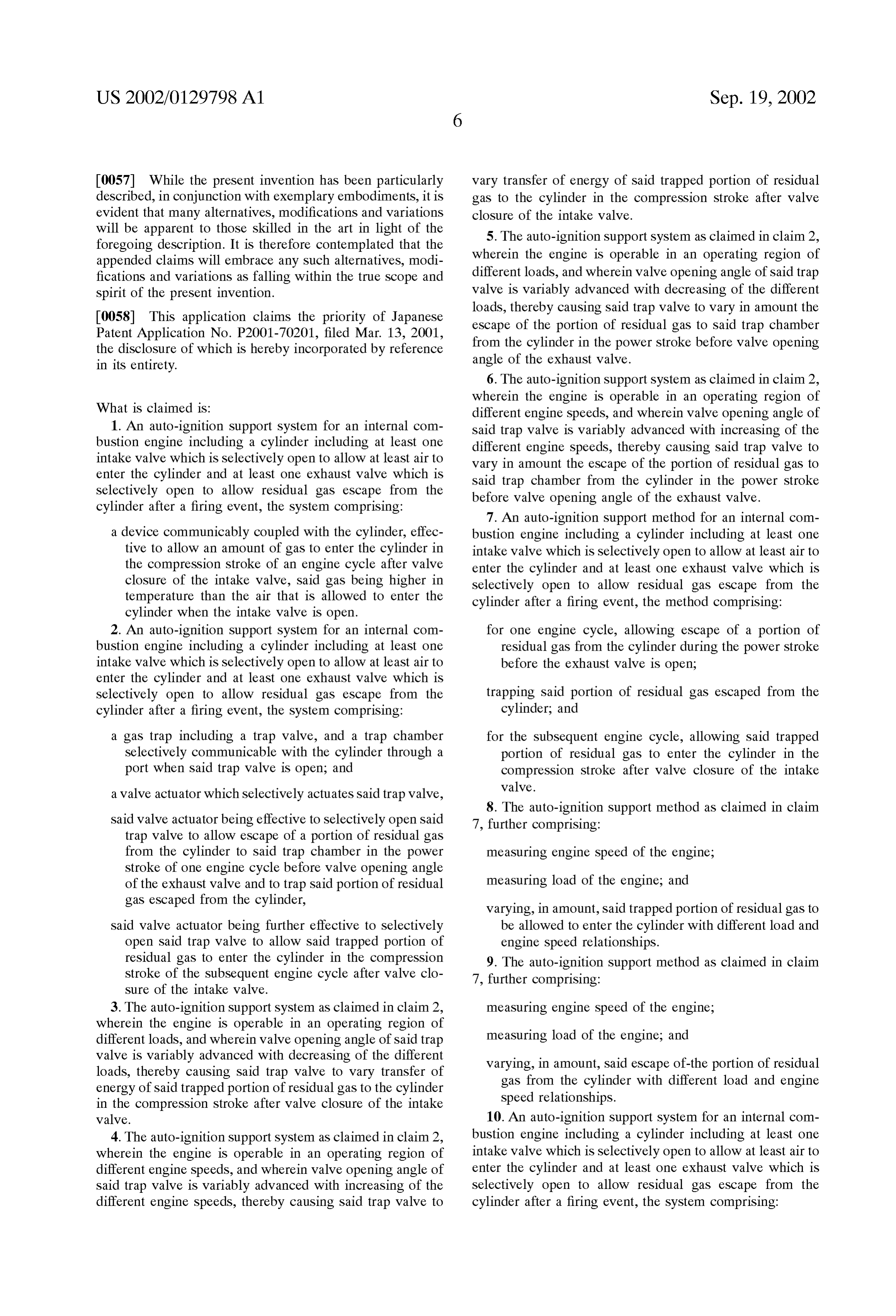
What is claimed is: different engine Speeds, and wherein Valve opening angle of 1. An auto-ignition Support System for an internal com Said trap valve is variably advanced with increasing of the bustion engine including a cylinder including at least one different engine Speeds, thereby causing Said trap valve to intake Valve which is Selectively open to allow at least air to vary in amount the escape of the portion of residual gas to enter the cylinder and at least one exhaust valve which is Said trap chamber from the cylinder in the power Stroke Selectively open to allow residual gas escape from the before valve opening angle of the exhaust valve. cylinder after a firing event, the System comprising:
7. An auto-ignition Support method for an internal com a device communicably coupled with the cylinder, effec bustion engine including a cylinder including at least one tive to allow an amount of gas to enter the cylinder in intake valve which is Selectively open to allow at least air to the compression Stroke of an engine cycle after valve enter the cylinder and at least one exhaust valve which is closure of the intake valve, Said gas being higher in Selectively open to allow residual gas escape from the temperature than the air that is allowed to enter the cylinder after a firing event, the method comprising: cylinder when the intake valve is open.
2. An auto-ignition Support System for an internal com for one engine cycle, allowing escape of a portion of bustion engine including a cylinder including at least one residual gas from the cylinder during the power Stroke intake valve which is selectively open to allow at least air to before the exhaust valve is open; enter the cylinder and at least one exhaust valve which is
Selectively open to allow residual gas escape from the trapping Said portion of residual gas escaped from the cylinder after a firing event, the System comprising: cylinder, and a gas trap including a trap valve, and a trap chamber for the Subsequent engine cycle, allowing Said trapped Selectively communicable with the cylinder through a portion of residual gas to enter the cylinder in the port when Said trap valve is open; and compression Stroke after valve closure of the intake valve.
a valve actuator which Selectively actuates Said trap valve, 8. The auto-ignition Support method as claimed in claim
Said valve actuator being effective to Selectively open Said 7, further comprising:
trap valve to allow escape of a portion of residual gas from the cylinder to Said trap chamber in the power measuring engine Speed of the engine; Stroke of one engine cycle before valve opening angle of the exhaust valve and to trap Said portion of residual measuring load of the engine; and gas escaped from the cylinder, varying, in amount, Said trapped portion of residual gas to said valve actuator being further effective to selectively be allowed to enter the cylinder with different load and open Said trap valve to allow Said trapped portion of engine Speed relationships.
residual gas to enter the cylinder in the compression 9. The auto-ignition Support method as claimed in claim Stroke of the Subsequent engine cycle after valve clo 7, further comprising:
Sure of the intake valve.
3. The auto-ignition Support System as claimed in claim 2, measuring engine Speed of the engine; wherein the engine is operable in an operating region of different loads, and wherein Valve opening angle of Said trap measuring load of the engine; and valve is variably advanced with decreasing of the different varying, in amount, Said escape of-the portion of residual loads, thereby causing Said trap valve to vary transfer of gas from the cylinder with different load and engine energy of Said trapped portion of residual gas to the cylinder Speed relationships.
in the compression Stroke after valve closure of the intake valve. 10. An auto-ignition Support System for an internal com 4. The auto-ignition Support System as claimed in claim 2, bustion engine including a cylinder including at least one wherein the engine is operable in an operating region of intake valve which is Selectively open to allow at least air to different engine Speeds, and wherein valve opening angle of enter the cylinder and at least one exhaust valve which is Said trap valve is variably advanced with increasing of the Selectively open to allow residual gas escape from the different engine Speeds, thereby causing Said trap valve to cylinder after a firing event, the System comprising:
Page 18
US 2002/0129798 A1 Sep. 19, 2002
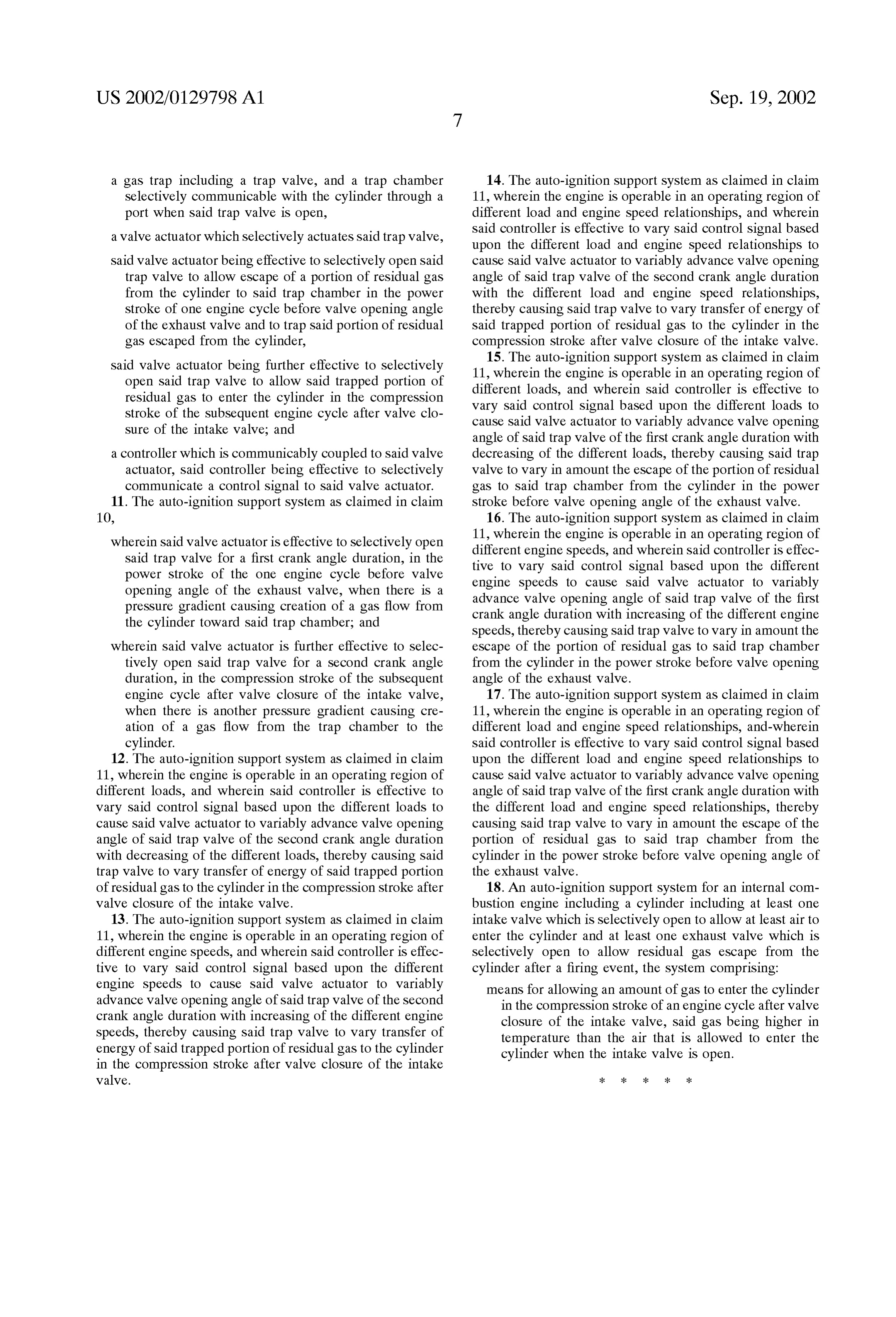
a gas trap including a trap valve, and a trap chamber 14. The auto-ignition Support System as claimed in claim Selectively communicable with the cylinder through a 11, wherein the engine is operable in an operating region of port when Said trap valve is open, different load and engine Speed relationships, and wherein a valve actuator which Selectively actuates Said trap valve, Said controller is effective to vary Said control Signal based upon the different load and engine Speed relationships to
Said valve actuator being effective to Selectively open Said cause Said valve actuator to variably advance valve opening trap valve to allow escape of a portion of residual gas angle of Said trap valve of the Second crank angle duration from the cylinder to Said trap chamber in the power with the different load and engine Speed relationships, Stroke of one engine cycle before valve opening angle thereby causing Said trap valve to vary transfer of energy of of the exhaust valve and to trap Said portion of residual Said trapped portion of residual gas to the cylinder in the gas escaped from the cylinder, compression Stroke after valve closure of the intake valve. said valve actuator being further effective to selectively 15. The auto-ignition Support System as claimed in claim open Said trap valve to allow Said trapped portion of 11, wherein the engine is operable in an operating region of residual gas to enter the cylinder in the compression different loads, and wherein said controller is effective to Stroke of the Subsequent engine cycle after valve clo vary Said control Signal based upon the different loads to Sure of the intake valve; and cause Said valve actuator to variably advance valve opening angle of Said trap valve of the first crank angle duration with a controller which is communicably coupled to Said valve decreasing of the different loads, thereby causing Said trap actuator, Said controller being effective to Selectively Valve to vary in amount the escape of the portion of residual communicate a control Signal to Said valve actuator. gas to Said trap chamber from the cylinder in the power 11. The auto-ignition Support System as claimed in claim Stroke before valve opening angle of the exhaust valve. 10, 16. The auto-ignition Support System as claimed in claim wherein Said valve actuator is effective to Selectively open 11, wherein the engine is operable in an operating region of Said trap valve for a first crank angle duration, in the different engine Speeds, and wherein Said controller is effec power Stroke of the one engine cycle before valve tive to vary Said control signal based upon the different opening angle of the exhaust valve, when there is a engine Speeds to cause Said valve actuator to variably preSSure gradient causing creation of a gas flow from advance valve opening angle of Said trap valve of the first the cylinder toward Said trap chamber; and crank angle duration with increasing of the different engine Speeds, thereby causing Said trap valve to vary in amount the wherein said valve actuator is further effective to selec escape of the portion of residual gas to Said trap chamber tively open said trap valve for a second crank angle from the cylinder in the power stroke before valve opening duration, in the compression Stroke of the Subsequent angle of the exhaust valve.
engine cycle after valve closure of the intake Valve, 17. The auto-ignition Support System as claimed in claim when there is another pressure gradient causing cre 11, wherein the engine is operable in an operating region of ation of a gas flow from the trap chamber to the different load and engine Speed relationships, and-wherein cylinder. Said controller is effective to vary Said control Signal based 12. The auto-ignition Support System as claimed in claim upon the different load and engine Speed relationships to 11, wherein the engine is operable in an operating region of cause Said valve actuator to variably advance valve opening different loads, and wherein said controller is effective to angle of Said trap valve of the first crank angle duration with vary Said control Signal based upon the different loads to the different load and engine Speed relationships, thereby cause Said valve actuator to variably advance valve opening causing Said trap valve to vary in amount the escape of the angle of Said trap valve of the Second crank angle duration portion of residual gas to Said trap chamber from the with decreasing of the different loads, thereby causing Said cylinder in the power Stroke before valve opening angle of trap valve to vary transfer of energy of Said trapped portion the exhaust valve.
of residual gas to the cylinder in the compression Stroke after 18. An auto-ignition Support System for an internal com valve closure of the intake valve. bustion engine including a cylinder including at least one 13. The auto-ignition Support System as claimed in claim intake valve which is Selectively open to allow at least air to 11, wherein the engine is operable in an operating region of enter the cylinder and at least one exhaust valve which is different engine Speeds, and wherein Said controller is effec Selectively open to allow residual gas escape from the tive to vary Said control signal based upon the different cylinder after a firing event, the System comprising: engine Speeds to cause Said valve actuator to variably means for allowing an amount of gas to enter the cylinder advance valve opening angle of Said trap valve of the Second in the compression Stroke of an engine cycle after valve crank angle duration with increasing of the different engine closure of the intake valve, Said gas being higher in Speeds, thereby causing Said trap valve to vary transfer of temperature than the air that is allowed to enter the energy of Said trapped portion of residual gas to the cylinder cylinder when the intake valve is open. in the compression Stroke after valve closure of the intake valve. k k k k k
Provenance
- Collection
- Patents citing this work
- Original assignee
- Nissan Motor Co Ltd
- Pages
- 18
- Method
- pdftotext (the PDF's own text layer) + pdftoppm 300dpi page scans
- Patent office record
- patents.google.com →
- Source
- Google Patents citing-documents table
- Inventors
- Tomonori Urushihara; Koichi Yamaguchi; Kazuya Hasegawa; Koudai Yoshizawa; Nissan Motor Co Ltd
- Published
- 2002-09-19
- Transcribed from
- patentimages.storage.googleapis.com →