patent · US1790870
Air heater and method op operating the same
3 February 1931
Page 1
Drawing sheet — no readable text.
Page 2
Drawing sheet — no readable text.
Page 3
Patented Feb. 3, 1931 1,790,870
UNITED STATES PATENT OFFICE
GREGORY D. MANTLE AND THEODORE W. MUNFORD, OF PITTSBURGH, PENNSYLVANIA, ASSIGNORS, BY MESNE ASSIGNMENTS, TO SURFACE COMBUSTION COMPANY, OF
TOLEDO, OHIO, A CORPORATION OF NEW YORK
AR BEATER, AND METHOD OF ORERATING TEESAME
Application filed July 12, 1927. Serial No. 205,105.
This invention relates to air heaters and erably higher. Therefore, in the operation to a method of operating the same, and re of this type of heater also, it has been the lates more particularly to an air heater practice to introduce atmospheric air into the wherein a novel arrangement is provided for combustion chamber in excess of the theo 5 controlling the flame temperature and a retical amount needed to depress the flame. 55 method by means of which the flame temper temperature so that the products of combus atures can be controlled with a high degree tion entering the heater will be at a temper of efficiency. s ature of approximately 1800° F. This in Warious types of air heaters have been de troduction of cooling air to depress the flame 10 veloped for use in conjunction with drying temperature, as above pointed out, is not 60 or similar operations where the air delivery economical because the temperature of the temperature may vary from 200° F. to pos cooling air is raised from atmospheric tem sibly 900° F. Such heaters as ordinarily perature to approximately 1800° F. and a provided are constructed of steel, and the safe large amount of this heat is wasted when the 15 working temperature must be kept, below products of combustion pass out of the heat 65 approximately 900°F. In the case of direct er. However, with this particular type of fired heaters, the fuel must be burned with an heater the efficiency is considerably higher excess of air so that the products of com than with the usual type of heater. bustion will be cooled to the safe operating According to the present invention, it is 20 temperature prior to their entering the heat proposed to remove some of the products 70 er. This is not economical owing to the fact of combustion from the heater at some point that the air required to dilute the products in the passage of these products therethrough of combustion sufficiently to lower the tem and recirculate these products of combustion perature to a safe operating point must be through the combustion chamber whereby 25 heated from the normal atmospheric tem only substantially the theoretical amount of 75 perature to the temperature of operation, air need be supplied the combustion chamber which is a difference of several hundred de through the burner while the flame tempera grees. Consequently, a considerable amount ture will be depressed by the recirculation of of the fuel is wasted in merely heating the 80 excess volume of cooling air. Most of this some ideal of the products of combustion. Under 80 operating conditions the discharge of heat is lost with the discharge of the prod products of combustion from the heater will ucts of combustion from the heater.
Certain types of heaters have been de oretical volume ofequivalent be substantially combustion to just the the gases. In this veloped wherein it is possible to operate 35 safely, without interruption, at a temper Way practically all the sensible heat is utilized 85 and the efficiency of the heater increased. Ac ature as high as 1800° F. Such a heater is cording shown, for instance, in Patent No. 1,518,258, proposedto tothecombine present invention it is further dated December 9, 1924, granted to F. A. products of combustionthe recirculation of with a heater capa
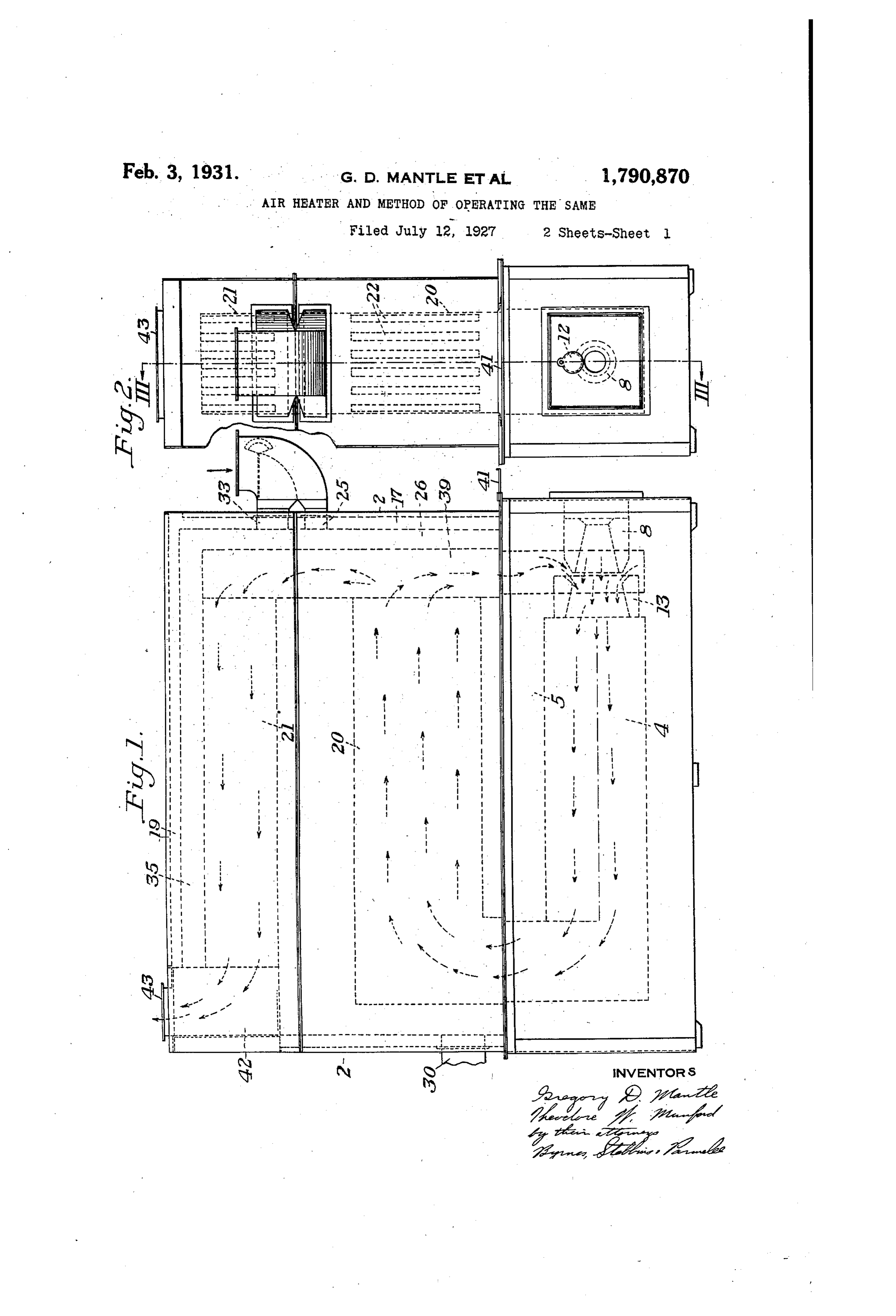
Fahrenwald. In this type of heater the flow ble of operating at temperatures around O of air to be heated is so divided as to secure 90 the greatest possible cooling effect so that the 1800 F. so that the minimum amount of products of combustion can be circulated products of combustion need be recirculated through the heater at much higher temper to secure the highest maximum efficiency. atures. However, none of the common fuels The invention may be readily understood 95 may be burned with approximately the the by reference to the accompanying drawings, oretical amount of air required for their in which combustion so as to get a flame temperature Figure 1 represents a side elevation of a as low as 1800° F. With just the theoretical heater and combustion unit embodying my amount of air, the flame temperature of invention, the arrows indicating the direction 0 ordinary fuels, such as gas and oil, is consid of flow of the products of combustion;
Page 4
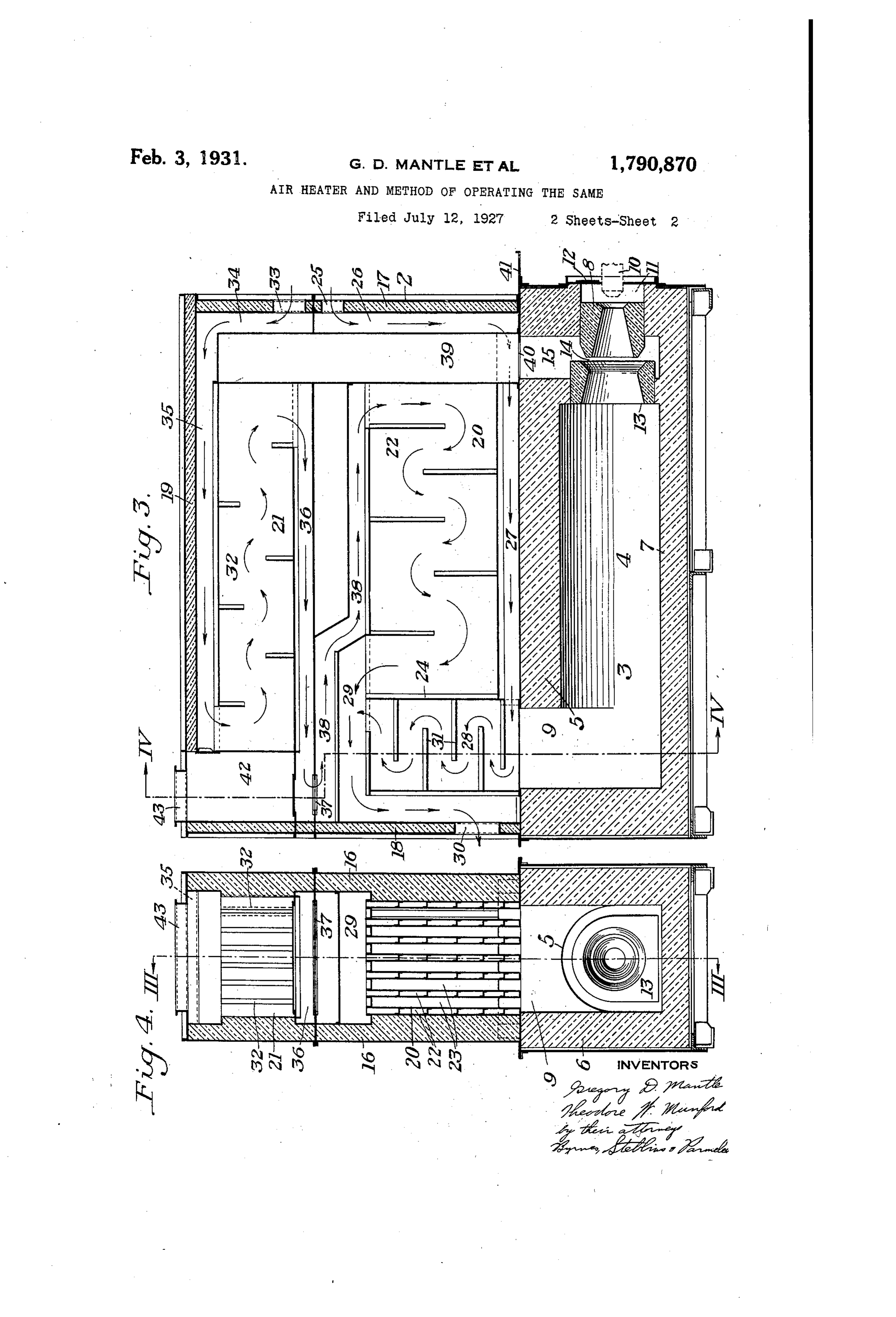
Figure 2 is an end view of the heater and end side of the elements 32, and from the rear combustion unit shown in Figure 1; of the passage 35 the air flows into the Figure 3 is a vertical longitudinal section several air circulating elements 32. The air in the plane of line III-III of Figures 2 and flows lengthwise along the elements 32 and at the front of these elements it discharges O 4, the arrows indicating the course of travel into a manifold 36 extending horizontally of the air through the heater; and along the bottom of the elements 32. The Figure 4 is a vertical cross section on the air from the manifold 36 flows through a line IV-IV of Figure 3.
In the drawings, 2 designates the heater port 37 into a horizontal passage 38 in the 75 0 and 3 is a combustion chamber at the bottom lower section of the heater. From the pas of the heater unit. The combustion chamber sage 38 the air flows into the forwardmost has a longitudinally extending passage 4 ends of the air circulating members 22. The therein with a refractory top wall 5, side walls air travels through the members 22 toward 6 and a bottom 7. At the front end of the the cross walls 24 thereof and discharges into 5 combustion chamber is a burner block, desig the manifold 29 to mix with the air flowing
nated generally as 8. At the rear end of the bers from the passages 28. The ends of the mem combustion chamber is a vertical passage 9 22 extend across the vertical passage 9 that communicates with the combustion E.e in the combustion chamber so that the prod ucts of combustion from the combustion circulating passages in the heater.
20 burner block 8 has a burner 10 disposed in chamber will rise between the members 22 85 front of a passage 11. In front of the burner and flow horizontally between these members . block 8 is a throat 13, and the member 13 to the vertical manifold 39 at the forward is located sufficiently far in front of the mem most end of the members 22. The bottom of ber 8 to provide an annular opening 14 be the manifold 39 communicates through a port 90 25 tween the two members. The annular space 40 controlled by a damper 41 with the ver 14 communicates with a vertical passage 15 tical passage 15 at the forward end of the communicating with the interior of the combustion chamber. The manifold 39. ex heater, as hereinafter more fully described. tends upwardly across the forward ends of The heater 2 has side walls 16, a front wall the air-heating elements 32 in the upper sec 30 17, a rear wall 18, and a top 19. There are tion. The products of combustion travel hor 95 preferably two sections to the heater, a lower izontally from the upper end of the manifold one 20 and an upper one 21. The lower sec 39 between the elements 32 to the discharge tion 20 has a plurality of spaced apart air passage 42 and out the discharge opening 43. heating elements 22 with gas circulating pas In Figure 3 the arrows indicate the direc 35 sages 23 therebetween. The air-heating ele tion of air circulation, and in Figure 1 the 100 ments 22 are formed of heat resistant steel arrows indicate the direction in which the alloy, and the arrangement is such that air products of combustion circulate. - is circulated through the elements 22 while burned In the operation of the heater the fuel is hot gases of combustion are circulated around in the combustion chamber 4 and the 40 the outside of the elements 22 through the hot gases rise through the passage 9 between passages 23 and thus effect an exchange of the rear ends of the air heaters 22. The gases heat between the gases and the air. The ele then flow horizontally forward between the ments 22 have a cross wall 24 therein which members 22 to the vertical manifold or pas separates the interior space in the air pas sage 39. It will be apparent that the rear 10 45 sages, as best shown in Figure 3, to provide ends of the members 22 over the passage 29 separate passages for the flow of air in dif are subject to the most intense heat. They ferent parts of the air heater. The heater is are therefore cooled by leading air directly provided with air inlet ports arranged to give from the port 25 through the passages 26 a divided flow of air through the heater. One and 27 to the vertical passage 28. With this 50 of these ports, designated 25, opens into a arrangement relatively cold airflows through vertical passage 26 along the front wall 17 thattheportion of the heater which is subjected in the heater. From the passage 26 the air to highest temperatures. By this ar- . flows along a horizontal passage 27 in one rangement also, the temperature of the prod side of each of the elements 22. The passages ucts of combustion is lowered considerably 55 27 open into the vertical passage 28 at one end almost as soon as the products of combustion 20 of the element 22. From the passage 28 the enter the heater, and the portions of the ele heated air flows through a manifold 29 to the ments 22 forwardly of the cross barrier 24 hot air outlet 30. Bafiles 31 are provided in are subject to less intense temperatures. the vertical passage 28. The upper section Therefore, the air circulated through the ) 21 of the air heater is provided with a plu forward portions of the members 22 is first rality of air circulating elements 32. Air heated in the upper section of the heater and then introduced into the forward ends enters the upper section of the heater through of port 33 in the front wall of the heater. From forthea elements 22. The general arrangement divided flow of air through the air 30 the port 33 it flows into a vertical passage 55 34, then along a horizontal passage 35 at one heater as described is not new, and is shown
Page 5
in the said Patent No. 1518,258, dated De utilize all heat in the gases above 250 F. in cember 9, 1924, granted to F. A. Fahrenwald, addition to eliminating the loss occasioned by hereinbefore referred to. the use of cold air for depressing the flame There is a drop in the temperature of the temperature.
gases between the point where they leave While the invention has been specifically 70 the combustion chamber at 9 and the mani described in connection with a preferred con fold 39. The aspirating action of the burner struction thereof, it will be understood that tends to draw the gases of combustion from the invention is not confined to the particular the passage 39 down through the port 40 into form of heater shown, or to the particular de () the passage 15 and from the passage 15 sign of combustion chamber, and that va 75 through the mixer passage 14, where the rious changes and modifications may be made products of combustion are mingled with the therein within the contemplation of our in combustible mixture to depress the flame tem vention and under the scope of the appended perature in the combustion chamber. The claim.
products of combustion drawn from the We claim: 80 manifold 39 through the port 40 and into Apparatus for heating air including a the burner, while being relatively hot, are combustion chamber having a gas discharge still considerably below the temperature of passage and having a combusted gas intake the flame when burned with the theoretical passage, a burner in the combustion chamber 2) amount of air. Thus, the products of com adapted to draw gases from the combusted bustion introduced in this manner into the gas intake passage and discharge them into combustion chamber serve to lower the flame the combustion chamber, an air heater hav temperature so that excessively hot gases will ing air circulating elements therein with gas not flow from the combustion chamber into circulating passages therebetween, one end the air heater. At the same time, only ap of the airheater being disposed over the gas 90 proximately the theoretical amount of air discharge passage of the combustion cham need be introduced into the combustion ber, the gas circulating passages between the chamber through the burner, and the dis air circulating elements communicating with charge of products of combustion from the the said gas discharge passage of the combus outlet passage 43 should, under ideal oper tion chamber, means for circulating cold air ating conditions, be only the theoretical vol thirough that portion of the elements most ume of gases. nearly adjacent the gas discharge passage By thus drawing partially cooled products of the combustion chamber, means whereby of combustion from the heater back into the the air will flow through the remaining por 35 combustion chamber, and properly regulat tion of the air heating elements in a direc 00 ing the volume of flow by means of damper tion counter to the circulation of gases be 41, accurate control of the flame temperature tween the airheating elements, and a passage is secured and practically all of the available connecting the combusted gas intake of the heat is utilized. In using the recirculation combustion chamber with the gas circulating O of products of combustion in a heater having passages in the heater at a point remote from 05 a divided air flow, the most efficient condi the point where the gases of combustion enter tions of operation can be secured with the the heater.
greatest economy of fuel. In testimony whereof we have hereunto set The adaptation of our invention to a two our hands.
4. section heater has particular importance. If GREGORY D. MANTLE. O the theoretical volume of gases of combustion THEODORE. W. MUNFORD. were discharged after they had passed through the first section, the temperature thereof would be so high as to occasion a con 50 siderable loss of heat. If the gases were re circulated from the discharge end of the sec ond section, they would be cooled to too great an extent for the most efficient operation.
According to our invention, the gases are 55 recirculated from an intermediate point in 2: the heater, that is, the point between the two sections, at which time they are relatively hot, while the theoretical volume of gases cir.
culates through the upper section to further deliver up heat to the air. By the use of . Sufficient transfer Surface in the upper heater section, the gases may be cooled to a relative ly low temperature, say about 250°F, under normal operating conditions before they are discharged. This means that we actually
Provenance
- Collection
- Cited prior art
- Original PDF
- patentimages.storage.googleapis.com →
- Pages
- 5
- Method
- pdftotext (the PDF's own text layer) + pdftoppm 300dpi page scans
- Source
- Google Patents bibliographic record
- Granted
- 1931-02-03
- Transcribed from
- patentimages.storage.googleapis.com →