patent · US120057
Improvement in magneto-electric machines
17 October 1871
Page 1
Drawing sheet — no readable text.
Page 2
Drawing sheet — no readable text.
Page 3
Drawing sheet — no readable text.
Page 4
Drawing sheet — no readable text.
Page 5
UNITED STATES
'ZENOBE THEOPHILE GRAMME
PATENT OFFICE
AND EARDLEY LOUIS CHARLES D'TVERNOIS, OF
PARIS, FRANCE.
IMPROVEMENT IN MAGNETO-ELECTRIC MACHINES.
Specification forming part of Letters Patent No. 120,057, dated October 17, 1871.
To all whom tt may concern:
Be it known that we, ZENOBE THEOPHILE
Grama and EARDLEY LOUIS CHARLES D’IVER- NOIs, of Paris, in the Empire of France, have invented Improvements in Magneto-Electric Machines; and we do hereby declare that the following is a full and exact description thereof, reference being had to the accompanying drawing and to the letters of reference marked thereon, corresponding parts being marked in the various figures as much as possible by the same letters.
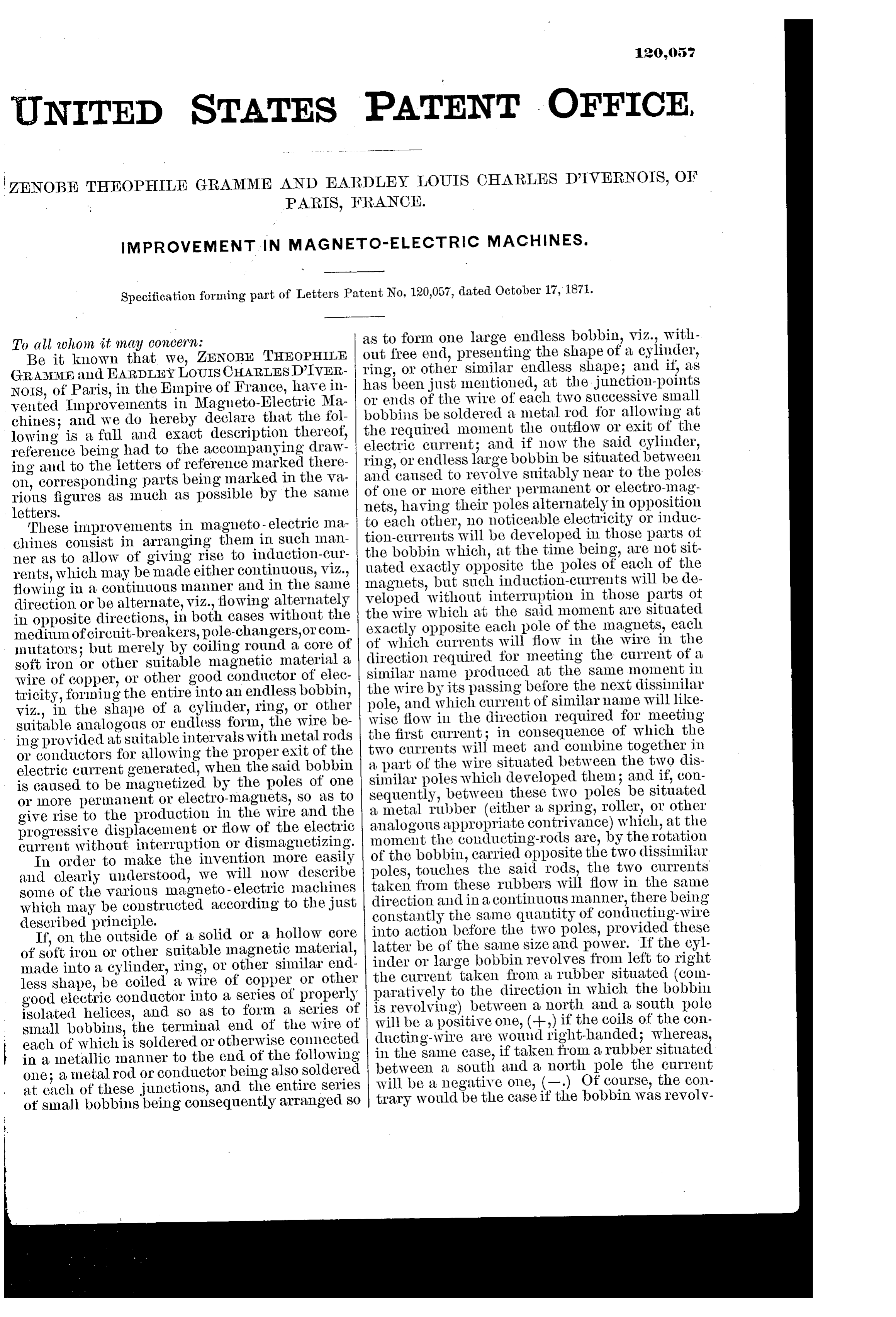
These improvements in magneto -electric machines consist in arranging them in such manner as to allow of giving rise to induction-currents, Which may be made either continuous, V1zZ., flowing in a continuous manner and in the same direction or be alternate, viz., lowing alternately in opposite directions, in both cases without the medium of cireuit-breakers, pole-changers,or commutators; but merely by coiling round a core of soft iron or other suitable magnetic material a wire of copper, or other good conductor of electricity, forming the entire into an endless bobbin, viz., in the shape of a cylinder, ring, or other suitable analogous or endless form, the wire being provided at suitable intervals with metal rods or conductors for allowing the proper exit of the electric current generated, when the said bobbin is caused to be magnetized by the poles of one or more permanent or electro-magnets, SO as to give rise to the production in the wire and the progressive displacement or flow of the electric current without interruption or dismagnetizing.
In order to make the invention more easily and clearly understood, we will now describe some of the various magneto-electric machines which may be constructed according to the just described principle.
If, on the outside of a solid or a hollow core of soft iron or other suitable magnetic material, made into a cylinder, ring, or other similar endless shape, be coiled a wire of copper or other good electric conductor into a series of properly isolated helices, and so as to form a series of small bobbins, the terminal end of the wire of each of which is soldered or otherwise connected in a metallic manner to the end of the following one; a metal rod or conductor being also soldered
at each of these junctions, and the entire series ot small bobbins being consequently arranged so
as to form one large endless bobbin, viz., without free end, presenting the shape of a eylinder, ring, or other similar endless shape; and if, as has been just mentioned, at the junction-points or ends of the wire of each two successive small bobbins be soldered a metal rod for allowing at the required moment the outflow or exit of the electric current; and if now the said cylinder, ring, or endless large bobbin be situated between and caused to revolve suitably near to the poles: of one or more either permanent or electro-magnets, having their poles alternately in opposition to each other, no noticeable electricity or induction-currents will be developed in those parts ot the bobbin which, at the time being, are not situated exactly opposite the poles of each of the magnets, but such induction-currents will be developed without interruption in those parts ot the wire which at the said moment are situated exactly opposite each pole of the magnets, each of which currents will flow in the wire in the direction required for meeting the current of a similar name produced at the same moment in the wire by its passing before the next dissimilar pole, and which current of similar name will likewise flow in the direction required for meeting the first current; in consequence of which the two currents will meet and combine together in a part of the wire situated between the two dissimilar poles which developed them ; and if, consequently, between these two poles be situated a metal rubber (either a spring, roller, or other analogous appropriate contrivance) which, at the moment the conducting-rods are, by the rotation of the bobbin, carried opposite the two dissimilar poles, touches the said rods, the two currents taken from these rubbers will flow in the same direction and in a continuous manner, there being constantly the same quantity of conducting-wire into action before the two poles, provided these latter be of the samme size and power. If the cylinder or large bobbin revolves from left to right the current taken from a rubber situated (comparatively to the direction in which the bobbin is revolving) between a north and a south pole will be a positive one, (+,) if the coils of the conducting-wire are wound right-banded; whereas, in the same case, if taken from a rubber situated between a south and a north pole the current will be a negative one, (—.) Of course, the contrary would be the case if the bobbin was revolv-
Page 6
ing in the opposite direction, or if the helix of the conducting-wire was a left-handed one.
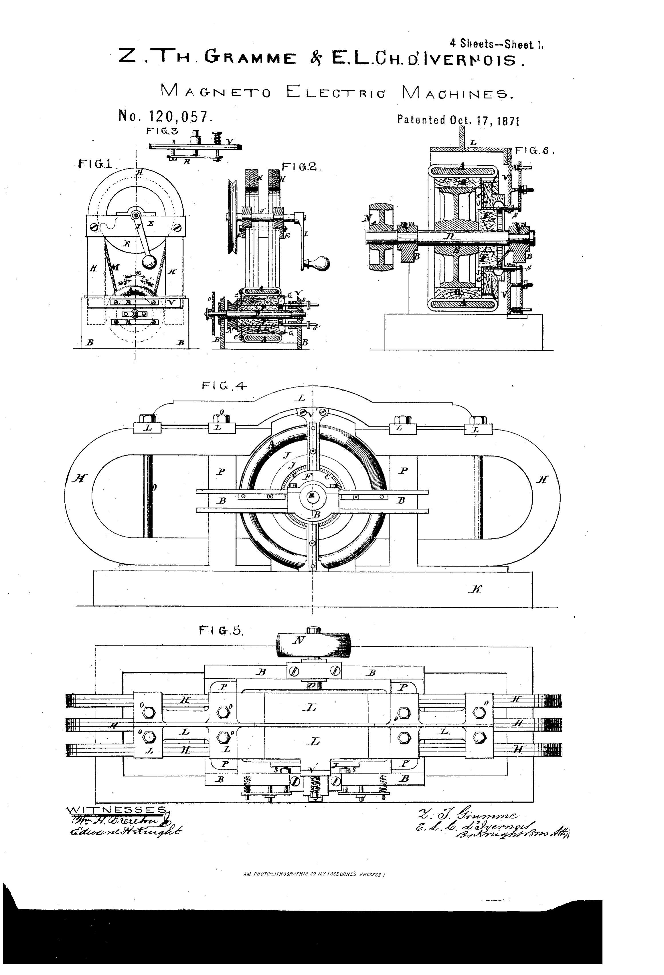
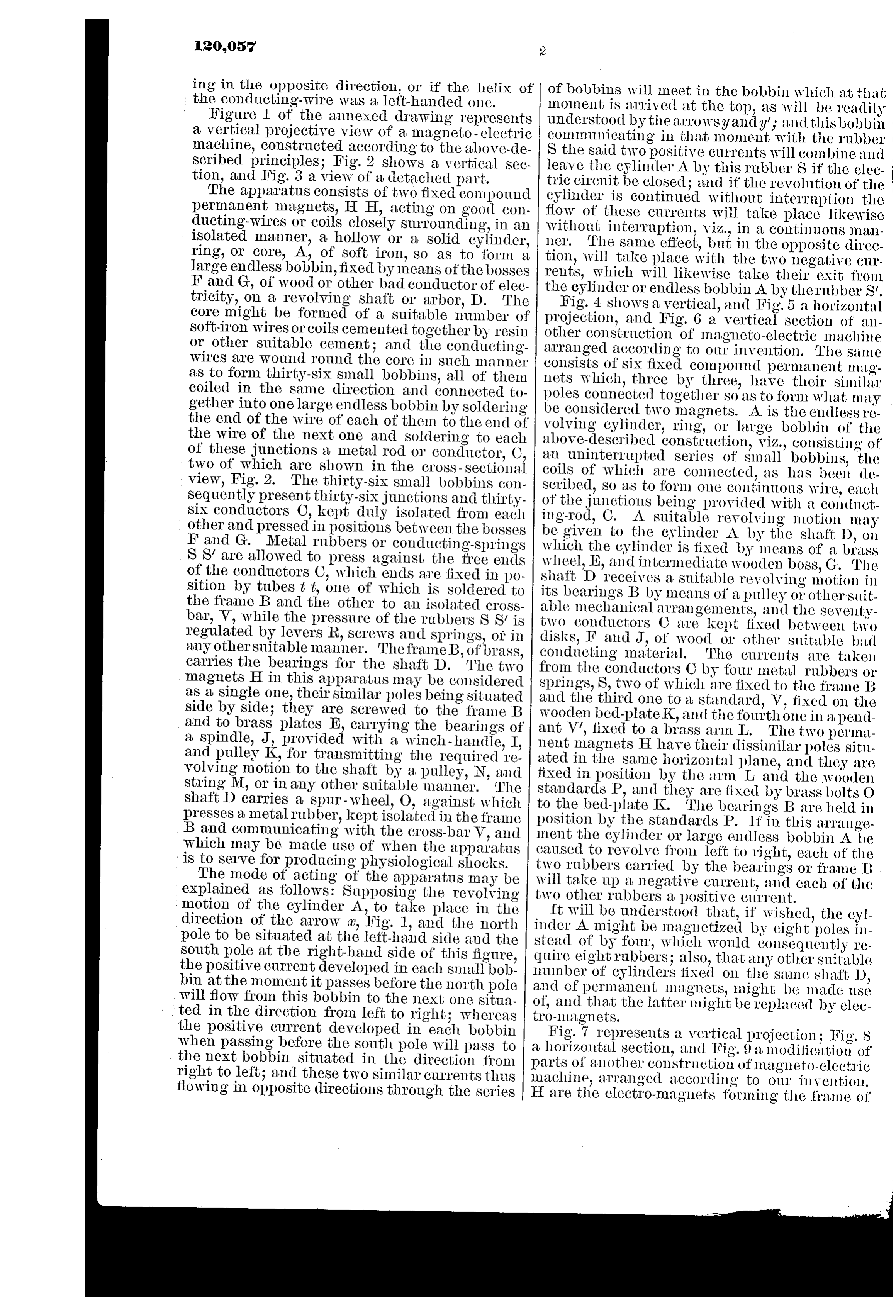
Figure 1 of the annexed drawing represents a vertical projective view of a magneto-electric machine, constructed according to the above-described principles; Fig. 2 shows a vertical section, and Fig. 3 a view of a detached part.
The apparatus consists of two fixed compound permanent magnets, H H, acting on good eonducting-wires or coils closely surrounding, in an isolated manner, a hollow or a solid cylinder, ring, or core, A, of soft iron, so as to form a large endless bobbin, fixed by means of the bosses F and G, of wood or other bad conductor of eleetricity, on a revolving shaft or arbor, D. The core might be formed of a suitable number of soft-iron wires or coils cemented together by resin or other suitable cement; and the conductingwires are wound round the core in such manner as to form thirty-six small bobbins, all of them coiled in the same direction and connected together into one large endless bobbin by soldering the end of the wire of each of them to the end of the wire of the next one and soldering to each of these junctions a metal rod or conductor, C, two of which are shown in the cross-sectional view, Fig. 2. The thirty-six small bobbins consequently present thirty-six junctions and tl Lirtysix conductors ©, kept duly isolated from each other and pressed in positions between the bosses F and G. Metal rubbers or conducting-springs S S’ are allowed to press against the free ends of the conductors C, which ends are fixed in position by tubes ¢ ¢, one of which is soldered to the frame B and the other to an isolated crossbar, V, while the pressure of the rubbers S 8’ is regulated by levers R, screws and springs, of in any othersuitable manner. TheframeB, of b "ASS, carries the bearings for the shaft D. The two magnets H in this apparatus may be considered as a single one, their similar poles being situated side by side; they are screwed to the frame B and to brass plates E, carrying the bearings of a spindle, J, provided with a winch-handle, I, and pulley K, for transmitting the required revolving motion to the shaft by a pulley, N, and string M, or in any other suitable manner. The shatt D carries a spur- wheel, O, against which presses a metal rubber, kept isolated in the frame B and communicating with the cross-bar V, and which may be made use of when the apparatus is to serve for producing physiological shocks.
The mode of acting of the apparatus may be explained as follows: Supposing the revolving
‘motion of the cylinder A, to take place in the direction of the arrow «, Fig. 1, and the north pole to be situated at the left-hand side and the south pole at the right-band side of this figure, the positive current developed in each small bobbin at the moment it passes before the north pole will flow from this bobbin to the next one situated in the direction from left to right 3; Whereas the positive current developed in each bobbin when passing before the south pole will pass to the next bobbin situated in the direction from right to left; and these two similar currents thus flowing in opposite directions through the series
of bobbins will meet in the bobbin which at that moment is arrived at the top, as will be readily understood by the arrowsy andy’; and this bobbin communicating in that moment with the rubber S the said two positive currents will combine and leave the cylinder A by this rubber 8 if the electrie circuit be closed; and if the revolution of the cylinder is continued without interruption the flow of these currents will take place likewise without interruption, viz., in a continuous manner, The same effect, but in the opposite direction, will take place with the two negative currents, which will likewise take their exit from the eylinder or endless bobbin A. by therubber 8’,
Hig. 4 shows a vertical, and Fig. 5 a horizontal projection, and Fig. 6 a vertical section of another construction of magneto-electric machine arranged according to our invention. The sume consists of six fixed compound permanent magnets which, three by three, have their similar poles connected together so as to form what may be considered two magnets. A is the endless revolving cylinder, ring, or large bobbin of the above-described construction, viz., consisting of an uninterrupted series of small bobbins, the coils of which are connected, as has been described, so as to form one continuous wire, cach of the junctions being provided with a conducting-rod, C. A. suitable revolving motion may be given to the eylinder A by the shatt D, on which the cylinder is fixed by means of a brass wheel, E, and intermediate wooden boss, G. ‘The shaft D receives a suitable revolving motion in its bearings B by means of a pulley or other-suitable mechanical arrangements, and the seventytwo conductors C are kept fixed between two disks, F and J, of wood or other suitable bad conducting material. The currents are taken from the conductors © by four metal rubbers or springs, 8, two of which are fixed to the frame B and the third one toa standard, V, fixed on the wooden bed-plate K, and the fourth one in a pendant V’, fixed to a brass arm L. The two permanent Inagnets H have their dissimilar poles situated in the same horizontal plane, and they are fixed in position by the arm L and the wooden standards P, and they are fixed by brass bolts O to the bed-plate K. The bearings B are held in position by the standards P. I’ in this arrangement the cylinder or large endless bobbin A be caused to revolve from left to right, each of the two rubbers carried by the bearings or frame B will take up a negative current, aud each of the two other rubbers a positive current.
ft will be understood that, if wished, the cylinder A might be magnetized by eight poles instead of by four, which would consequently require eight rubbers; also, that any other suitable number of cylinders fixed on the same shaft D, and of permanent magnets, ight be made use of, and that the latter might be replaced by elec-
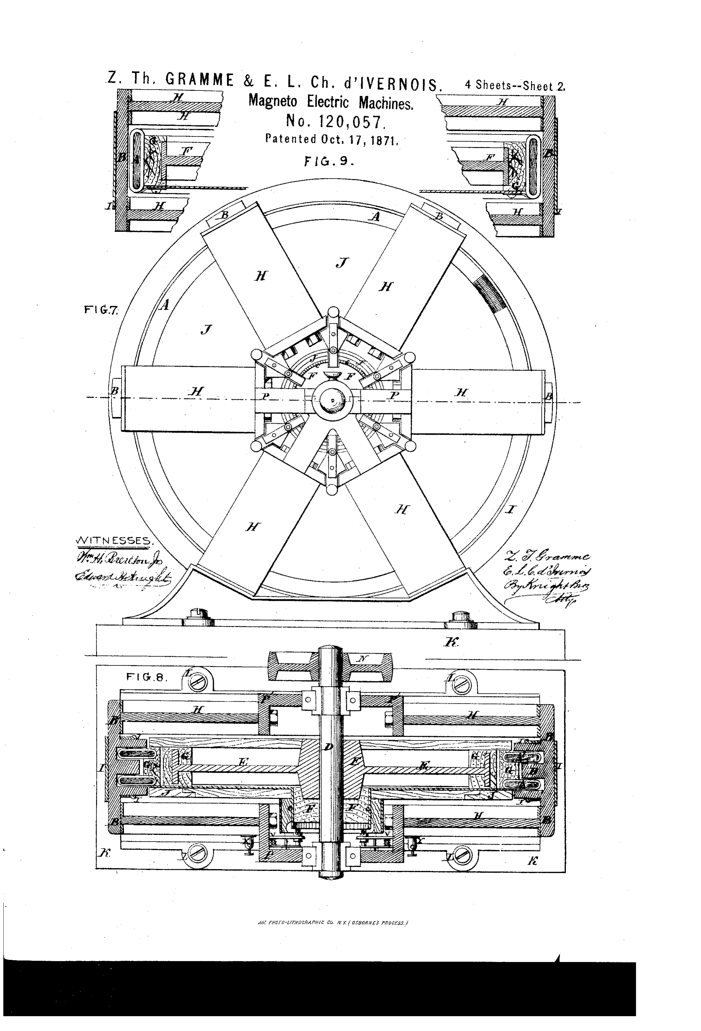
Fig. 7 represents a vertical projection; Fig. $ a horizontal section, and Fig. 9 a modifieation of parts of another construction of magneto-electric machine, arranged according to our invention. H are the clectro-magnets forming the frame of
Page 7
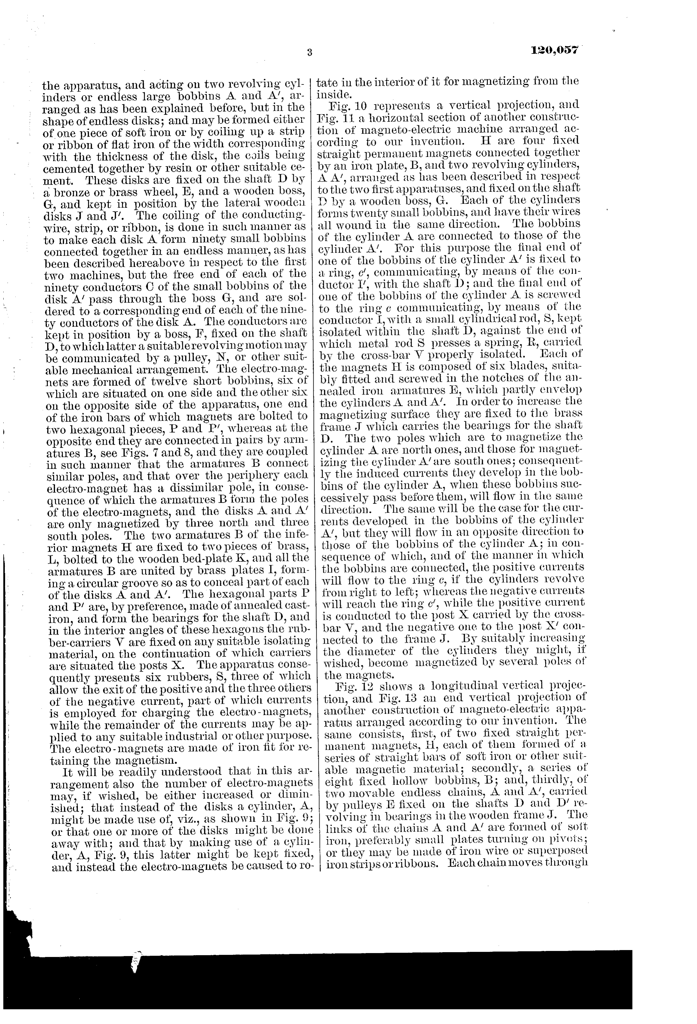
the apparatus, and acting on two revolving cylinders or endless large bobbins A and A’, arranged. as has been explained before, but in the shape of endless disks; and may be formed either of one piece of soft iron or by coiling up a strip or ribbon of flat iron of the width corresponding with the thickness of the disk, the coils being cemented together by resin or other suitable cement. These disks are fixed on the shaft D by a bronze or brass wheel, E, and a wooden boss, G, and kept in position by the lateral wooden disks Jand J’. The coiling of the conductingwire, strip, or ribbon, is done in such manner as to make each disk A form ninety small bobbins connected together in an endless manuer, as has been described hereabove in respect to the first two machines, but the free end of each of the ninety conductors C of the small bobbins of the disk A’ pass through the boss G, and are soldered to a corresponding end of each of the ninety conductors of the disk A. The conductors are kept in position by a boss, F, fixed on the shaft D, to which latter a suitablerevolving motion may be communicated by a pulley, N, or other suitable mechanical arrangement. The electro-magnets are formed of twelve short bobbins, six of which are situated on one side and the other six on the opposite side of the apparatus, one end of the iron bars of which magnets are bolted to two hexagonal pieces, P and P’, whereas at the opposite end they are connected in pairs by armatures B, see Figs. 7 and 8, and they are coupled in such manner that the armatures B connect similar poles, and that over the periphery each electro-magnet has a dissimilar pole, in consequence of which the armatures B fori the poles of the electro-magnets, and the disks A and A’ are only magnetized by three north and three south poles. The two armatures B of the inferior magnets H are fixed to two pieces of brass, L, bolted to the wooden bed-plate K, and all the armatures B are united by brass plates I, forming a circular groove so as to conceal part of each of the disks A and A’. The hexagonal parts P and P/ are, by preference, made of annealed castiron, and form the bearings for the shaft D, and in the interior angles of these hexagons the rubber-carriers V are fixed on any suitable isolating material, on the continuation of which carriers are situated the posts X. The apparatus consequently presents six rubbers, S, three of which allow the exit of the positive and the three others of the negative current, part of which currents is employed for charging the electro-magnets, while the remainder of the currents may be applied to any suitable industrial or other purpose. The electro-magnets are made of iron fit for retaining the magnetism.
It will be readily understood that in this arrangement also the number of electro-magnets may, if wished, be either increased or diminished; that instead of the disks a cylinder, A, might be made use of, viz., as shown in Fig. 9; or that one or more of the disks might be done away with; and that by making use of a cylinder, A, Fig. 9, this latter might be kept fixed, and instead the electro-magnets be caused to ro-
tate in the interior of it for magnetizing from the inside.
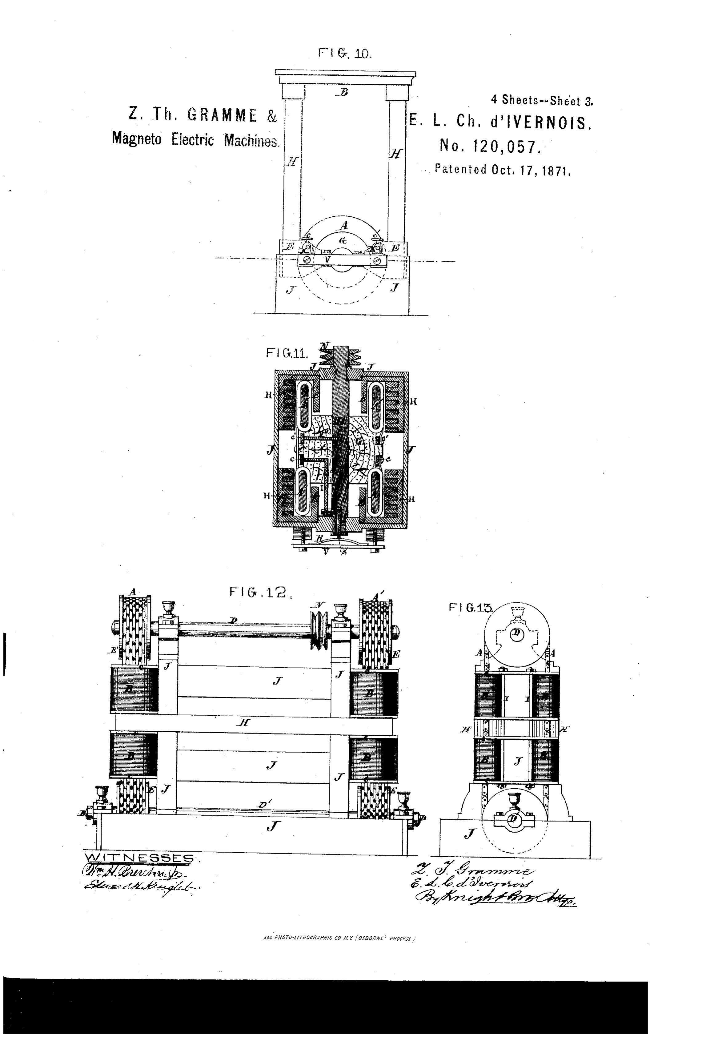
Fig. 10 represents a vertical projection, and Fig. 11 a horizontal section of another construction of magneto-electric machine arranged according to our invention. H are fowr fixed straight permanent magnets connected together by an iron plate, B, and two revolving cylinders, A A‘, arranged as has been described in respect tothe two first apparatuses, and fixed onthe shaft D by a wooden boss, G. Each of the cylinders forms twenty small bobbins, and have their wires all wound in the same direction. ‘The bobbins of the cylinder A are connected to those of the cylinder A’. For this purpose the final end of one of the bobbins of the cylinder A’ is fixed to a ring, ¢, communicating, by means of the conductor I’, with the shaft D; and the final end of one of the bobbins of the cylinder A is screwed to the ring ¢ communicating, by means of the conductor L, with a small cylindrical rod, 8, kept isolated within the shaft D, against the end of which metal rod S presses a spring, R, carried by the cross-bar V properly isolated. Each of the magnets H is composed of six blades, suitably fitted and serewed in the notches of the annealed iron armatures BE, which partly envelop the cylinders A and A’. In order to increase the magnetizing surface they are fixed to the brass frame J which carries the bearings for the shaft D. The two poles which are to magnetize the cylinder A are north ones, and those for magnetizing the cylinder A/are south ones; consequently the induced currents they develop in the bobbins of the cylinder A, when these bobbins successively pass before them, will flow in the same direction. The same will be the case for the currents developed in the bobbins of the cylinder A’, but they will flow in an opposite direction to those of the bobbins of the cylinder A; in consequence of which, and of the manner in which the bobbins are connected, the positive currents will flow to the ring ¢, if the cylinders revolve from right to left; whereas the negative currents will reach the ring ¢, while the positive current is conducted to the post X carried by the crossbar V, and the negative one to the post X/ connected to the frame J. By suitably increasing the diameter of the cylinders they might, if wished, become magnetized by several poles of the magnets.
Fig. 12 shows a longitudinal vertical projection, and Fig. 13 an end vertical projection of another construction of magneto-electric apparatus arranged according to our invention. The same consists, first, of two fixed straight permanent magnets, H, each of them formed of a series of straight bars of soft iron or other suitable magnetic material; secondly, a series of eight fixed hollow bobbins, B; and, thirdly, of two movable endless chains, A and A’, carried by pulleys E fixed on the shafts D and D’ revolving in bearings in the wooden frame J. The links of the chains A and A! are formed of soit iron, preferably small plates turning on pivots; or they may be made of iron wire or superposed iron stripsorvibbons. Each chainmoves through
Page 8
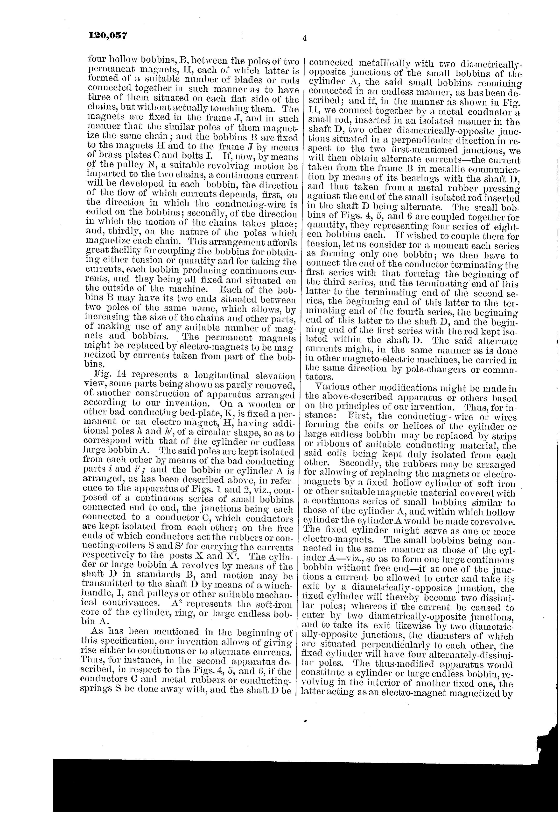
four hollow bobbins, B, between the poles of two permanent magnets, H, each of which latter is formed of a suitable number of blades or rods connected together in such manner as to have three of them situated on each flat side of the chains, but without actually touching them. The magnets are fixed in the frame J, and in such manner that the similar poles of them magnetize the same chain; and the bobbins B are fixed to the magnets H and to the frame J by means of brass plates C and bolts I. If, now, by means of the pulley N, a suitable revolving motion be imparted to the two chains, a continuous current will be developed in each bobbin, the direction of the flow of which currents depends, first, on the direction in which the conducting-wire is coiled on the bobbins; secondly, of the direction in which the motion of the chains takes place; and, thirdly, on the nature of the poles which magnetize each chain. This arrangement atfords great facility for coupling the bobbins for obtain- ‘ing either tension or quantity and for taking the ciurents, each bobbin producing continuous currents, and they being all fixed and situated on the outside of the machine. Each of the bobbins B may have its two ends situated between two poles of the same name, which allows, by increasing the size of the chains and other parts, of making use of any suitable number of magnets aud bobbins. The permanent magnets might be replaced by electro-magnets to be magnetized by currents taken from part of the bobbins,
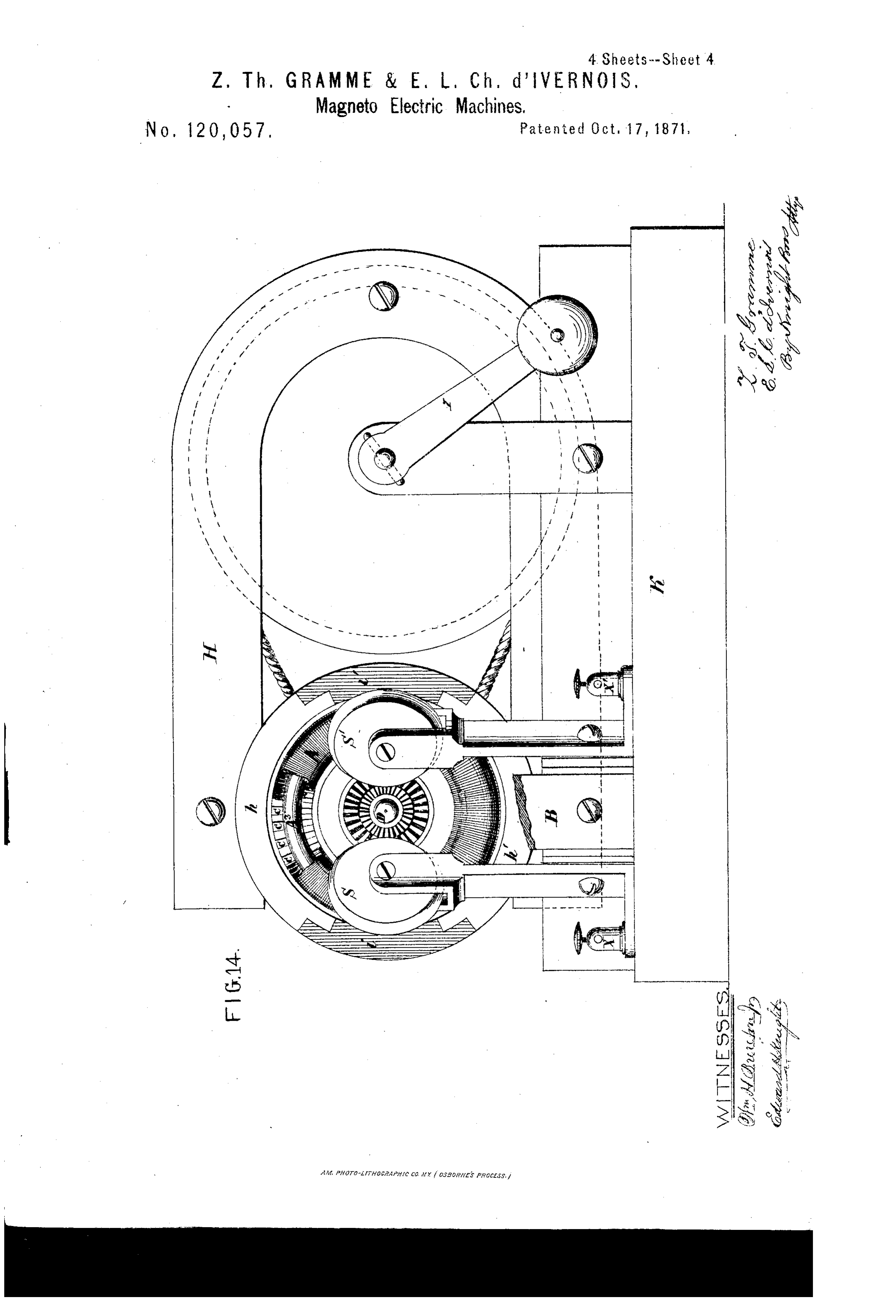
Fig. 14 represents a longitudinal elevation view, some parts being shown as partly removed, of. another construction of apparatus arranged according to our invention. On a wooden or other bad conducting bed-plate, K, is fixed a permanent or an electro-magnet, H, having additional poles & and A’, of a circular shape, so as to correspond with that of the cylinder or endless large bobbinA. The said poles are kept isolated from cach other by means of the bad conducting parts ¢ and i’; and the bobbin or cylinder A is arranged, as has been described above, in reference to the apparatus of Figs. 1 and 2, viz., composed of a continuous series of small bobbins connected end to end, the junctions being each connected to a conductor ©, which conductors are kept isolated from each other; on the free ends of which conductors act the rubbers or connecting-rollers S and S/ for carrying the currents respectively to the posts X and X’. ‘The cylinder or large bobbin A revolves by means of the shaft D in standards B, and motion may be transmitted to the shaft D by means of a winchhandle, I, and pulleys or other suitable mechanical contrivances. A? represents the soft-iron core of the cylinder, ring, or large endless bobbin A.
As has been mentioned in the beginning of this specification, our invention allows of giving rise either to continuous or to alternate currents, Thus, for instance, in the second apparatus described, in respeet to the Figs. 4, 5, and 6, if the conductors C and metal rubbers or conductingsprings S be done away with, and the shatt D be
connected metallically with two diametricallyopposite junctions of the sinall bobbins of the cylinder A, the said small bobbins remaining connected in an endless manner, as has been described; and if, in the manner as shown in Fig. 11, we connect together by a metal conductor a small rod, inserted in an isolated manner in the shaft D, two other diametrically-opposite junetions situated in a perpendicular direction in respect to the two first-mentioned junctions, we will then obtain alternate curvents—the current taken from the frame B in metallic communication by means of its bearings with the shaft D, and that taken from a metal rubber pressing against the end of the small isolated rod inserted in the shaft D being alternate. The small bobbins of Figs. 4, 5, and 6 are coupled together for quantity, they representing four series of cighteen bobbins each. If wished to couple them for tension, let us consider tor a moment each series as forming only one bobbin; we then have to connect the end of the conductor terminating the first series with that forming the beginning of the third series, and the terminating end of this latter to the terminating end of the second series, the beginning end of this latter to the terminating end of the fourth series, the beginning end of this latter to the shaft D, and the beginning end of the first series with the rod kept isolated within the shaft D. The said alternate currents might, in the same manner as is done in other magneto-electric machines, be carried in the same direction by pole-changers or commutators.
Various other modifications might be made in the above-described apparatus or others based on the principles of owr invention. Thus, for instance: First, the conducting - wire or wires forming the coils or helices of the cylinder or large endless bobbin may be replaced by strips or ribbons of suitable conducting material, the said coils being kept duly isolated from each other. Secondly, the rubbers may be arranged for allowing of replacing the magnets or electromagnets by a fixed hollow cylinder of soft iron or other suitable magnetic material covered with & continuous series of small bobbins similar to those of the cylinder A, and within which hollow cylinder the cylinder A would be made torevolve. The fixed cylinder might serve as one or more electro-magnets. The small bobbins being connected in the same manner ag those of the eylinder A—viz., so as to form one large continous bobbin without free end—if at one of the junetions a current be allowed to enter and take its exit by a diametrically -opposite junction, the fixed cylinder will thereby become two dissimilar poles; whereas if the current be caused to enter by two diametrically-opposite junctions, and to take its exit likewise by two diametrically-opposite junctions, the diameters of which are sitnated perpendicularly to each other, the fixed cylinder will have four alternately-dissimilar poles. The thus-modified apparatus would coustitute a cylinder or large endless bobbin, revolving in the interior of another fixed one, the latter acting as an electro-magnet magnetized by
Page 9
a portion of the currents taken from the rubbers of the first one, and it would be the magnetism of the wire of the fixed bobbin re-enforced by the magnetism of its iron core, which would act on the revolving bobbin. A suitable number of the small bobbins constituting the large fixed bobbin might be replaced by a stout iron bar or wire so as to carry the poles of the iron core nearer to the movable large bobbin. Thirdly, several movable cylinders or large bobbins might be applied on the same shaft, one of which bobbins might serve for giving off continuous currents to be made use of for magnetizing the electro-magnets which replace the permanent ones; whereas the remainder of the bobbins might give off alternate currents to be made use of for the production of electric light or for other industrial, physiological, or other purposes. Fourthly, the general arrangement of our apparatus may also be modified in various manners; thus, for instance, instead of causing the cylinder or large bobbin A of the apparatus of Figs. 1 and 2 to revolve, a magnet might be caused to revolve at the inside or at the outside of this bobbin.
What we consider to be novel and original, and therefore more particularly claim as our invention, is—
1. The employment, in magneto-electric machines, of one or more cylinders, rings, or large endless bobbins arranged and constructed in the
manner as has been above described, viz., made into a circular or other suitable endless shape, and consisting of a series of small bobbins or wires enveloping a core of soft iron or other good magnetic material, and connected together end to end in a continuous series, the said endless large bobbin or bobbins or cylinders situated between or in opposition to the poles of fixed or movabie permanent or electro-magnets, for the purpose of allowing the production of continuous induction currents in the conducting-wires, strips, or ribbons of brass or other good conducting metal enveloping the magnetic material, in which wires, strips, or ribbous a continuous displacement of the magnetism takes place without demagnetizing.
», The arrangements described for allowing of giving rise to alternate or opposite instead of continuous currents.
3. Lhe general arrangement and combination of parts of the various above-described magneto-electric apparatus to be employed for any industrial, physiological, or other purposes for which electric currents may be made use of, substantially as described and iNustrated in the annexed drawing and for the purposes set down.
ZENOBE THEOPHILE GRAMME.
EARDLEY LOUIS CHARLES D’'IVERNOIS.
Witnesses:
A. G. BRADE,
AUGUSTE MEDARD.
Provenance
- Collection
- Cited prior art
- Original PDF
- patentimages.storage.googleapis.com →
- Pages
- 9
- Method
- pdftoppm 300dpi + tesseract 5 (eng)
- Source
- Google Patents bibliographic record
- Granted
- 1871-10-17
- Transcribed from
- patentimages.storage.googleapis.com →