patent · US1174602
Steam-accumulator.
7 March 1916
Page 1
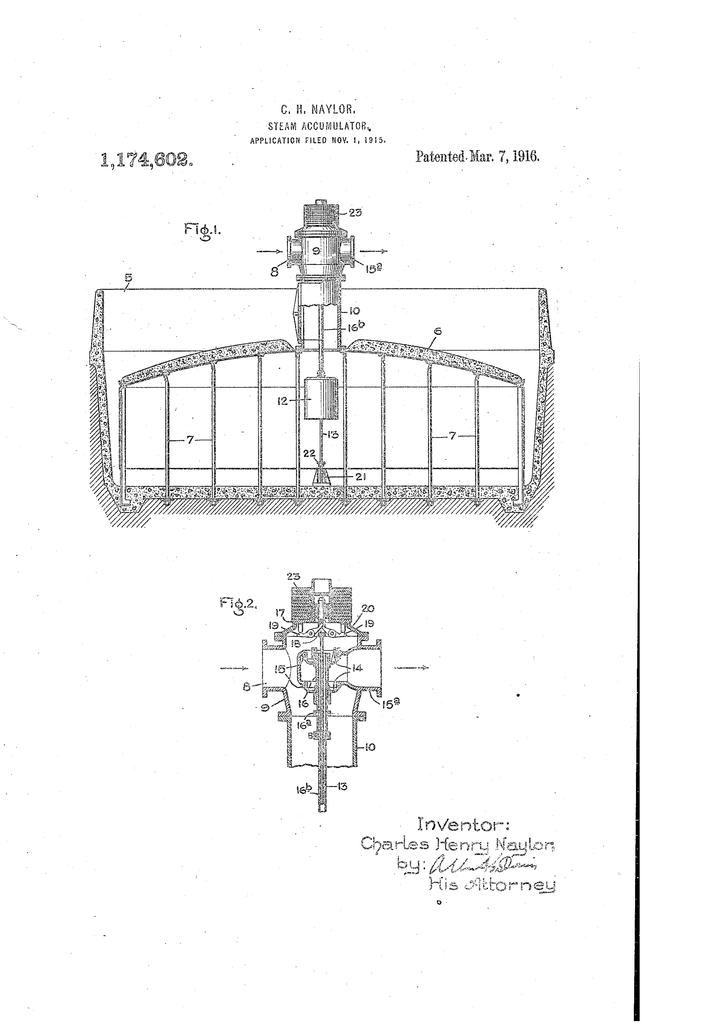
Drawing sheet — no readable text.
Page 2
UNITED STATE
CEARLES BEARY NAYLOR, or RUCRY, ENG: SEOs, (ENER.E., E.E.C.C. COISPAN2, A CC3RECRAS3 5,7 E3,
SES.&ti-AgCUA. (JSA: S.
racetacriterro
2, 34,602. Specification of Letters Satet, i?ateated Ria. , 1916. 'plication filed ovember 3, 3A5. Seria. No. 59,083.
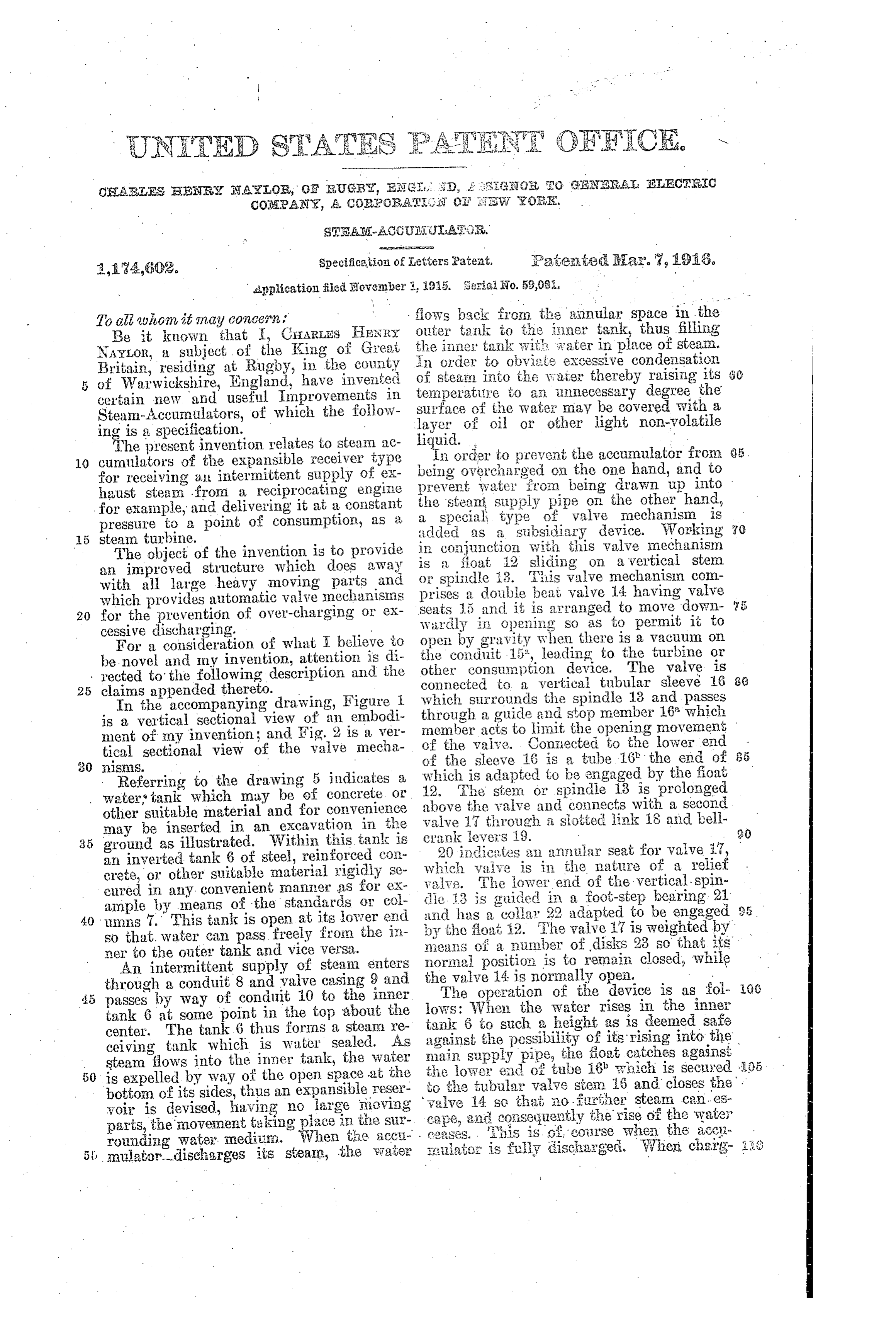
To all vion, it may concen: flows hack from the annular space in the Be it known that I, CHARLES HENRY Outer tank to the illner tank, thus filling NAYLOR, a subject of the King of Great, the illes' tank with water in place of steam. Britain, residing at Rugby, in the county in stealin order to obviate excessive condensation 5 of Warwickshire, England, have invented of into the Saier thereby raising its temperature to an unnecessary degree the certain new sand useful improvements in surface
Steam-Accumulators, of which the follow layer ofof oil the water may be covered with a or other light non-volatile
The present invention relates to steam ac 10 cumulators of the expansible receiver type beingIn order to prevent
Overcharged on the the accumulator one hand, fromto 3.
and for receiving as intermittent supply of ex prevent wate; from being drawn up into haust steam from a reciprocating engine for example, and delivering it at a constant the steam supply pipe on the other hand, a special type of valve mechanism is pressure to a point of consumption, as a added as a subsidiary device. Working 5 steam turbine.
The object of the invention is to provide in conjunction with this valve mechanism an improved structure which does away is spindle a fioat 12 sliding on a vertical stem with all large heavy moving parts and or prises a i3. This valve mechanism com double beat valve 14 having valve which provides automatic valve mechanisms 20 for the prevention of over-charging or ex Seats 5 and it is arranged to move down cessive discharging. - Wardly if opening so as to permit it to For a consideration of what believe to opei by gravity when there is a vacuum on be novel and my invention, attention is di the conduit 15, leading to the turbine or other consumption device. The valve is rected to the following description and the connected to a vertical tubular sleeve 16 8. 25 claims appended thereto.
In the accompanying drawing, Figure which Surrounds the spindle 13 and passes is a vertical sectional view of an embodi through a guide and stop member 16, which ment of my invention; and Fig. 2 is a ver of member acts to limit the opening movement, tical sectional view of the valve mecha the vaive. Contected to the lower end 30 inistas. . . of the sleeve 16 is a tube 16 the end of Referring to the drawing 5 indicates a which is adapted to be engaged by the foat, 12. The stem or spindle 13 is prolonged water tank which may be of concrete or above other suitable material and for convenience valve 1thethrough valve and connects with a second may be inserted in an excavation in the crank evers 19. a siotted link 18 and beli 90 35 ground as illustrated. Within this tank is an inverted tank 6 of steel, reinforced co which 20 indicates an angular seat for valve it, crete, or other suitable material rigidly Se vais' 2. valve is in the nature of a relief cured in any convenient manner as for ex die i3 is guided inenda foot-step
The lower of the vertical spin bearing 21 ample by means of the standards or col and has a collar 22 adapted to be engaged 40 umns . This tank is open at its over end so that, water can pass freely from the in by the floaf i2. The valve 7 is weighted by: means of a number of disks 23 so that its ner to the outer tank and vice versa. normal position is to remain closed, while An intermittent supply of steam enters the valve 14 is normally open. through a conduit 8 and yalve casing 9 and The operation of the device is as fol. passes by way of conduit 10 to the inner lows: When tank 6 at some point in the top about the tank 6 to suchthea height Water rises in the inner as is deemed safe center. The tank 6 thus forms a steaIK re ceiving tank which is water sealed. As against the possibility of its rising into the main supply pipe, the float catches against;
steam flows into the inner tank, the water the lower end of tube i8 wich is secured 3.35 50 is expelled by way of the open space at the bottom of its sides, thus an expansible reser valve 14 to the tubular valve stem 6 and closes the . yoir is devised, having noiarge rioving cape, 2 ad soconsequently that, no further steam can.es the rise of the water parts, the movement taking place in the Sur 5: rounding water. EredititsY. steam, the water issuiator is fully discharged.when
When tige acci. . his is of course the acci.
When chairg 8
Page 3
ing takes place and the water descends so cally preventing over-charging and exces low in the inner vessel that there is danger sive discharging.
of the oil on its surface being driven out at 2. A steam accumulator comprising a the annular space at the bottom of its sides, stationary water tank, a fixed inverted steam the float then catches against the stop 22 receiving tank therein, an inlet conduit and 70 and the slotted link 18 comes against the an exit conduit for conveying steam to and ends of the bell-crank levers 19 causing the from the receiving tank, a valve in the exit other ends of these levers to open the relief conduit, and means for closing said valve valve 17. The incoming steam is then re when the steam has been discharged to a pre 0 lieved to atmosphere and the further de determined extent. 75 scent of the water in the accumulator is ar 3. A steam accumulator comprising a rested. This of course is when the accumu stationary water tank, a fixed inverted steam lator is fully charged. receiving tank therein, an inlet conduit and While the specific means shown for sup an exit conduit for conveying steam to and porting the inner tank is now considered by from the receiving tank, a relief valve, and 80 me as being preferable, it will be understood means for automatically opening said valve that my invention is not limited to this ar to prevent overcharging of the accumulator. rangement, and that any other suitable 4. A steam accumulator comprising a means may be used. stationary water tank, a fixed inverted steam 20 The volume of the outer tank may be receiving tank therein, an inlet conduit and 85 about twice the volume of the inner tank so an exit conduit for conveying steam to and that when the inner tank is empty, the an from the receiving tank, a valve in the exit nular space in the water tank is full to the conduit, a sten connected to it, and a float top. This would occur if the top of the which engages the stem to close the valve inner tank is on a level with the top of the when the water reaches a predetermined 90 outer tank. The pressure variation in this high level in the steam chamber. case would be from a point below atmos 5. A steam accumulator comprising a phere to a point above atmosphere, about stationary water tank, a fixed inverted steam equal either way. If it is desired that the receiving tank therein, an inlet conduit and pressure be constantly above atmosphere in an exit conduit for conveying steam to and 95 the inner vessel, it would be necessary to from the receiving tank, a relief valve, a fix the inner vessel in such a position in the spindle connected to it, and a float which tank that the top of it is considerably be engages the spindle to open the relief valve low the top of the outer tank, and the inner when the Water reaches a predetermined 35 tank would always be submerged even when low level in the steam chamber. 00 fully discharged and full of water. The 6. The combination with a steam accumu whole of the surface of the inner tank should lator comprising a stationary water tank be insulated with some heat non-conducting and a fixed inverted steam receiving tank material which is at the same time water re therein, the lower edge of which is sealed 40 sisting. - by the water, said steam receiving tank hav 05 The above described arrangement, it will ing an admission conduit and an exit con be seen, provides a structure in which there duit, of a normally open valve in the exit are no heavy moving parts and which there conduit, a normally closed relief valve in fore necessitates no strong guides or Wearing the steam receiving tank, and means con parts: at the same time however it provides trolled by the level of the Water in the steam 10 an efficient automatic mechanism for the pre receiving tank for closing the first named vention of overcharging or excessive dis valve when such water reaches a predeter charging. mined high level and for opening the relief In accordance with the provisions of the valve when it reaches a predetermined lov, 50 patent statutes, I have described the prin level. 5 ciple of operation of my invention, together 7. A steam accumulator comprising a with the apparatus which now consider to stationary water tank, a fixed inverted steam represent the best embodiment thereof; but receiving tank therein, an inlet conduit and I desire to have it inderstood that the ap an exit conduit for conveying steam to and 5 paratus shown is only illustrative, and that from the receiving tank, a relief valve in 20 the invention can be carried out by other the steam receiving tank having a stem, a means, such as come within the scope of the valve in the exit conduit having a stem, and appended claims. means controlled by the level of the water What I claim as new and desire to secure in the steam receiving tank which engages
by1.Letters Patent of the United States, is:- said stems to open the relief valve and to 25 A steam accumulator comprising a close the valve in the exit conduit.
stationary water tank, a fixed inverted steam 8. A. steam accumulator comprising a receiving tank therein, conduit, means for stationary water tank, a fixed inverted steam conveying steam to and from the receiving receiving tank therein, an inlet conduit and 65 tank, and valve mechanisa for autoniati an exit conduit for conveying steam to and
Page 4
biased to open position in the exit conduit, 5 from the receiving tank, a relief valve in and a float controlled by the level of the the steam receiving tank having a stem, a water in the steam receiving tank for open valve in the exit conduit having a tubular ing the relief valve when the steam receiv stem which surrounds the other stem and ing tank becomes overcharged, and for clos 20 terminates short of the end thereof, a collar ing the exit valve when the steam receiving on the first named stem and a float which is tank becomes over-discharged. guided by such stem and is located between In witness whereof, I have hereunto set the collar and the end of the tubular stem. my hand this 14th day of October 1915.
9. A steam accumulator comprising a stationary water tank, a fixed inverted steam CHARLES HENRY NAYLOR. . . receiving tank therein, an inlet conduit and Witnesses:
an exit conduit for conveying steam to and CHARLEs. H. FullLER, from the receiving tank, a relief valve J. A. FosTER. biased to closed position in such tank, a valve
Provenance
- Collection
- Cited prior art
- Original PDF
- patentimages.storage.googleapis.com →
- Filed
- 1915-11-01
- Pages
- 4
- Method
- pdftotext (the PDF's own text layer) + pdftoppm 300dpi page scans
- Source
- Google Patents bibliographic record
- Granted
- 1916-03-07
- Inventors
- Charles Henry Naylor; General Electric Co
- Transcribed from
- patentimages.storage.googleapis.com →