patent · US10480401B2
Implosion enabled engine of exothermic type in explosive system (IEEX-EX) employing a safe pipe system (SPS) and other safety devices
19 November 2019
Page 1 — bibliographic record
United States Patent ( 10 ) Patent No.: US 10,480,401 B2 Barthakur (45 ) Date of Patent: Nov. 19 , 2019 (54 ) IMPLOSION ENABLED ENGINE OF (58) Field of Classification Search EXOTHERMIC TYPE IN EXPLOSIVE CPC .... FO2B 43/00 ; FO2M 21/0293; FO2M SYSTEM ( IEEX -EX ) EMPLOYING A SAFE 21/0206 ; FO2M 21/0227 ; YO2T 10/32 PIPE SYSTEM (SPS) AND OTHER SAFETY See application file for complete search history .
DEVICES
( 71) Applicant: Jitendra Kumar Barthakur, New U.S. PATENT DOCUMENTS Delhi (IN )
(72) Inventor: Jitendra Kumar Barthakur, New 4,389,981 A 6/1983 Meyer Delhi ( IN ) ( Continued ) ( * ) Notice : Subject to any disclaimer, the term of this FOREIGN PATENT DOCUMENTS patent is extended or adjusted under 35 WO WO - 2003 /069142 8/2003 U.S.C. 154 (b ) by 242 days . WO WO - 2011 / 125064 10/2011 (21) Appl. No.: 14 / 888,082 OTHER PUBLICATIONS ( 22 ) PCT Filed : Oct. 21 , 2014 International Search Report and Written Opinion for PCT/IN2014 /
( 86 ) PCT No .: PCT/ IN2014 /000672 (Continued ) $ 371 ( c )( 1 ), Primary Examiner Hung Q Nguyen (2 ) Date : Oct. 29 , 2015 (74 ) Attorney, Agent, or Firm Morrison & Foerster LLP
PCT Pub . Date :May 7 , 2015 (57) ABSTRACT The present subject matter discloses the concept of multiple (65 ) Prior Publication Data engine heads for one cylinder operating as Serially Operat US 2016/0230652 A1 Aug. 11 , 2016 ing Internal Combustion (SOIC ) engine using Safe Pipe System (SPS) and other integrated systems, viz ., Interim ( 30 ) Foreign Application Priority Data Storage of Gas (ISG ) and Pre -Disposal Exhaust Treatment (PDET). SPS is in the form of a chamber having a main
pipeline segregated into different interconnected SGC seg
Aug. 4 , 2014 ( IN ) 2203 /DEL /2014 ments allowing and disrupting the flow of substantially pure
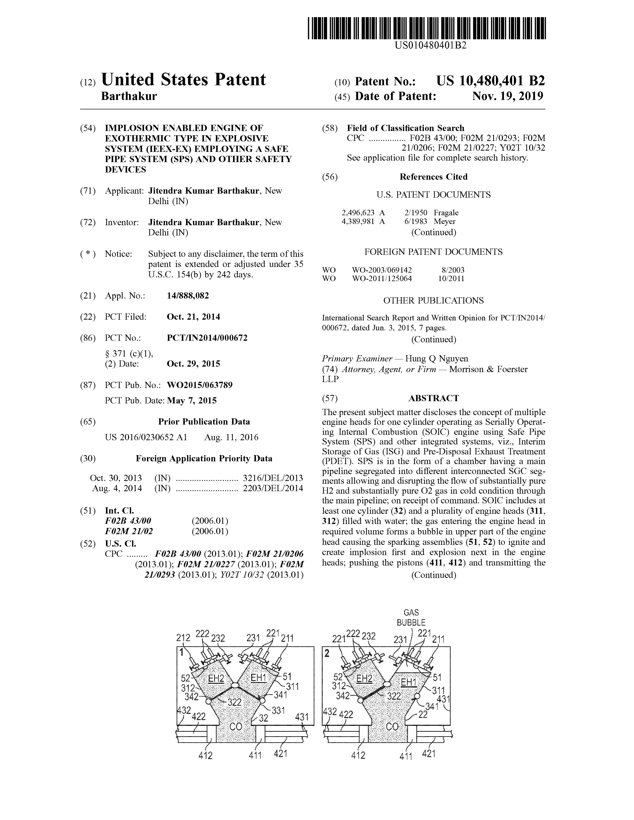
H2 and substantially pure O2 gas in cold condition through the main pipeline ; on receiptof command . SOIC includes at (51) Int. Ci. least one cylinder (32 ) and a plurality of engine heads (311 , FO2B 43/00 ( 2006.01) 312 ) filled with water; the gas entering the engine head in FO2M 21/02 ( 2006.01) required volume forms a bubble in upper part of the engine (52) U.S. Cl. head causing the sparking assemblies (51 , 52) to ignite and CPC F02B 43/00 ( 2013.01 ); F02M 21/0206 create implosion first and explosion next in the engine (2013.01); F02M 21/0227 (2013.01 ); F02M heads; pushing the pistons (411 , 412 ) and transmitting the 21/0293 ( 2013.01 ); YO2T 10/32 (2013.01) (Continued )
GAS
BUBBLE
342 -341 342 322 311
432* 422 -331 431 -341
Page 2
force of explosion to the crankshaft assembly (431 , 432 ) to produce tor or the force of explosion generated by IEEX - EM expelling the water outof cylinder ( 32 ) with high pressure being used for rotating turbine or for throwing projectile to produce energy.
8 Claims, 7 Drawing Sheets
9/2004 Eichelberger
2002/0046773 A1 * 4/2002 Bishop B63B 25/14
OTHER PUBLICATIONS
International Preliminary Report on Patentability for PCT/IN2014 /
* cited by examiner
Page 3
Closed 2 2 Closed
Inert
Gas Inlet Chamber of Inert Gas IN Gas to Cylinder Head 2 2 Closed Through Other Gas Inlet Similar Units A SGC - SGC - SGC *****
FIG . 1A
Phase II and Phase III Inert Gas Outlet
Inert
Gas
to Cylinder Head
Gas Inlet Through Other A SGC - SGC SGC Similar Units Closed Water Closed DISABLED Shut
FIG . 1B
Open 2 2 Open
Inert Inert Gas Outlet
2 2 2 Open Phase III 1 Gas to Cylinder Head
Gas Inlet Through Other Closed
SGCSISGCSISGCClosed Similar Units
DISABLED
Open
FIG . 1C
Page 4
Phase IV and V Inert Gas Outlet
Inert Chamber of Inert Gas
Gas Inlet 2 2 2 Phase V
Gas to Cylinder Head
Gas Inlet
A B Similar Units
DISABLED
Closed Water Closed Step 1
FIG . 1D
Closed 2 2 Closed pogod
Chamber of Inert Gas InertGas Outlet Inert Gas
Inlet 2 Closed 2 Phase V Gas Inlet
A Similar Units open Open ENABLED Shut
FIG . 1E
SPS
Inputfrom Main
Storage of Gas
Outlet leading
Page 5
Drawing sheet — no readable text.
Page 6
GAS
BUBBLE
312 311 312 EH1 -51
-322 431
CO CO
FIG . 4A
BUBBLE EXPLOSION 52 EH2 51 52 EH2 231 311 312 342 322 EH1 311 EH1
-32 22
FIG . 4B
BUBBLE
52 EH2 EH1 52 EH2 EH1 321
Soooooooooooo
242 311 -342 341
FIG . 4C
Page 7
IEEX -EM SOIC (200 )
Setup Excepting Piston and Crank Shaft Assembly
IEEX-EM SOIC ( 300)
Setup Excepting Piston and Crank Shaft Assembly Piston
Piston
Rod
Crank Shaft
Assembly
Page 8
Drawing sheet — no readable text.
Page 9
Drawing sheet — no readable text.
Page 10
IMPLOSION ENABLED ENGINE OF intended to produce hydrogen and oxygen gases inside or EXOTHERMIC TYPE IN EXPLOSIVE close to the engine head , eliminating the need of a separate SYSTEM (IEEX -EX ) EMPLOYING A SAFE transportation system and the associated safety hazards.
PIPE SYSTEM (SPS) AND OTHER SAFETY
DEVICES 5 SUMMARY
TECHNICAL FIELD It is an object of the present subjectmatter to provide an apparatus for safe transportation of gas within the system in
The subject matter of the present description relates to use the form of safe pipe system (SPS ).
mainly substantially pure hydrogen and substantially pure 10 It is another object of the present subjectmatter to provide oxygen as fuel and the energy generated on combination of a flexible device in the form of intermediate storage of gas H2 and O2 in implosion -enabled engine of exothermic type (ISG ) for storing gas at the intermediate level prior to use . in explosive model IEEX - EM that utilises the principles of It is yet another object of the present subject matter to internal combustion (IC ) engine having at least one piston provide a system in the form of pre -disposal treatment of and one cylinder provided that the piston is dispensable 15 exhaust (PDTE ) ensuring safety at the stage of disposal of when water or gas exits with force through the end of exhaust gases.
cylinder opposite to where IEEX -EM explosion takes place It is yet another object of the present subject matter to to rotate turbine or throw projectile using the power of produce H , or HHO and O2 gases by electrolysis of salt explosion .More specifically , the subject matter of the pres water inside or close to the engine head . ent description relates to one or more engine heads for one 20 It is a further object of the present subject matter to have cylinder (termed as “ Serially Operating Internal Combus a sliding or rotating bottom for an engine head to hold water tion ” (SOIC )) employing various safety measures named inside EH against gravity and make room for the gases as the separately and identified as described herein . volume of gases increases and the pressure of the injected gases requires adjustment with the screwing property of the
BACKGROUND 25 EH and attachment.
The instant application relating to the use of power and
Internal combustion engines operating with hydrocarbons the instantaneity of the union of H , with O2, differs from the and other type of fuels are known in art. The latter adapta technology that used air or gases containing 02. The vari tions of internal combustion engines using pre -mixture of H2 ance is that of using H2 and 0 , in substantially pure form and and O2 or HHO and air are known in art as explosion -prone 30 in cold conditions to eliminate the effects ofmutual union of in storage and transportation of fuel. H2, O2, N2, C etc. from forming toxic oxides of N , HNO3 The latter adaptations, additionally, did not prove to be and other acids, the poisonous combines in CN products and technologically and commercially viable for the reason that so on . A system forming a part of the present application is air contains not only 0 , but also nitrogen and carbon - di not only pollution - free but also environment friendly. Fur oxide. H , and O2 combines very fast and the combination is 35 ther , the instant application differs from the current belief implosive and exothermic . The combination produces steam that in 2H2+ 02= 2H2O + 572 kJ, the role of water is extrane (H2O ; water ) and dissipates heat at very high temperature to ous ( liquid ; and to be drained out in several older concepts ) interact with nitrogen and carbon and produce a multitude of in transforming the exothermic power to dynamism . The oxides, acids, cyanide , other chain and ring products that are system as employed in the present application makes a often poisonous in nature . The molecular structures of these 40 breakthrough understanding in terms that the imploded and compounds are larger than the molecular size of H20 and the contracted volume of H2O (gas ) after implosion expands they further interact with each other and often become instantaneously by exothermic heat; and it is the instanta explosive . neity that causes H20 gas explosion with the sudden Acids corrode and erode the combustion chamber and increase in volume of the H2O gas. Observably, there is no piston head that affect the fitment of the engine parts and 45 perceptible rise in temperature while the explosion is over. result in adverse effects such as lowering the efficiency of The explosion absorbs all the exothermic energy . the intended dynamic outcome of the IC engine . In electrolysis , two KWH (1 KWH = 3.6x10 KJ) produces The internal combustion engines using the abovemen 4 g of H2 (older calculations ). One mole of H , occupies 22.4 tioned combination of fuels are though capable of transmit liters at STP (273K , 10% pascals ). 44.8 liters of H2+ 22.4 ting torque for different applications and now it is a known 50 liters ofO2= 67.2 liters of gas produced in electrolysis create technology failures in the art because of the pollution on ignition 48.8 liters of steam equivalent at STP plus energy produced by such engines which is beyond acceptable per second . 3.6x10⁶ kJ= 1 MWh (conversion table ). Taking limits; and the explosion proneness of such systems as stated an instant of explosion as 0.01 part of a second , 3.6 /2 kJ before . instant= 60 /2x10-3 MW h = 0.03 MW h . (572-4 = ) 143 kJ In addition , known systems face the problems of foulness 55 from 48.8 liters of H2O = 143x0.03/3.6 = 1.19 MW h . The of the exhaust, backfire of hydrogen and other issues. power ofexplosion P = 1 MW his generated by 48.8 = 1.19 = 41 In view of foregoing, it becomes essential to overcome the liters of stream or about 56 liters of H , and O2 mixture at safety hazards caused by the combination of H2 and 0 , in an STP that no more than 0.8 KWH electricity electrolyses IC engine. from water. In other words, the input-output ratio is at least The present subject matter provides independent safety 60 1:1000 in the use of, say, engine-head in FIG . 10 in WO measures of " safe pipe system ” (SPS), “ interim storage of 2015/063789 A2 that ensures absolute safety of the system . gas ” ( ISG ); and “ pre -disposal treatment of exhaust” (PDTE ) The present subject matter described herein relates to a as a way to efficiently store and transport gas from one place Serially Operating Internal Combustion (SOIC ) engine that to another in any system that use or transport or handle H2 includes at least one engine cylinder having at least one end or HHO ; store gas safely prior to use ; dispose exhaust after 65 positioned as operating head . The operating head is provided removing the contamination ; and SOICs reduce the pollu with at least one inlet port and at least one exhaust port for tion of content and accident proneness of engines . It is also drawing in fuel and forcing out exhaust. An igniting means
Page 11
is spark that provides electrical contraption in the manner as in water on top of EH1 setting the sparking device of EH1 known in the art . SOIC stays submerged in water to harvest free from submersion in water. Explosion pushes the water heat generated by the running of SOIC and the operating from EH1 to CC after trap door closes to isolate the second engine head stays filled with cold water internally to prevent engine head (EH2); and push common piston set (CPS ) to steam replace liquidity of water. 5 activate locomotion in the manner as known in the art. In one embodiment of the present subject matter, the fuel Liquid transmits force more efficiently than air. After occur drawn into the engine head comprises substantially pure H2 rence of explosion , chilled water completely refills EH1 and and substantially pure O2 in cold condition and in a com EH2.Gas then enters EH2 and formsa bubble on top of EH2 pressed state ; or in a purified state of HHO in at least one to explode and activate CPS again . The process repeats in inlet port. Predetermined proportion of two parts of H2 gas 10 the subsequent engine heads ; if there are more than two EHs. and slightly more than one part of O , become operative so This serial operation in SOIC allows time to EH1, EH2, that H , unites completely with O2 within the engine head EH3, EH4 or more EHs to go repetitively through the when sparking takes place . process described ; also performing the shut-open operation In another embodiment of the present subject matter, the of the valves with absolute finality , to enable all connected prime unit ofgas storage and its assembly regulates gas inlet 15 devices to sustain serial explosions in turn . The continuous in appropriate quantity ; temperature; pressure and state of implosion first and the explosion next phenomenon inside purity into an Interim Storage System (ISG ) through Safe SOIC places the pistons in most desirable position before Pipe System (SPS ). explosion and produces continuous torque out of the system . In another embodiment of the present subject matter, the In yet another embodiment of the present subject matter, initial transfer of gas to ISG through SPS is desirable for 20 SOIC IEEX -EM ( implosion enabled engine of exothermic transferring at a time that amount of gas that is required for type in explosive model) stays all the time submerged in one explosion inside each engine head (EH );maintaining the water principally to harvest heat.
pressure of gas required for pushing gas through SPS to EH ; In another embodiment of the present subject matter, the maintaining the adequate speed of transmission of gas; and water inside SOIC IEEX - EM remains at liquid state below separate and distinct SPS unit connects the main source of 25 100 ° C. so that the role played by the liquidity of water gas to one ISG and one ISG to one EH . inside Ens does not alter. After each explosion , chilled water In another embodiment of the present subjectmatter, SPS presses in and refills EHs and CC internally to keep tem is a pipe system operating in separate segments and config perature inside the engine below 100 ° C. though water ured in several ways ; one way being the use of cylinder surrounding the engine reaches temperature higher than grooved at centre ( SGC ); groove being split along the length 30 100 ° C. When IEEX - EM produces power, the pressurised to sustain open -shut operation throughout the length . Sev water and steam surrounding the engine goes to fill bigger eral segments of SGC make up the length of SPS . Each containers . These containers are capable of withstanding segment of SGC functions independently ofanother so as to high temperature and pressure and they take no part in delink the continuity of SPS when required ; and flush and running the engine except in receiving hot water encasing clean every segment of SGC with inert gas flowing through 35 the engine. The engine itself may externally power, as for it . example, generators producing electricity . The hot water and In one embodiment of the present subject matter , one steam inside the bigger containers are heated to about main cylinder allowsmore than one piston to transmit power 200-400 ° C. to run steam turbines at appropriate pressure in to more than one crankshaft assembly creating torque out of the manner as known in art. The hot water fed in the more than one crankshaft assembly. 40 containers may be used to perform several other jobs as In one embodiment of the present subjectmatter , at least known in the art.
one cylinder and one EH may use water pressure to rotate at In another embodiment of the present subject matter, the least one turbine or throw at least one projectile using the spark plug is so devised that ignition takes place even when power of explosion . the sparking device is wet.
In one embodiment of the present subject matter, more 45 In one embodiment of the present subject matter, multiple than two pistons work attached to one cylinder of IC . system of crankshaft assemblies work with the energy In another embodiment of the present subjectmatter, it is generated by a single source of one engine . aimed to achieve an improvised valve mechanism (precise In one embodiment of the present subject matter, a valve timings) that helps overcome a severe problem of gas common central crankshaft operates between the two rows escaping through valves before the valves are mechanically 50 of SOIC .
shut and causing explosion and damage to the neighbour A method of operating SPS , which forms the essence of hood . The ordinary valve systems known in the art are transporting gas from one place to another , is in conceptu incapable of regulating such escaping of gas (occurring alising segments of SPS that can be detached and interrupt because of the fast union of H2, HHO and O2 or other the flow of gas for sanitising the pipe system . The configu oxidising agents ) before the valves are completely shut. 55 ration can be of a solid cylindrical shape with a lengthwise Therefore, one embodiment of the present subjectmatter groove in the centre (SGC ) that slices the cylindrical shape focuses on increasing the duration between two consequent lengthwise in the centre ensuring sameness on both sides of gas explosions in two ormore engine heads (EHs) connected the sliced length . SGC halves open on receiving command to one common cylinder (CC ) generating time between two to disrupt the gas flow and shut to enable the continuity of or more explosions to allow valves to shut down properly 60 the passage that the closed groove and pieces of usual pipes and securely in one EH after another or yet another or more create. This continuity gets disrupted when the grooves EHs. open . At that stage , the entire lot of pieces of pipe of SGC In another embodiment of the present subject matter, are sanitised with inert gas .Notwithstanding anything stated serially operating internal combustion (SOIC ) connects at above ; and inclusive of all modifications person skilled in art least two or more EHs to CC through trap doors. CC and 65 may devise , SGC on command closes to act as a part of a EHs stay completely filled with water. When gas for explo pipe system ; and opens to disrupt the continuity of flow sion enters the first engine head (EH1), a bubble is formed through the pipe system . On emergency, SPS cuts down the
Page 12
entry and exit valves of the affected segment of SPS that (901 ). The fuel gases H2 or HHO and O2 produced thereof triggered the alarm , opens SGC in all segments of the system rise as bubbles to acquire required volume of gas in an upper and let the system shut down in the ways as known in the art. part of the engine head IEEX - EH (901 ). The engine head An ISG is intermediary containment of gas to let SPS also has at least one sparking assembly for creating explo connect the main source of gas (MSG ) to a smaller storage 5 sion inside the engine head .
in a flexible sack . The flexible sack can contain required In one embodiment of the present subject matter, a tube volume of gas (RVG ) predictably to claim transportation to attached to or acting as an extension of the engine head is one specific EH i.e., each ISG serves only one EH . When directed to rotate or screw .
RVG enters ISG , valves close the passage of gas at both ends In another embodiment of the present subject matter, the of SPS i.e., from MSG to SPS and SPS to ISG . The flexible 10 screwing of the tube is intended to deliver required volume device inside ISG uses a bellow type contraption to let gas of fuel gases in an upper part of the engine head . move from ISG to EH in a huff through SPS .Gas enters EH and replaces water present in EH to form bubble on top of a lower end of theembodiment
In yet another of the present subject matter, tube of the engine head is closed with a
EH in the least possible time. After RVG has entered EH and sliding device in order to hold water against gravity . ISG has closed its outlet valve, EH closes valves to discon- 15 tinue entry of gas into EH . Thereafter , enough time is In yet another embodiment of the present subject matter, available to cleanse SPS between ISG and EH and MSG and the lower end of the tube of the engine head remains closed ISG . until ignition takes place .
A method of operating SOIC starts by keeping engine In yet another embodiment of the present subject matter, head 1 (EH1) completely filled with water and refilled with 20 the lower end of the tube of the engine head is open to push chilled water. SOIC of which EH1 is part, stays submerged out water and air after explosion caused by ignition of gases . in water. When gases enter EH1; a bubble of explodable gas In yet another embodiment of the present subject matter, is formed in the upper part of EH1 and bubble encloses the the electrode assembly is placed on sides of the engine head . sparking device which activates only after the bubble has These and other advantages and features of the present achieved RVG . On receipt of specific command ; spark 25 subject matter are described with specificity to make the activates to create implosion first and explosion next inside present subject matter understandable to one of ordinary the bubble while all valves stay closed and hatch separating skill in the art.
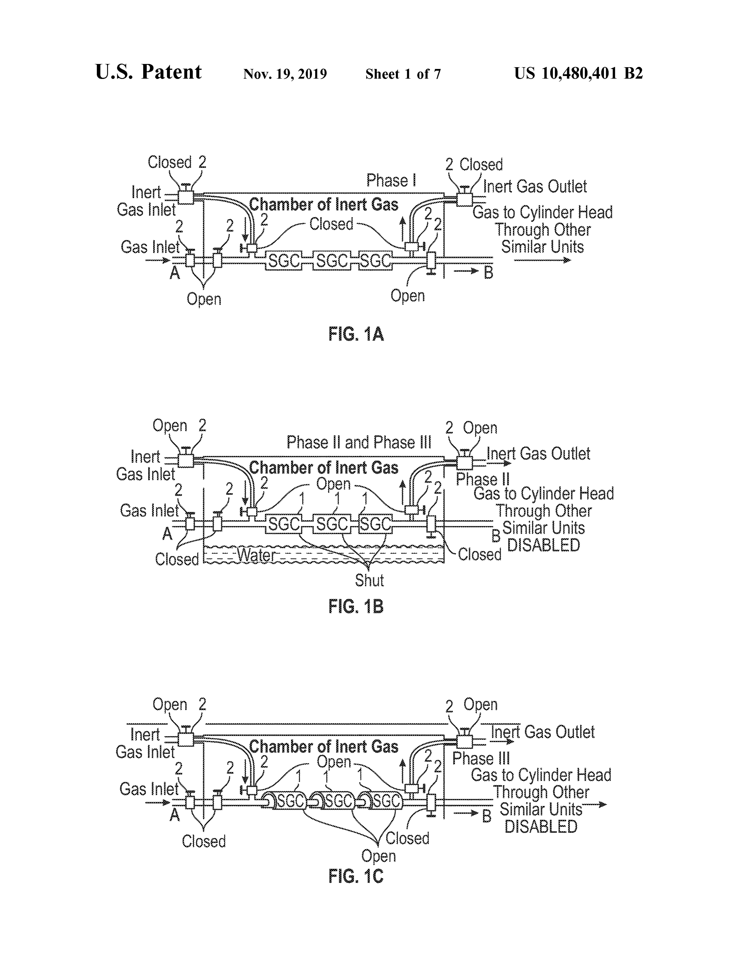
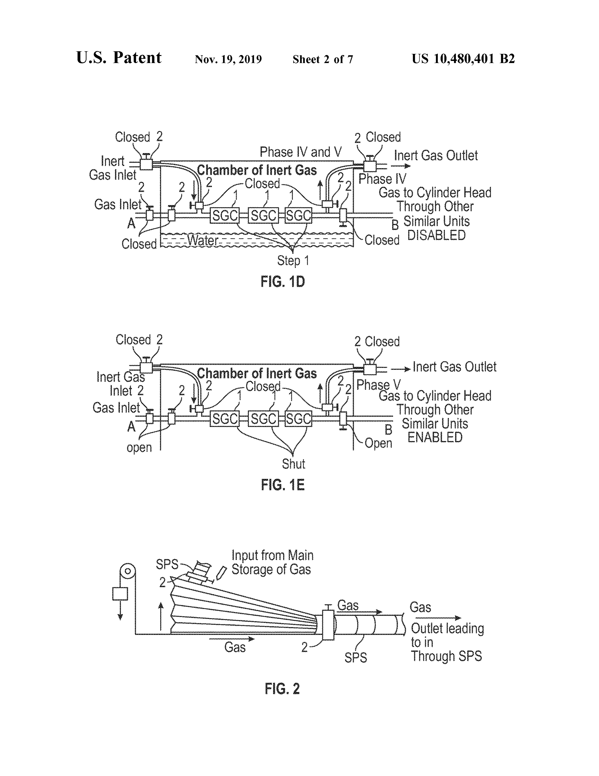
EH1 and CC opens and stay fixed . The explosive power pushes piston ( s) with hydraulic transmission of power and BRIEF DESCRIPTION OF ACCOMPANYING as piston (s ) return to their original position (s) through 30 DRAWINGS mechanicalmeans known in the art; gas enters EH2 to form gas bubble up to its RVG stage and undergo the same The foregoing and further objects, features and advan process as EH went through . Simultaneously and indepen tages of the present subject matter will become apparent dently of the happenings in EH2, water valve opens to fill from the following description of example embodiments EH1 and CC with chilled water; and exhaust valve opens to 35 with reference to the accompanying drawings, wherein like drive all trace of gas inside EH1. Hatch secures EH1 numerals are used to represent like elements and wherein : separating EH1 and CC while the hatch separating EH2 and FIGS. 1 ( A ), 1 (B ), 1 (C ), 1 (D ) & 1 (E ) are schematic CC opens and stay fixed until explosion takes place inside representation of different stages of working of Safe Pipe EH2. All EHS act likewise turn -after -turn to make the piston System (SPS ) or IEEX -SM ( 111 ) SPS , which is Safe Mea and crankshaft assemblies produce torque . 40 sure (SM ) as conceived and tried in real research and The present subjectmatter also describes an engine head experiments. SPS is a key device to run any engine with H2 IEEX - EH (900 ) of a serially operating internal combustion or HHO gas , and is in accordance with an embodimentof the (SOIC ) engine. The engine head is provided with at least one present subject matter.
inlet for water and at least one inlet for fuel gases H2 or HHO FIG . 2 is a schematic representation of working of Inter and O2 respectively . The engine head is also provided with 45 mediate Storage of Gas (ISG ) or IEEX -SM (222 ) ISG , at least one outlet for exhaust gases. There is also provided which is Safe Measure as conceived and tried in real at least one top water level and at least one bottom water research and experiments . It is a key device to run any level sensor for measuring water quantity and , regulating engine with H2 or HHO gas, and is in accordance with an requirement of water in the engine head IEEX -EH (900). embodiment of the present subject matter.
The fuel gases H , or HHO and O2 replaces water in the 50 FIG . 3 is a schematic representation of different stages of engine head IEEX - EH ( 900 ) on command of the top water working of Pre-disposal Treatment of Exhaust (PDTE ) or level sensor ( 102 ) and rise as bubbles to acquire required IEEX - SM (333 ) PDTE which is Safe Measure as conceived volume of gas in an upper part of the engine head IEEX - EH and tried in real research and experiments . It is a key device ( 900 ). The engine head also has at least one sparking to run any engine with H , or HHO gas , and is in accordance assembly for creating explosion inside the engine head . 55 with an embodiment of the present subject matter . The present subject matter further describes an engine FIGS. 4 (A ), 4 (B ) & 4 (C ) are schematic representation head IEEX -EH (901 ) of a serially operating internal com of different stages of working of IEEX - EM SOIC ( 100 ); bustion (SOIC ) engine . The engine head is provided with at SOIC with at least one CC , two pistons and two EHs least one inlet and at least one outlet for salt water ; and at working with substantially pure compressed H2 gas and least one outlet for exhaust gases. There is also provided at 60 substantially pure O2 gas in cold condition or substantially least one top water level and at least one bottom water level purified HHO in cold condition as fuel, and is in accordance sensor for measuring salt water quantity and , regulating with an embodiment of the present subject matter. requirement of salt water in the engine head IEEX -EH (901). FIG . 5 is a schematic representation of different stages of The engine head is further provided with an electrode working of IEEX -EM SOIC (200 ) engine of “ L ” shape with assembly in close proximity. The electrode assembly is 65 one cylinder , one piston and one engine head . IEEX - EM provided for electrolysis of salt water , thereby producing SOIC (200 ) uses substantially pure compressed H2 gas and fuel gases H , or HHO and 0 , in the engine head IEEX -EH substantially pure O2 gas in cold condition or substantially
Page 13
purified HHO in cold condition as fuel , and is in accordance three valves provided for opening and closing of the main with an embodiment of the present subject matter . pipeline and two valves that allow inert gas to enter themain FIG . 6 is a schematic representation ofworking of IEEX pipeline so as to flush out gas and air from the system and EM SOIC (300) engine of“ I” shape with one cylinder, one 5 to escape the main pipeline respectively . However, the piston , one CC and several EHs. IEEX -EM SOIC (300 ) uses configuration described herein is not limited to three SGCs substantially pure compressed H , gas and substantially pure and the respective valves, but can vary in number as would 02 gas in cold condition or substantially purified HHO in be required for any suitable application and in a manner cold condition as fuel, and is in accordance with an embodi appreciated by person skilled in the art. The gas in themain ment of the present subject matter.
FIG . 7 is a schematic representation of working of IEEX- 10 pipeline flows from direction A to B. The chamber allows entry of inert gas which may pass through SGC irrespective
EM SOIC (400) engine of “ O ” shape with several cylinders , of the fact whether SGC is closed or open . several pistons, one CC and several EHs. IEEX -EM SOIC FIGS. 1 (A ), 1 (B ), 1 (C ), 1 (D ) & 1 (E ) illustrates (400) uses substantially pure compressed H2 gas and sub different stages of working of SPS represented in different stantially pure 02 gas in cold condition or substantially purified HHO in cold condition as fuel, and is in accordance is phases from I ofPhase
In Phase FIG .I 1to( AV.); three valves of themain pipeline with an embodiment of the present subject matter.
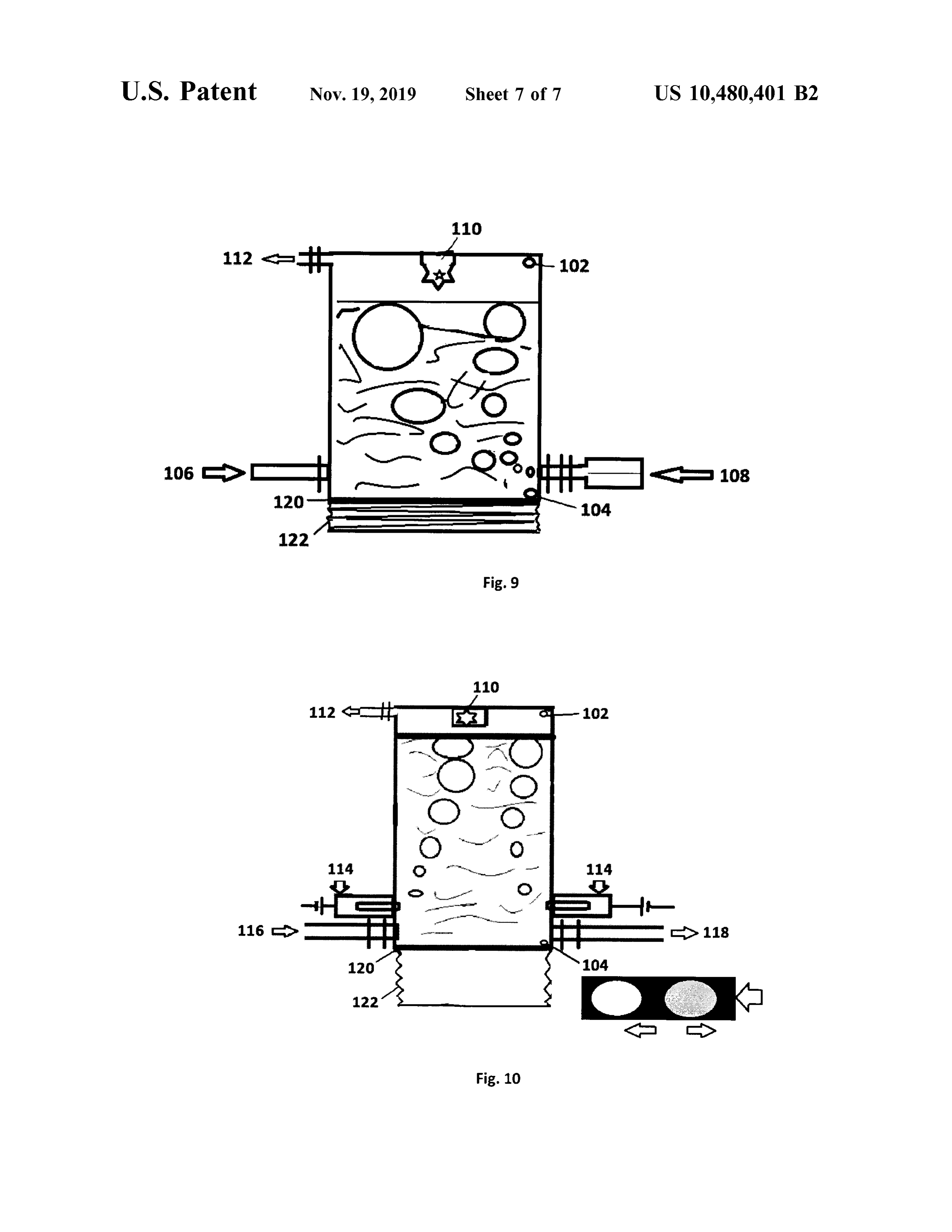
FIG . 8 is a schematic representation of working of IEEX opens up and SGC halves shut tight and all other valves EM SOIC (500 ) engine of any shape with nine cylinders , close. The gas puffs through from ISG to EH without any nine pistons, nine crankshaft assemblies, one CC and several interruption . In Phase II of FIG . 1 ( B ); three valves of the EHs. IEEX - EM SOIC (500) uses substantially pure com- 20 main pipeline are closed and internal valves controlling the pressed H , gas and substantially pure O2 gas in cold con flow of inert gas opens; letting the inert gas flush the dition or substantially purified HHO in cold condition as chamber and the main pipeline inside different segments of fuel, and is in accordance with an embodiment of the present SPS . Phase III in FIG . 1 (C ) operates simultaneously with subject matter. the occurrence of explosion in EH which occurs at the end FIG . 9 is a schematic representation of working of a water 25 of the main pipeline in the direction from A to B. All SGC filled engine head IEEX -EH (900 ) in accordance with an halves open up and inert gas continues to flush the chamber embodiment of the present subject matter. and the parts of the pipe system inside the segments of SPS. FIG . 10 is a schematic representation of working of the In Phase IV of FIG . 1 (D ), SGC halves shut re-forming the engine head filled with salt water and using self- electrolysis main pipeline and the flow of inert gas also shuts down as IEEXpresent
subject accordance . with another embodiment of 30 pipeline the valves letting it flow to the chamber and parts of the main inside segments of SPS are closed . Phase V in FIG .
DETAILED DESCRIPTION 1 ( E ) is identical to Phase I with the difference that the actual flow of gas from ISG to EH awaits a central command . On receiving the command , Phase V is activated and resumes in
The following presents a detailed description of various 35 the embodiments of the present subjectmatter with reference to phases same manner as Phase I; and hence, the subsequent the accompanying drawings. recommence .
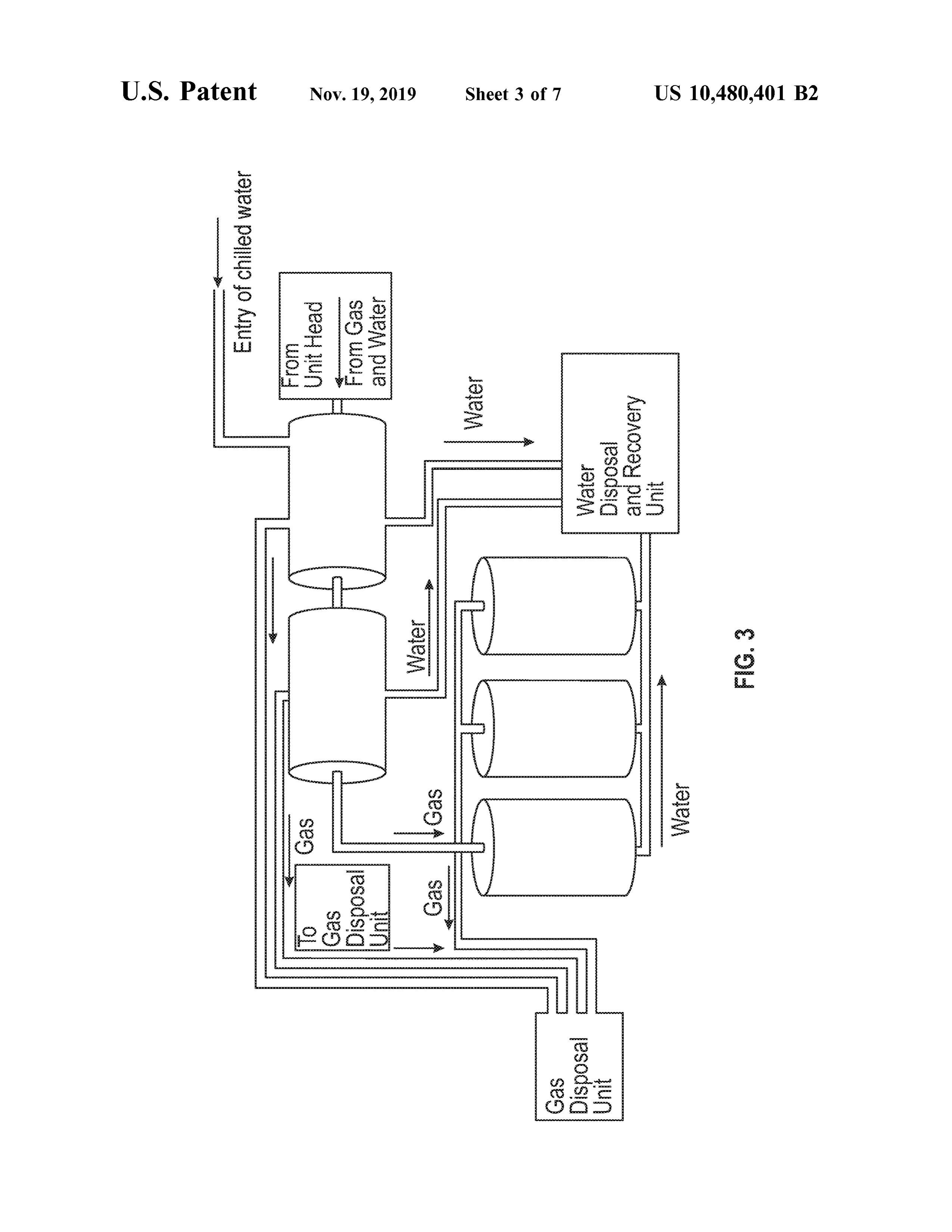
The embodiments of the present subject matter are FIG . 2 illustrates a schematic representation of the work described in detail with reference to the accompanying ing of IEEX -SM ( 222 ) ISG to revolutionize safety from the drawings. However, the present subject matter is not limited 40 hazards that could occur from the backlash of H and HHO to these embodiments, which are only provided to explain gases with the use of a simple , flexible and straightforward more clearly the present subject matter to the ordinarily device . The representation of ISG looks like a bellow skilled in the art of the present disclosure . In the accompa because the concept resembles the working of a bellow . The nying drawings, like reference numerals are used to indicate bellow is made of a flexible material that tears at low like components. 45 pressure reducing the force of an explosion if, and when ; an FIGS . 1 ( A ), 1 (B ), 1 ( C ), 1 (D ) & 1 ( E ) illustrates a safe explosion happens at ISG and that way, the main storage of way of transporting inflammable and explosive gas through gas (MSG ) in the neighbourhood stays unaffected as pipe system called SPS . IEEX -SM (111 ) SPS is safe measure observed during experiments conducted with prototype to revolutionize safety while transporting potentially explo engines. Bellow has limited storage space and expels the sive or volatile or inflammable fluid . SPS benefits all the 50 gaseous content in a fast and abrupt manner. Although the units using, handling, storing and /or transporting such fluids , working principle of ISG resembles that of an ordinary as for example ,but not limited to ; several engines and other bellow , ISG requires assemblage of sophisticated measuring facilities using such fluids, various establishments storing and timing instrumentation known in the art ; so that required and transporting such fluids on several occasions, service volume of gas (RVG ) reaches EH at correct time, precise organisations (mobile and stationary ) handling or selling 55 speed , specific pressure and in exact volume or weight. potentially explosive or inflammable fluids etc. FIGS. 1 (A ), FIG . 3 illustrates a schematic representation of different 1 (B ), 1 (C ), 1 (D ) & 1 (E ) best illustrates SPS for gases and stages of working of IEEX - SM (333 ) PDTE to revolutionise the one for liquids would require modification of the present safety from accidents taking place at the stage of exhaust configuration . FIGS. 1 ( A ), 1 (B ), 1 (C ), 1 (D ) & 1 (E ) release of H , or 02 or HHO gas engines. This seemingly represents SPS in the form of a chamber with three sides 60 unlikely event of accident occurring at this stage is not really firmly closed and the chamber stands over a collection of uncommon and the real experiments showed its propensity ; water in fixed locations but may also use flexible thin alarming the need of stricter security and safety concerns . membrane in movable units . Water and thin membrane on The exhaust unit processing in the form of PDTE ensures the fourth side of the chamber acts as an abundant caution safety from escape of gas and steam at high temperature . against accidental insufficiency in the flow of inert gas, or 65 PDTE cools the steam and unspent gas from the engine head sabotage. The chamber includes a main pipeline having with chilled water and forces the gaseous volumes to gas three SGCs interconnected with pipe segments . There are disposal unit through jet like contrivances and is disposed in
Page 14
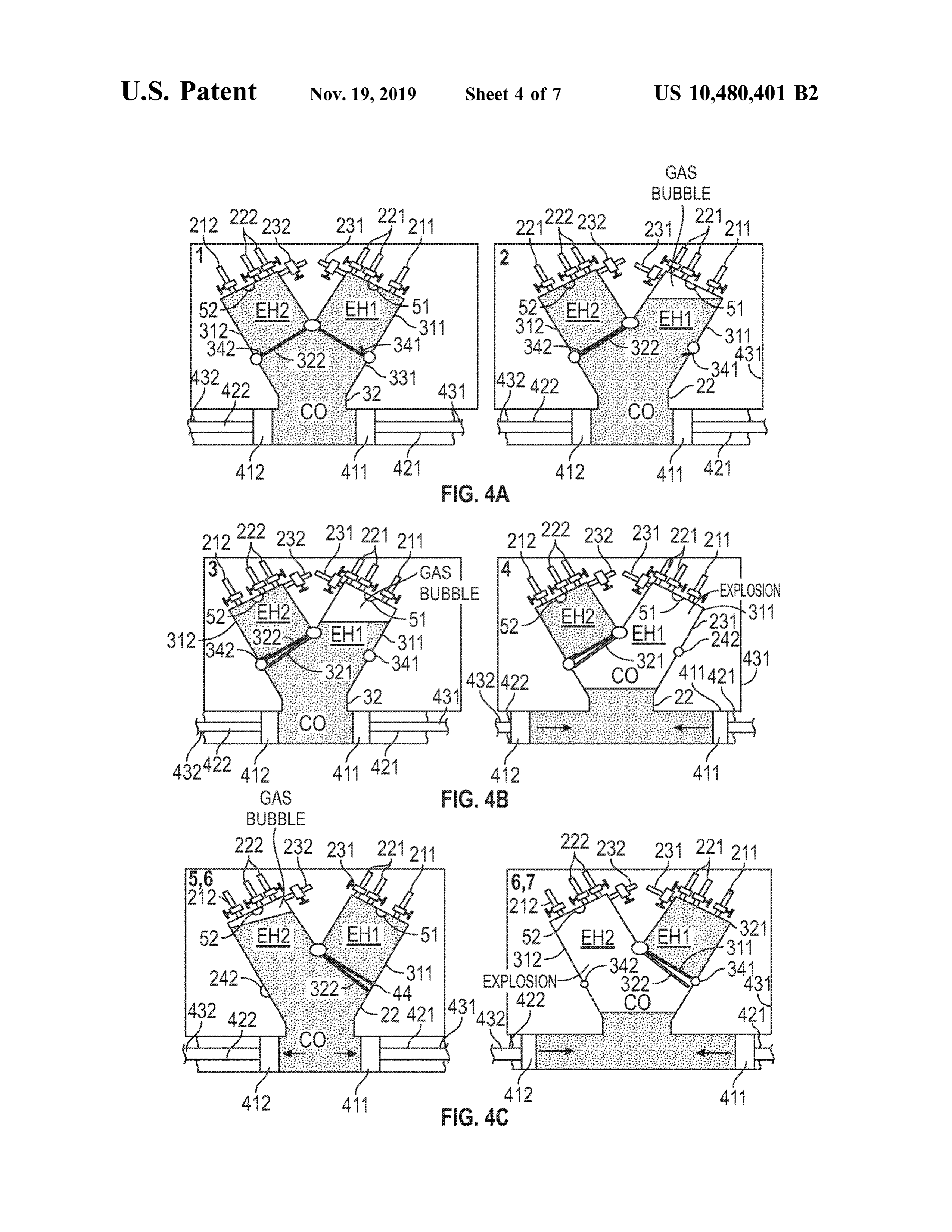
a safe manner as is known in the art whereas, water is fed IEEX -EM SOIC engine ( 100 ) submerged in water and to the water disposal and recovery unit for recycling pur represented graphically in FIGS. 4 ( A ), 4 (B ) & 4 (C ); poses. includes but in no ways limited to ; one cylinder (32 ) filled FIGS. 4 ( A ), 4 (B ) & 4 (C ) illustrates a schematic with water and continuously refilled with chilled water; one representation of different stages of working of IEEX - EM 5 or more pistons (411, 412 ) connected to separate crankshaft SOIC engine (100 ) with one CC (32 ) of inverted “ T ” shape ; assemblies ( 431,432 ); two or more engine heads (900 , 901 ); and CC (32 ) having one vertical and two horizontal arms. and the gas inlet and outlet valves (221, 222 ) and (231 , 232 ) The horizontal armsof CC contain CPS of two pistons (411 , provided to serve each engine head (900 , 901 ) respectively ; 412 ) that moves to and fro to produce torque in the manner 10 further provided with water inlet and outlet assemblies (211 , as known in the art. The vertical arm of CC ( 32 ) bifurcates 212 ); and the hatch separators ( 331 , 332) separating the into , but not limited to EH1 & EH2 ( 900 , 901 ) and can house cylinder (32 ) from engine heads (900 , 901 ) and hatch more than two Ells according to the requirement and securers (341 , 342 ) securing the hatch between cylinder (32 ) acknowledging economical running of engine. The working and engine heads (900 , 901 ); the spark assemblies (51, 52) of IEEX - EM SOIC engine ( 100 ) is described in different 15 inside engine heads (900 , 901 ) and also , the gas bubble stages i.e., from Stage 1-8 . IEEX -EM SOIC engine (100 ) (marked “ Gas Bubble” ) is formed at top of each engine head stays submerged in water that gradually warms up as the (900, 901) alternatively. PDET systems (241,242 ) serve each engine starts working and exothermic properties of the EH separately . The subject matter viz., assemblage of gases reaction taking place manifests . CC ( 32 ) and EHS ( 900 , 901 ) from electrolysis , layout of gas inlet assembly, gas regulator, in the engine (100 ) are continuously refilled with chilled 20 ignition assembly, crankshaft assembly ; and transfer of water. FIG . 4 ( A ) represents EH1 (900 ) as the first EH to linear motion of piston to produce torque ; and so on are start working. In the beginning , all the valves (211 , 212 , 231, configured and carried out in the samemanner as known in 232 & 222 ) remain closed and only the gas inlet valve ( 221) the art.
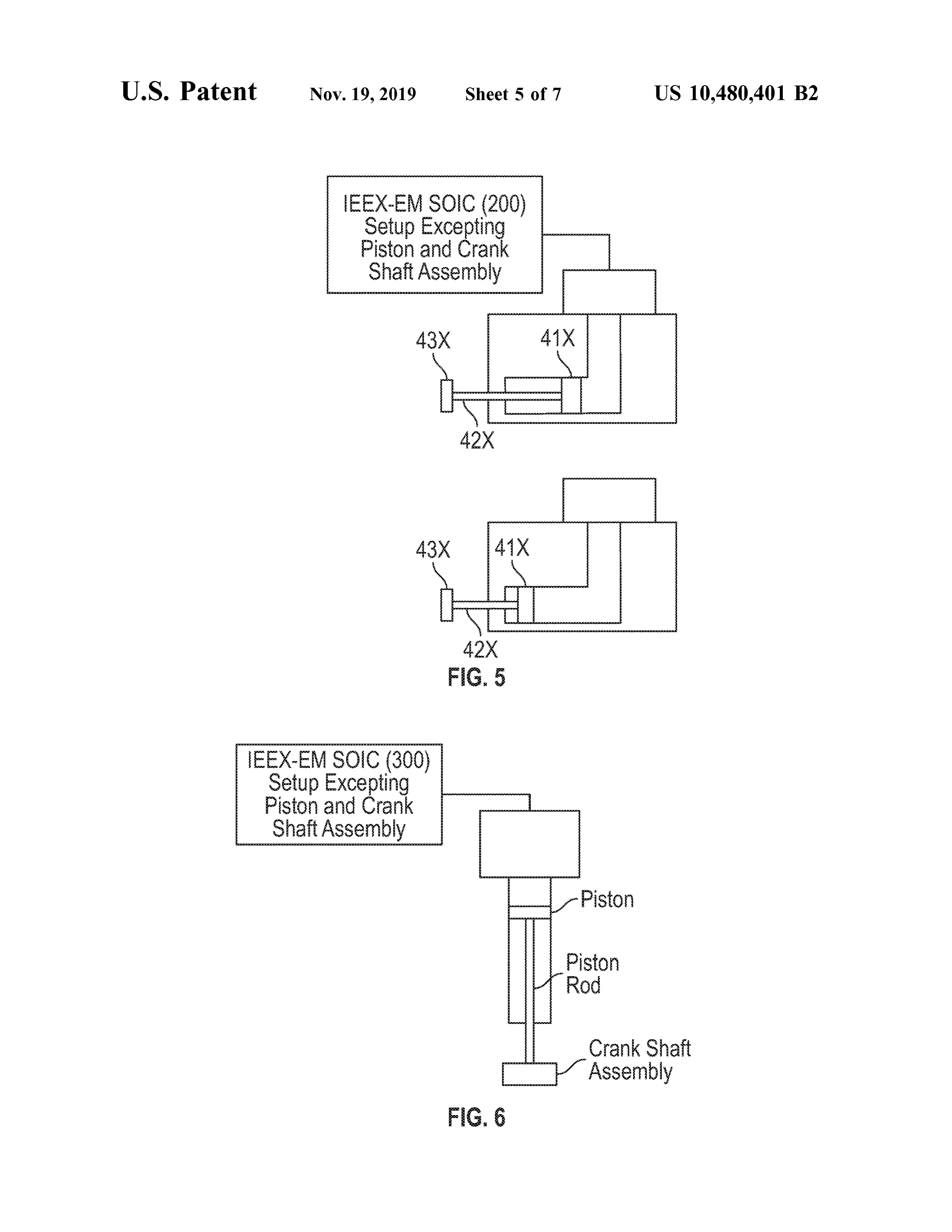
to EH1 (900 ) opens up on command and EH1 (900 ) lets in FIG . 5 illustrates a schematic representation of working of gas forming a bubble inside EH1 (900 ) and the gas inlet 25 IEEX - EM SOIC (200 ) of “ L ” shape , which is same in valve ( 221) remains open until EH1 (900 ) is full of bubble essence as IEEX -EM SOIC ( 100); except only one piston acquiring its RVG level ; opening up the hatch (331 ) between ( 41X ) and crankshaft assembly (43X ) is employed in IEEX EH1 (900 ) and CC (32 ) while the other between EH2 (901 ) EM SOIC (200 ) instead of two as in IEEX -EM SOIC ( 100 ). and CC ( 32 ) stay firmly secured at its position; all the valves IEEX -EM SOIC (200 ) is applicable for all those purposes (211, 212 , 231 , 232 , 221 & 222 ) are firmly closed ; and 30 where engine miniaturisation is required . activating the spark assembly (51) inside EH1 (900 ) which first triggers implosion pulling piston assembly (411, 412 ) IEEX -EM6 illustrates
FIG . a schematic representation of working of
SOIC (300 ) of “ I” shape, which is same in firmly to the position and explosion next inside the chamber (32) pushing the water inside EH1 (900 ) and CC essence as IEEX -EM SOIC (200 ); except shape of the two (32) and displaces pistons (411, 412 ) from the start position 35 those enginespurposes
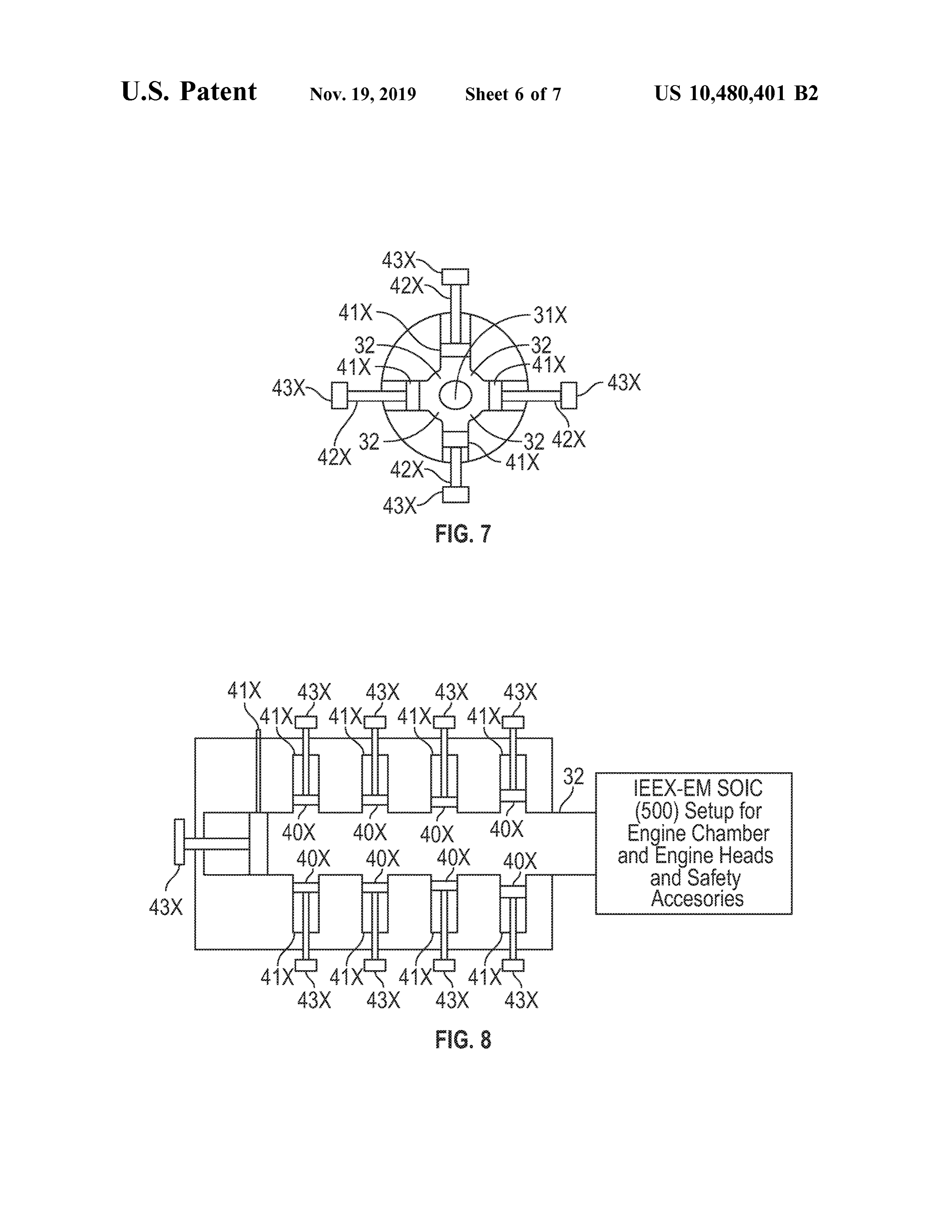
EM SOIC engine(300) is also applicable miniaturisation for .all is required to the end position. The pistons (411 , 412) return to the start FIG . 7 illustrates a schematic representation ofworking of position with mechanical means known in the art and await the second explosion to reach the end position again . In the IEEX - EM SOIC (400) of “ O ” shape , which is same in meanwhile, CC ( 32 ) and EH1 (900) gets refilled with chilled essence as IEEX - EM SOIC (100 ); except IEEX - EM SOIC water, and the unused gas inside EH1 (900 ) eases out and 40 (400) works on four pistons (41X ) and four sets of crank enters the gas disposal unit through PDTE (not shown in the shaft assemblies (43X ) instead of two as in IEEX -EM SOIC fig .) and simultaneously , the same process continues to ( 100 ). Also , the chamber (32) of IEEX -EM SOIC ( 400) is happen in EH2 (901) i.e., gas bubble forms on the top of “ O ” shaped and can accommodate more than four engine EH2 ( 901 ); opening up the hatch ( 332 ) between EH2 (901 ) heads ( 31X ) whereas chamber of IEEX - EM SOIC ( 100 ) is and CC ( 32 ) and activating the spark assembly (52 ) inside 45 “ Y ” shaped and speculatively accommodates four to six EH2 (901 ) that triggers the same implosion first and explo engine heads. IEEX -EM SOIC (400 ) stands applicable for sion next phenomenon inside EH2 (901) and pushes the all those purposes where maximising engine power is water present in EH2 (901) and CC (32 ) that causes the desired .
pistons (411, 412 ) to once again reach to their end positions FIG . 8 illustrates a schematic representation ofworking of and transmit the force of explosion to the respective crank- 50 IEEX - EM SOIC (500 ) having multiple piston assemblies shaft assemblies ( 431 , 432 ). The force of explosion causing (40X ) and crankshaft assemblies (43X ), which is same in the water to exit with high pressure through the end of CC essence as IEEX -EM SOIC ( 100 ), except that the subsidiary (32) can also be used to rotate at least one turbine or throw piston assemblies sideline the main piston assembly . This at least one projectile and produce energy . The same opera concept comes from the possibility that the design of IEEX tion continues in the subsequent engine heads, if there were 55 EM SOIC (100 ) has huge (colossal) proportions and the any, otherwise EH1 (900 ) reactivates . In this way , the serial consolidated power of explosion requires pulling of many operation of IEEX - EM SOIC ( 100 ) engine continues. The mechanical devices such as piston assemblies and crankshaft implosion generated heat and the repeated and continuous assemblies to avoid wastage of power.
movement ofmechanical parts raises temperature ofwater The present subject matter presents an internal combus present within the system . The hot water and the steam thus 60 tion engine (IEEX -EM ) that differs from the internal com produced can be used for various applications including , but bustion engines known in state -of- the art ; in a manner that not limited to the power plants ; where the warm water (IEEX -EM ) of the present subject matter need not stay surrounding SOIC (100 ) enters another large container of dependent upon a crankshaft action to repeat performance of water and heated further to raise temperature ofwater inside the motive force to keep the engine running. The electronics the new container to two to four hundred degree Celsius and 65 and other devices help control the running of the engine. the compressed steam is used for turning steam turbines as Further, (IEEX -EM ) of the present subject matter can known in the art to produce power. produce and supply itself H , based fuel, inject fuel gas as
Page 15
bubbles and adjust volume and pressure of gas injected with The gases on igniting combine at a very high speed and the screwing movement of the engine head ( EH ) that makes the high temperatures inherent to the chemistry of union of ( IEEX - EM ). hydrogen with oxygen causes steam to expand with great According to an embodiment of the present subjectmat rapidity and thus, resulting in a significant explosion . The ter , the working of the engine head IEEX - EH (900 ) is 5 water inside EH is temporarily kept in place by the implo illustrated as shown in FIG . 9. IEEX -EH ( 900 ) is filled with sive property of the union of hydrogen and oxygen that water and the fuel gases H , or HHO and O2 are inducted reduces the gaseous volume to one third level and produces externally into the engine head i.e., using any suitable steam that expands and explodes with the intense exother external means for transporting gases as described in above mic heat of the chemical reaction .
embodiments or means as known in the art. The fuel gases 10 The explosion then causes a great thrust to push water and collect as bubbles in an upper or closed part of the engine air ahead through the lower end of IEEX -EH ( 900 ); which head. The engine head IEEX -EH ( 900) is also provided with is now open and clear of any obstructions. The thrust at least one top water level sensor (102 ) and at least one generated is utilised to activate piston ; rotate turbine or bottom water level sensor ( 104 ) for measuring water quan throw projectile in the manner as described in above tity and, then regulating the requirement of water inside 15 embodiments.
IEEX - EH (900 ). There is also provided a water inlet (106 ), On completion of the event of generation of thrust , the a gas inlet ( 108 ); and an exhaust outlet (112 ) in IEEX - EI-I engine head IEEX -EH (900 ) returns to the initial position (900) as represented in FIG . 9. The engine head IEEX -EH and let the second and subsequent cycles of gas - ignition ( 900 ) also possess at least one sparking assembly ( 110 ) for explosion - thrust take place in the manner as described in ignition of the gaseous fuel. 20 above embodiments .
The concept ofworking of the engine head as hereinafter After the explosion has occurred , the engine head IEEX described explains as to how the flow of water and gas in the EH (900 ) is refilled with water and all the unspent gases are engine head is regulated to have controlled and stable directed towards the exhaust disposal and /or treatment unit transmission of force and explosion inside the engine head . as described in above embodiments. Also , the outlet valve The present subject matter is directed towards the con- 25 ( 112 ) towards the exhaust treatment unit remains open till figuration and functioning of the engine head IEEX -EH the time the top water level sensor ( 102 ) reports “ FULL " ( 900 ); with the engine head IEEX - EH (900 ) as described and , is closed and firmly secured thereafter allowing the hereinbefore and hereinafter enabled to be engaged with the entire inlet and outlet process to continue in the manner serially operating internal combustion (SOIC ) engine as sought after.
explained above in various embodiments . 30 It is in accordance with another embodiment of the The water from the water inlet ( 106 ) flows into the engine present subject matter that the engine head IEEX -EH (901) head IEEX - EH (900 ) and the valve ( 106 ) remains open till makes use of the principle of electrolysis of salt water for the time the top water level sensor (102 ) reports “ FULL ” producing and directly transporting hydrogen gas and oxy i.e., on reading “ FULL ” the water inlet ( 106 ) closes and the gen to the engine head IEEX -EH ( 901) as represented in gas inlet (108 ) opens up to replace the water present in the 35 FIG . 10 and , thus eliminating the need for separate trans engine head IEEX - EH ( 900) by gas. portation system required for transporting gas with the It is in accordance to an embodiment of the present hazards of escaping gas causing explosion unwantedly. subject matter that a tube ( 120 ) of IEEX -EH (900 ) is FIG . 10 is a schematic representation of the working of an directed to rotate or screw or act in any other possible engine head IEEX -EH (901 ) which is a salt water filled manner as can be conceived by a person skilled in the art 40 engine head in accordance with an embodiment of the and , suits the present embodiment of the subjectmatter. The present subject matter. The engine head IEEX -EH (901 ) rotation of the tube (120 ) of IEEX -EH (900 ) helps make derives fuel gasesH2, HHO and O , through self-electrolysis room for the rising bubbles to deliver a required volume of as assisted and initiated by an electrode assembly ( 114 ) fuel gases at the upper part of the engine head IEEX -EH placed in or in close proximity of IEEX -EH (901 ). The ( 900 ). Also , a lower end of the tube ( 120 ) of IEEX -EH (900) 45 engine head IEEX -EH (901) is provided with an inlet for salt stays temporarily closed with a sliding device ( 122 ) or any water ( 116 ), an outlet for salt water ( 118 ); and an outlet ( 112 ) other suitable device known in the art in order to obstruct the for exhaust. The engine head IEEX -EH (901 ) is further outflow ofwater from the engine head IEEX -EH (900 ) i.e., provided with at least one top water level sensor ( 102 ) and to hold the water against gravity such that water content in at least one bottom water level sensor ( 104 ) for measuring IEEX - EH (900 ) remains unaltered while the fuel gases rise 50 salt water quantity and , then regulating the requirement of as bubbles . salt water inside IEEX - EH (901); and also possess at least On receiving the required volume of fuel gases in the one sparking assembly ( 110 ).
upper part of IEEX - EH (900), the rotation of the tube ( 120 ) In one embodiment of the present subject matter, the of IEEX -EH ( 900 ) and the obstruction posed at the lower electrode assembly (114 ) is placed on sides of the engine end of the tube (120 ) as explained above comes to a halt so 55 head IEEX -EH ( 901 ). However , the location of the electrode that the gases ignite with the sparking assembly (110 ). assembly (114 ) is subjected to variations and can best be Prior to ignition of the fuel gases all valves (106 , 108 , chosen as per the requirement of the system . An electrical 112 ) connecting to the openings to the engine head IEEX potential is applied across a pair of electrodes immersed in EH (900 ) close except for the lower end of IEEX - EH (900 ). the electrolyte i.e., salt water and the salt water on elec The lower end opposite to the closed end of IEEX -EH (900) 60 trolysis decomposes into oxygen (02) and hydrogen (H2) which had temporarily remain blocked to obstruct the out gas .
flow of water from IEEX - EH ( 900 ) until the ignition takes The engine head IEEX - EH (901); similar to the engine place ; receives a command in synchronicity with the ignition head IEEX -EH (900) let the bubbles of fuel gases that are that sets the lower end of IEEX - EH ( 900) to open . The derived from the electrolysis of salt water to collect in the phenomenon of the closing of valves ( 106 , 108 , 112 ) takes 65 upper part of the engine head . A tube ( 120 ) of IEEX - EH place on the bottom water level sensor (104 ) reporting “ NO (901) is then directed to rotate or screw or act in any other WATER ” . possible manner as can be conceived by a person skilled in
Page 16
the art and , suits the present embodiment of the subject I claim :
matter. The rotation of the tube ( 120 ) of IEEX -EH (901 ) 1. An implosion enabled engine of exothermic type in helps make room for the rising bubbles to deliver a required explosive system (IEEX - EM ) operating as serially operating volume of fuel gases at the upper part of the engine head internal combustion (SOIC ) engine , the IEEX -EM compris IEEX - EH (901 ). Also , the lower end of the tube ( 120 ) of 5 ing at least one cylinder filled with water ; IEEX - EH (901) stays temporarily closed with sliding device one or more piston assemblies connected to one or more (122 ) or any other suitable device known in the art in order crankshaft assemblies to produce torque ; to obstruct the outflow of salt water from the engine head at least one outlet for exhaust of water under pressure to IEEX - EH (901 ) such that salt water content in IEEX - EH rotate at least one turbine or throw at least one projec ( 901 ) remains unaltered while the fuel gases rise as bubbles . 10 tile using the power of explosion ; On receiving the required volume of fuel gases in the one or more engine heads filled with water; upper part of IEEX - EH (901), the rotation of the tube of at least one gas inlet and one gas outlet valve for said each IEEX -EH (901) and the obstruction posed at the lower end engine head;
of the tube as explained above comes to a halt so that the at least one hatch separator for separating said at least one gases ignite with the sparking assembly (110 ). 15 cylinder — from said each engine head; and
Prior to ignition of the fuel gases; all valves (116 , 118 , 112 ) connecting to the openings to the engine head IEEX at least one sparking assembly to ignite mixture of fuel EH ( 901 ) close; except for the lower end of IEEX -EH (901 ). and air in said each engine head . The lower end opposite to the closed end of IEEX -EH ( 901) 2. The implosion enabled engine of exothermic type in which had temporarily remain blocked to obstruct the out- 20 explosive system (IEEXEM ) as claimed in claim 1, wherein flow of salt water from IEEX - EH (901 ) by gravity until the said at least one cylinder and said one or more engineheads ignition takes place ; receives a command in synchronicity are continuously refilled with chilled water . with the ignition that sets the lower end of IEEX - EH (901 ) 3. The implosion enabled engine of exothermic type in to open . The salt water inside EH is temporarily kept in place explosive system (IEEXEM ) as claimed in claim 1 , wherein by the implosive property of the union of hydrogen and 25 at least two pistons are connected to at least two crank oxygen that reduces the gaseous volume to one third level shafts — by at least two piston rods respectively . and produces steam that expands and explodes with the 4. The implosion enabled engine of exothermic type in intense exothermic heat of the chemical reaction . explosive system (IEEXEM ) as claimed in claim 1 , wherein The phenomenon of the closing of valves ( 116 , 118 ) takes place on the bottom water level sensor (104 ) reporting “ NO 30 said one serially operating internal combustion (SOIC ) engine is selected from group consisting of “ Y ” shaped , L ”
WATER ” . shaped , “ I” shaped , “ O ” shaped . The explosion then causes a great thrust to push water and air ahead through the lower end of IEEX -EH ( 901 ); which explosive implosion
system ( enabled engine of exothermic type in
IEEXEM ) as claimed in claim 1, com is now open and clear of any obstructions. The thrust prising two engine heads filled with water. generated is utilised to activate piston ; rotate turbine or 35 6. The implosion enabled engine of exothermic type in throw projectile in the manner as described in above explosive system (IEEXEM ) as claimed in claim 1, com embodiments .
On completion of the event of generation of thrust, the prising one or more water inlet and outlet valves. 7. The implosion enabled engine of exothermic type in engine head IEEX - EH ( 901 ) returns to the initial position explosive system (IEEX -EM ) as claimed in claim 1 , com and let the second and subsequent cycles of gas -ignition- 40 prising at least explosion -thrust take place in the manner as described in said at least oneonecylinder hatch securer for securing hatch between and said each engine head .
above embodiments .
After the explosion has occurred , the engine head IEEX explosive system (IEEXEM ) engine 8. The implosion enabled
of exothermic type in claimed in any one of the
EH (901) is refilled with salt water and all the unspent gases are directed towards the exhaust disposal and /or treatment 45 preceding claims , wherein said one or more engine heads on receiving the required unit as described in above embodiments. Also , the outlet volume of gas (RVG ) forms a bubble of explodable gas valve (112 ) towards the exhaust treatment unit remains open in the upper part; and on receipt of specific command, till the time the top water level sensor ( 102 ) reports “ FULL ” said at least one sparking assembly activates to create and , is closed and firmly secured thereafter allowing the implosion first and explosion next inside the bubble entire inlet and outlet process to continue in the manner 50 causing said at least one hatch securer securing hatch sought after. between said at least one cylinder and said each engine It is to be understood that the above described embodiments are merely illustrative principles of the present subject head to open and stay fixed and explosive power matter and that many variations may be devised by those pushing said one ormore piston assemblies transferring skilled in the art without departing from the scope of the 55 the force of explosion to said one or more crankshaft present subject matter. It is, therefore, intended that such assemblies to produce torque . variations be included with the scope of the claims.
Provenance
- Collection
- Patents citing this work
- Pages
- 16
- Method
- pdftotext (the PDF's own text layer) + pdftoppm 300dpi page scans
- Patent office record
- patents.google.com →
- Source
- Google Patents citing-documents table
- Assignee
- Jitendra Kumar BARTHAKUR
- Inventors
- Jitendra Kumar BARTHAKUR
- Published
- 2019-11-19
- Transcribed from
- patentimages.storage.googleapis.com →