patent · EP0086439B1
Hydrogen Gas Injection System for Internal Combustion Engine
31 January 1990
Page 1 — bibliographic record
Uv) European Patent Office (il) Publication number: 0 086 439
Office européen des brevets B1
EUROPEAN PATENT SPECIFICATION
@®) Date of publication of patent specification: 31.01.90 @ int.ci®: F 02 M 25/12
@ Application number: 83101168.9
Date of filing: 08.02.83
® Hydrogen gas injector system for internal combustion engine.
Priority: 17.02.82 US 349185 @®) Proprietor: Meyer, Stanley A. 3792 Broadway
ae ae Grove City Ohio 43123 (US) ® Date of publication of application:
@ Inventor: Meyer, Stanley A.
3792 Broadwa @) Publication of the grant of the patent: Grove City Ohi 43123 (US)
Representative: Wasmeier, Alfons, Dipl.-Ing.
@) Designated Contracting States: et al
AT BE CH DE FR GBIT LILU NLSE Postfach 382 Greflingerstrasse 7 D-8400 Regensburg (DE) 8) References cited:
Note: Within nine months from the publication of the mention of the grant of the European patent, any person may give notice to the European Patent Office of opposition to the European patent granted. Notice of opposition shall be filed in a written reasoned statement. It shall not be deemed to have been filed until the opposition fee has been paid. (Art. 99(1) European patent convention).
Courier Press, Leamington Spa, England.
Page 2
Description
Cross references and background
There is already proposed for a hydrogen generator a generating system converting water into hydrogen and oxygen gases. In that system and method the hydrogen atoms are dissociated from a water molecule by the application of a non-regulated, non-filtered, low-power, direct current voltage electrical potential applied to two non-oxidizing similar metal plates having water passing therebetween.
Furthermore, there is proposed a hydrogen air processor in which non-combustible gases are controlled in a mixing stage with combustible gas. The hydrogen air processor system utilizes a rotational mechanical gas displacement system to transfer, meter, mix and pressurize the various gases. In the gas transformation process, ambient air is passed through an open flame gas burner system to eliminate gases and other present substances. Thereafter, the non-combustible gas mixture is cooled, filtered for impurity removal, and mechanically mixed with a predetermined amount of hydrogen gas. There results a new synthetic gas. The synthetic gas formation stage also meters and determines the proper gas mixing ratio for establishing the desired burn rate of hydrogen gas. The rotational mechanical gas displacement system in that process determines the volume-amount of synthetic gas to be produced.
The above-noted hydrogen air processor is a multi-stage system having utility in special applications.
Finally, there is proposed a combustion system having utility in a mechanical drive system. Particularly in one instance to drive a piston in an automotive device. There is shown a hydrogen generator for developing hydrogen gas, and perhaps other non-combustible gase such as oxygen and nitrogen. The hydrogen gas with the attendant non-combustible gases are fed via a line to a ccontrolled air intake system. The combined hydrogen, non-combustible gases, and the air after inter mixing are fed to a combustion chamber where it is ignited. The exhaust gases of the combustion chamber are returned in a closed ijoop arrangement to the mixing chamber for the mixture of combustible and non-combustible gases.
From US-Patent 39 82 878 it is known to add to a mixture of hydrogen and oxygen or air a diluent gas, such as carbon dioxide or argon before the mixture is fed into a hydrogen fuel combustor. This patent has the object to provide a method of burning hydrogen at a controlled and relatively low burning rate in the combustor.
US-Patent 39 48 224 refers to a heavier and liquid fuel which has no shortage (heavier than natural gas), no matter what material had been in mind. The average expert hardly will be in a position to derive from this citation that he can operate one and the same system with leaded fuel or unleaded or compressed natural gas or
liquified natural gas. or any other liquid fuel, which is heavier than natural gas, but is available without shortage. Therefore, this teaching cannot assist the average expert.
From DE-A 26 41 228 a hydrogen gas engine systems for vehicles is known, which uses a water disintegrating device for generating hydrogen and oxygen, combining both to oxy-hydrogen gas, which is supplied to the cylinders of the engine, and uses distilled water with 10% sulfuric acid for generating hydrogen and oxygen by electrolysis.
Summary of the invention
The system of the present invention is for a combustion system utilizing hydrogen gas; particularly to drive a piston in an automobile device. The system utilizes a hydrogen generator for developing hydrogen gas. The hydrogen gas and other non-combustible gases are fed to a mixing chamber also having oxygen fed thereto. The mixture is controlled to regulate the burning temperature; that is, to lower the temperature velocity of the hydrogen gas to that of the commercial fuels. The hydrogen gas feed line to the combustion chamber includes a fine linear control gas flow valve. An air intake is the source of oxygen and it also includes a variable valve. The exhaust gases from the combustion chamber are utilized in a controlled manner as the non-combustible gases.
The hydrogen generator is improved upon to include a holding tank to provide a source of startup fuel. Also, the hydrogen gas generator includes a switch to the power source operable from one position to another dependent upon a pressure sensing switch on the combustion chamber.
The simplified structure includes a series of one-way valves, safety valves, and quenching apparatus. The combination of apparatus comprises the complete assembly for converting the standard automobile engine from gasoline (or other fuels) to the hydrogen gas mixture.
Objects
itis accordingly a principal object of the present invention to provide a combustion system of gases combined from a source of hydrogen and non-combustible gases.
Another object of the invention is to provide such a combustion system that intermixes the hydrogen and non-combustible gases in a controlled manner and thereby control the combustion termperature.
Still other objects and features of the present invention will become apparent from the following detailed description when taken in conjunction with the drawings in which:
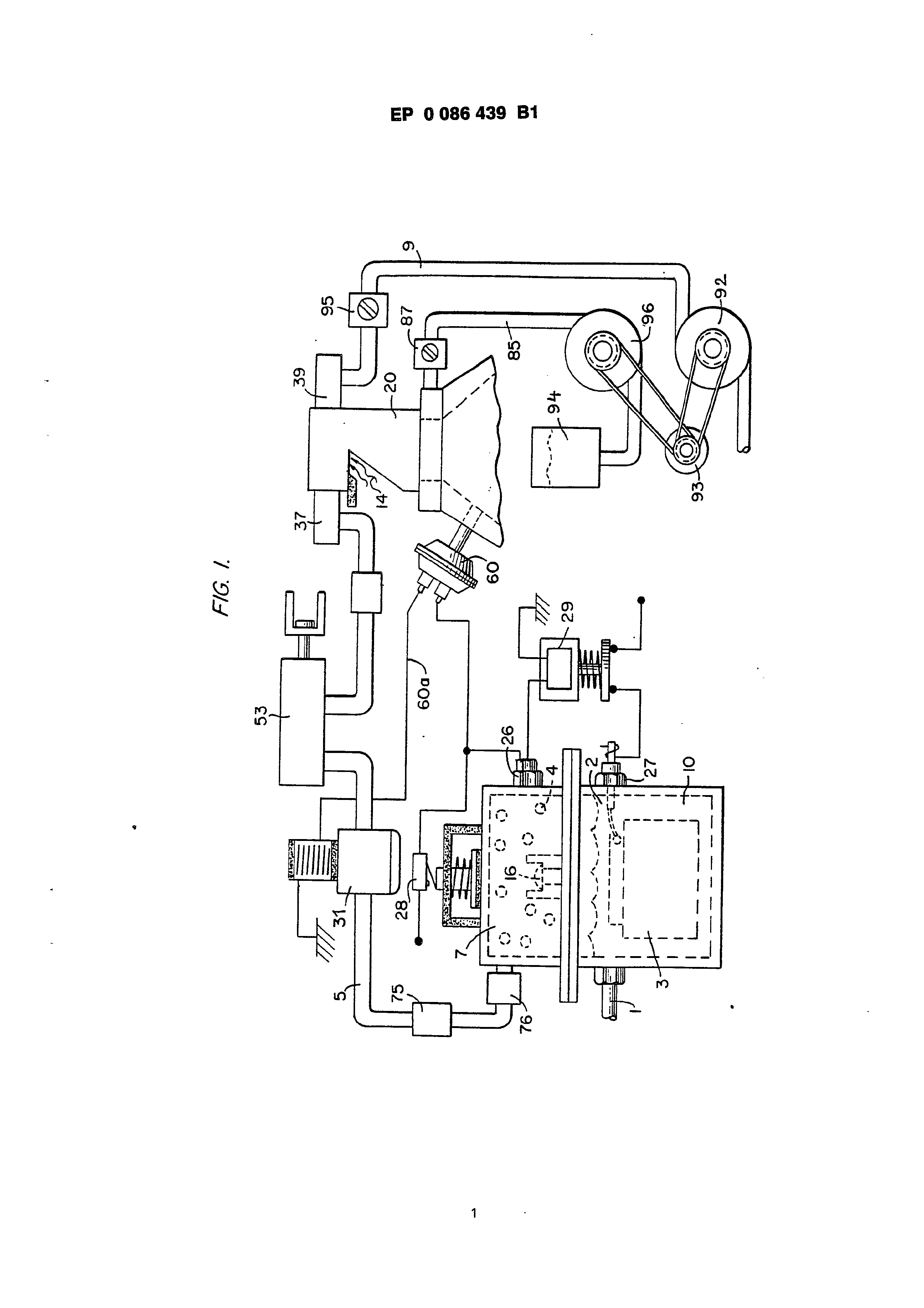
Fig. 1 is a mechanical schematic illustration partly in block form of the present invention;
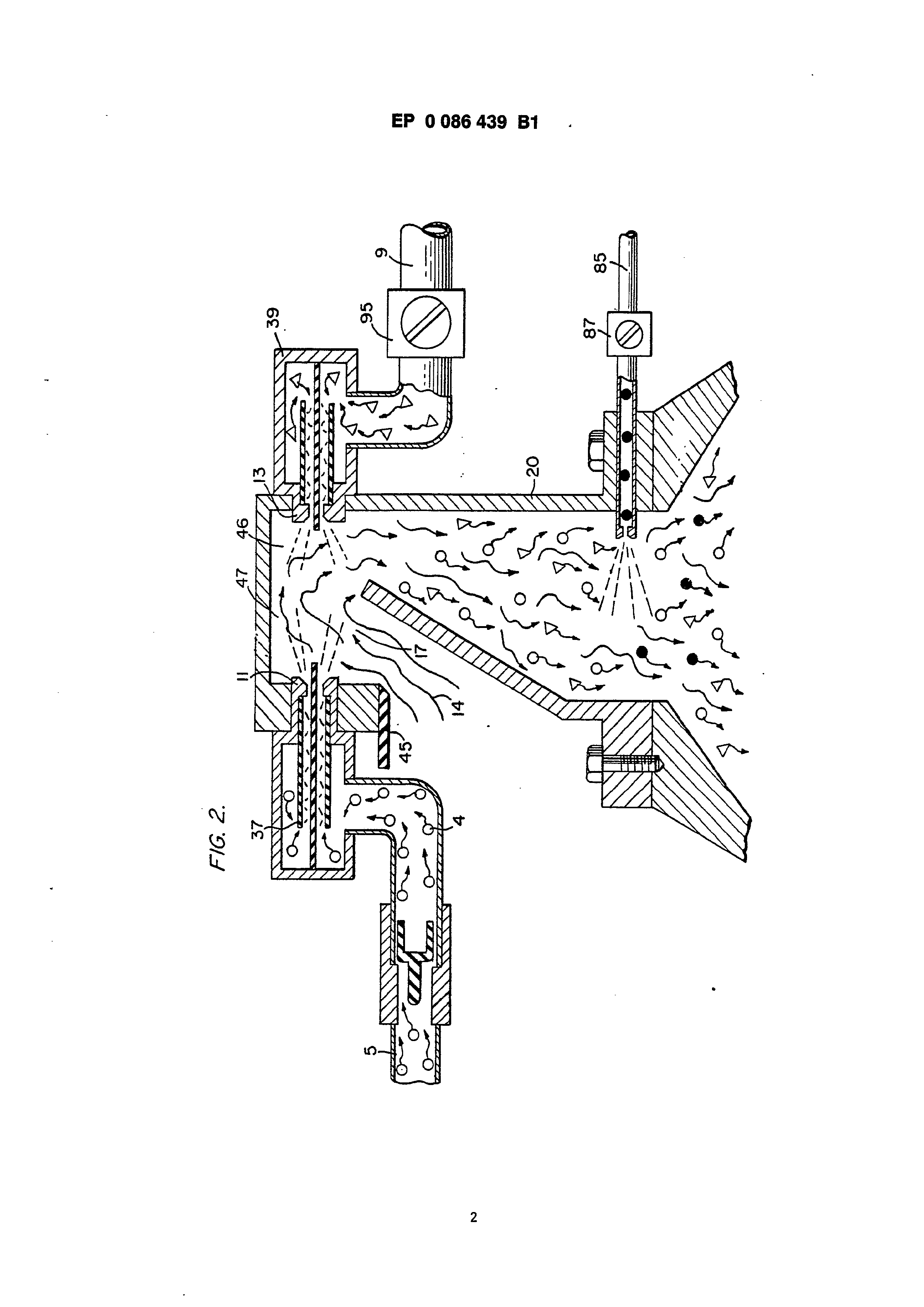
Fig. 2 is a block schematic illustration of the hydrogen injector system of Fig. 1;
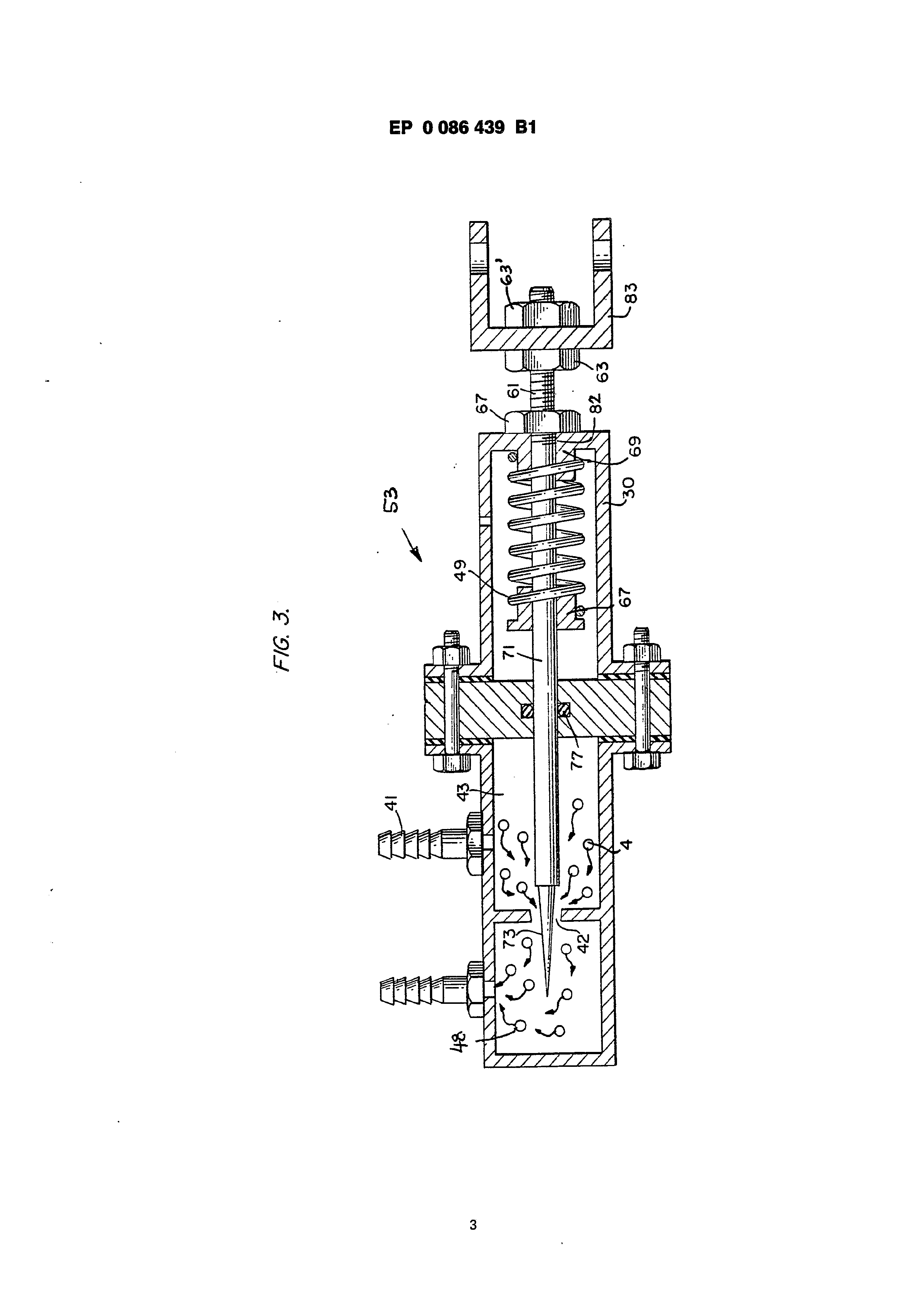
Fig. 3 is the fine linear fuel flow control shown in Fig. 1;
Page 3
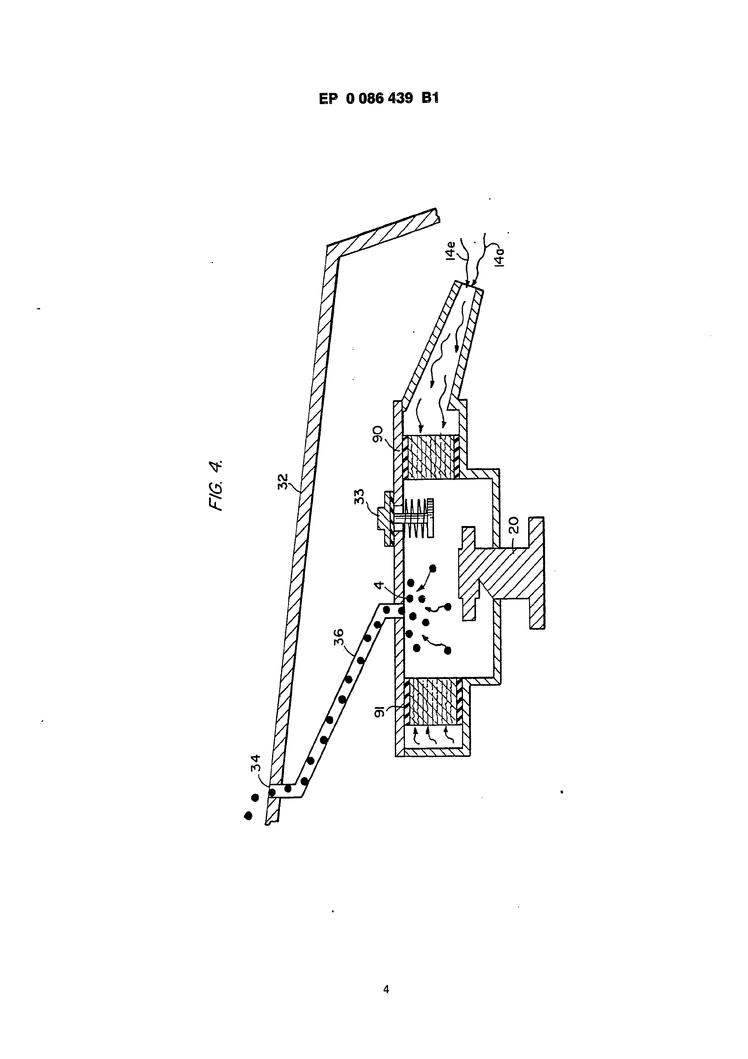
Fig. 4 is a cross-sectional illustration of the complete fuel injector system in an automobile utilizing the concepts of the present invention;
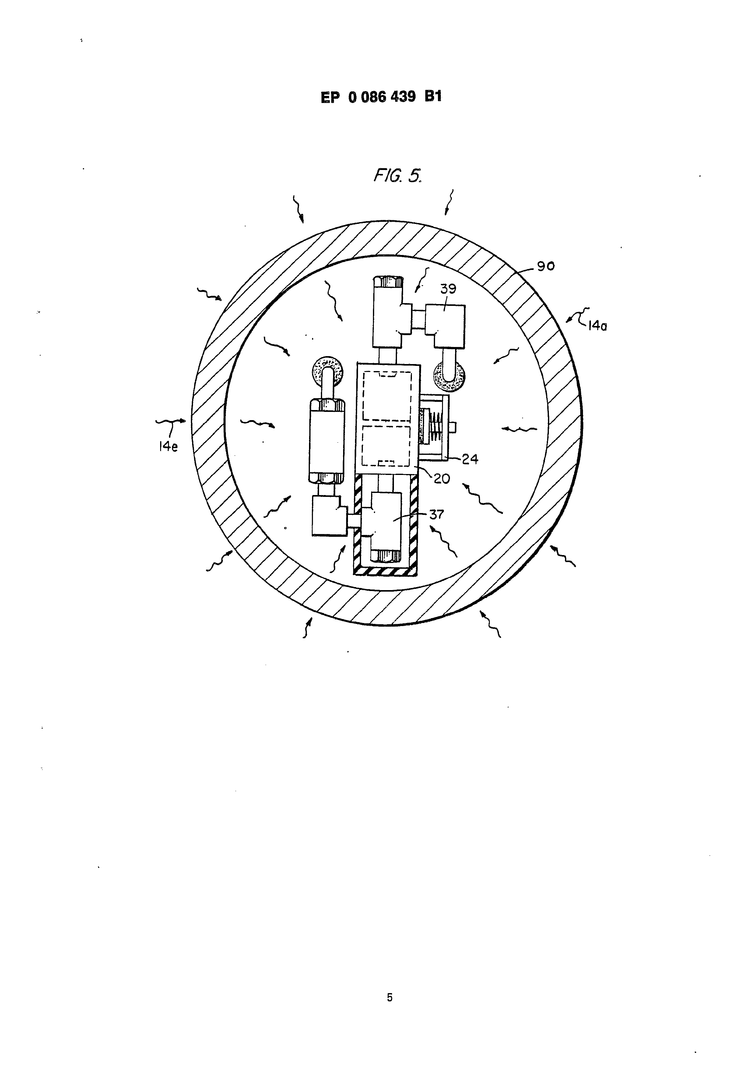
Fig. 5 is a schematic drawing in a top view of the fuel injector system utilized in the invention;
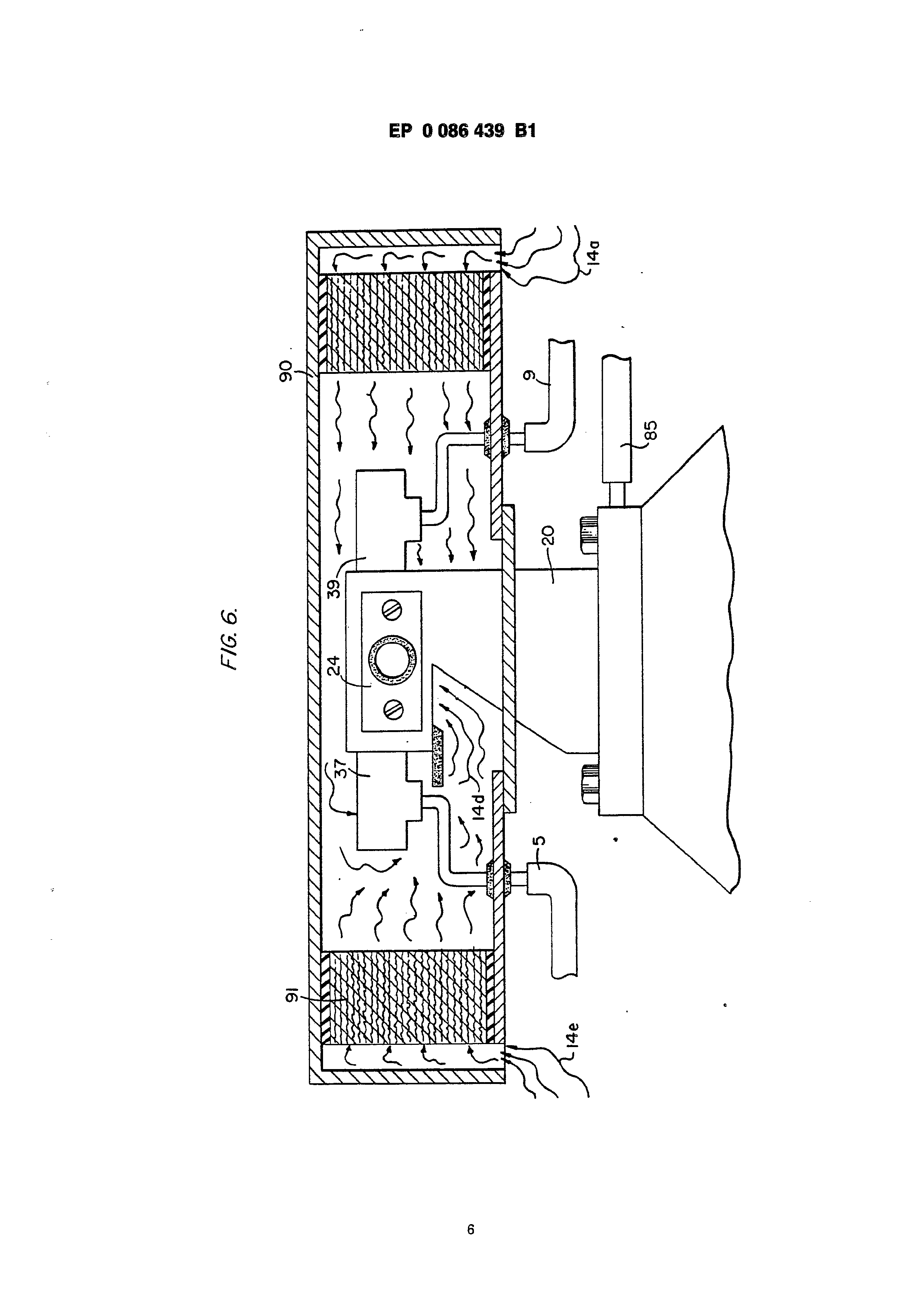
Fig. 6 is a cross-sectional side view of the fuel injector system in the present invention;
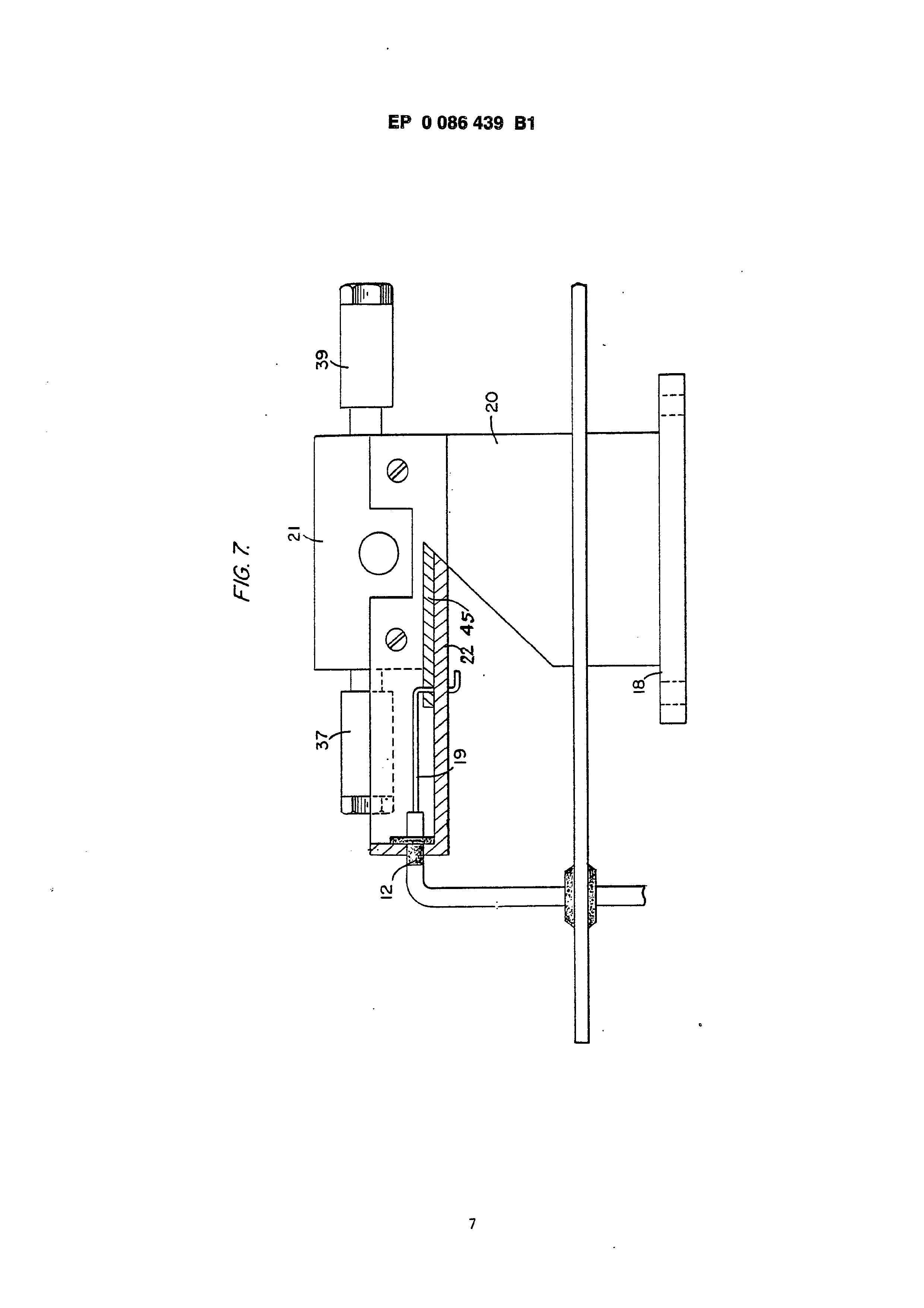
Fig. 7 is a side view of the fuel mixing chamber;
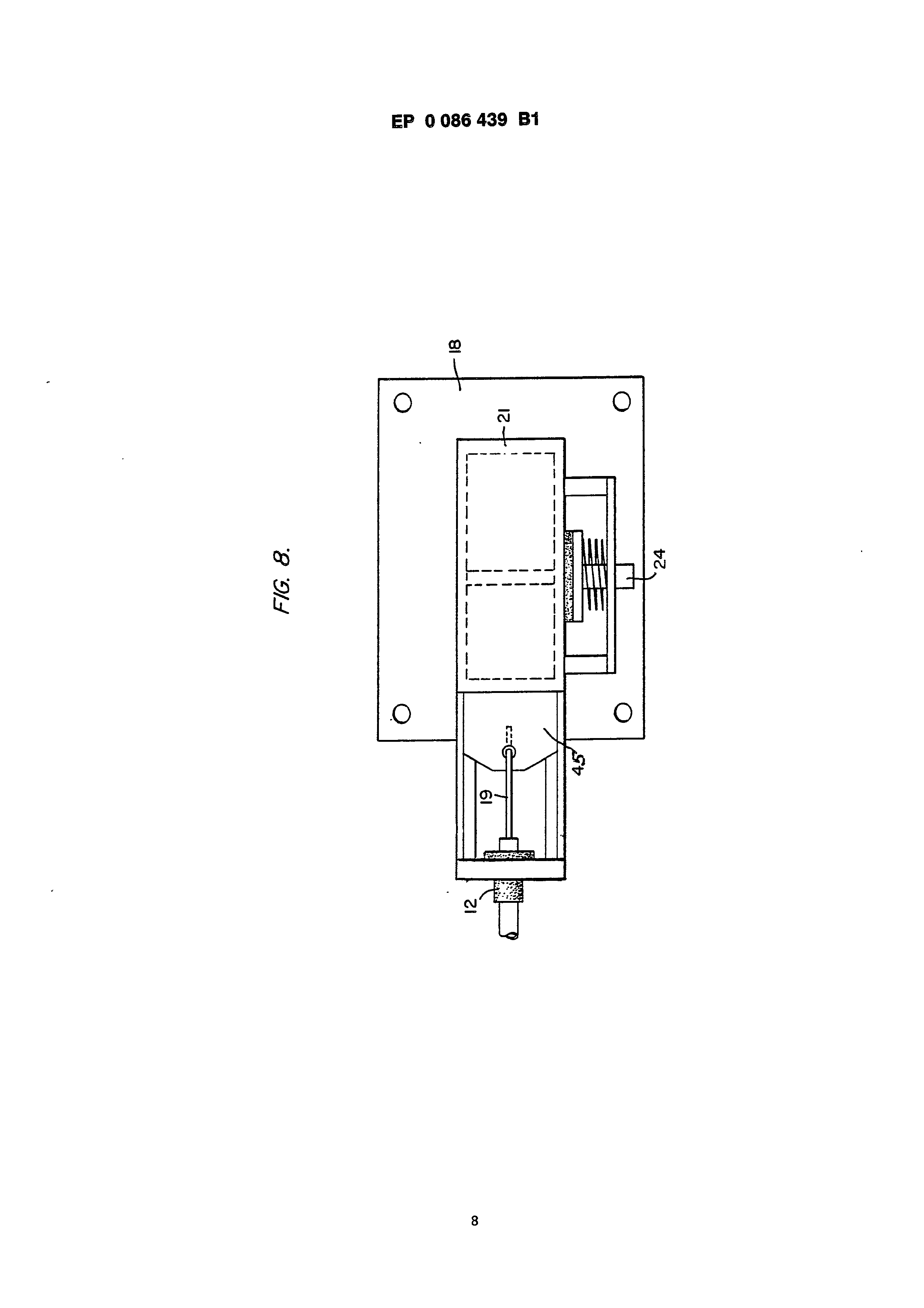
Fig. 8 is a top view of the air intake valve to fuel mixing chamber;
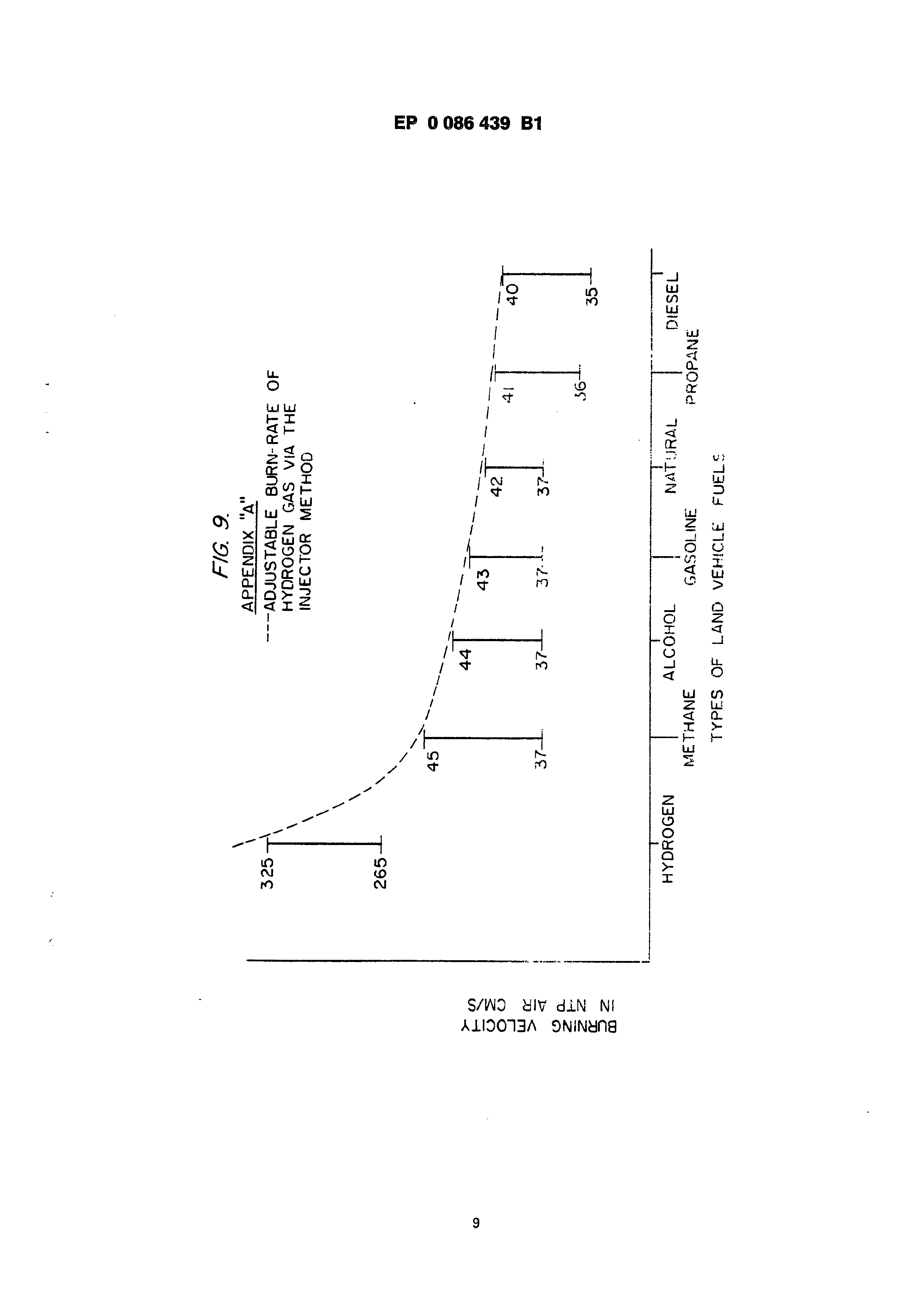
Fig. 9 is a comparison of the burning velocity of hydrogen with respect to other fuels.
Detailed description of invention taken with drawings
Referring to Fig. 1 the complete overall gas mixing and fuel flow system is illustrated together for utilization in a combustion engine particularly an engine utilized in an automobile.
With specific reference to Fig. 1, the hydrogen source 10 is a hydrogen generator. The container 10 is an enclosure for a water bath 2. Immersed in the water 2 is an array of plates 3. Applied to plates 3 is a source of direct current potential via electrical inlet 27. The upper portion 7 of the container 10 is a hydrogen storage area maintaining a predetermined amount of pressure. In this way for start up there will be an immediate flow of hydron gas. To replenish the expended water the generator provides a continuous water source 1.
The safety valve 28 is rupturable upon excessive gas buildup. Whereas the switch 26 is a gas pressure switch to maintain a predetermined gas pressure level about a regulated low volume.
The generated hydrogen gas 4 is fed from the one-way check valve 16 via pipe 5 to a gas mixing chamber 20, wherein the hydrogen gas is intermixed with non-combustible gases supplied via pipe line 9 from a source hereinafter described.
in case one way valve 75 should fail and there is a return spark that might ignite the hydrogen gas 4 in the storage area 7 of hydrogen generator 10, quenching assembly 76 will quench the spark and prevent such ignition.
With particular reference to Fig. 2 the hydrogen gas via pipe line 5 and non-combustible gases via pipe line 9 are fed to a carburator {air-mixture) system 20 also having an ambient air intake 14.
The hydrogen gas 4 is fed via line 5 through nozzle 11 in a spray 17 in to the trap area 47 of the mixing chamber 20. Nozzle 11 has an opening smaller than the plate openings in the quenching assembly 37, thereby preventing flash back in the event of sparking. The non-combustible gases are injected into the mixing chamber 20 trap area 47 in a jet spray 46 via the nozzle 13. Quenching assembly 39 is operable much in the same manner as quenching assembly 37.
The ambient air is the source of oxygen necessary for the combustion of the hydrogen gas. Further, the non-combustible gas are the exhaust gases in a closed loop system.
With continued reference to Fig. 2 the gas trap area 47 is a predetermined size. In that hydrogen is lighter than air, the hydrogen will rise and
become entrapped in the area 47. The size of area 47 is sufficient to contain enough hydrogen gas for instant ignition upon start up of the combustion engine.
It will be noted that the hydrogen gas is injected in the uppermost region of the trap area 47. Hydrogen rises at a much greater velocity than oxygen or non-combustible gases; perphaps three times or greater. Therefore, if the hydrogen gas entered the trap area 47 (mixing area) at its lowermost region the hydrogen gas would rise so rapidly that the air could not mix with the oxygen. With the structure shown in Fig. 2 of the trap area 47, the hydrogen gas is forced downwardly into the upwardly forced air and readily mixed therewith. :
The ratio of the ambient air (oxygen) 14 and the non-combustible gas supplied via line 9 is a controlled ratio and determined by the particular engine. Once the proper combustion rate is determined by the adjustment of valve 95 for varying the amount of the non-combustible gas and the adjustment of valve 45 for varying the amount of the ambient air, the ratio is maintained.
In a system wherein the non-combustible gases are the exhaust gases of an engine in a closed joop-arrangement, and wherein the air intake is under the control! of the engine, the flow velocity and hence the air/non-combustible mixture, is maintained by the acceleration of the engine.
The mixture of air with non-combustible gases becomes the carrier for the hydrogen gas. Thatis, the hydrogen gas is superimposed on the air/noncombustible mixture. By varying the amount of hydrogen gas superimposed on the air/non-combustible mixture, the r.p.m. of an engine can be controlled.
Reference is made to Fig. 3 illustrating precisely in a side view cross section the fine linear fuel flow control 53. The hydrogen gas 4 enters chamber 43 via gas inlet 41. The hydrogen gas passes from chamber 43 to chamber 48 via port opening 42. The amount of gas passing from chamber 43 to chamber 48 is controlled by controlling the port opening 42. ;
The port opening is controlled by the linearly tapered pin 73. The blunt end of pin 73 is part of rod 71. Rad 71 is passed by supporting O-ring 77, through opening 82 is housing 30, to manual adjustment mechanism 83.
The spring 49 retains the rod 71 with the pin 73 in a guided position relative to opening 42. Upon actuating the mechanism 83, the pin 73 will recede from the opening 42 thereby increasing the amount of gas passing from chamber 43 to chamber 48.
The stops 67 and 69 maintain spring 49 in its stable position. The position of the pin 73 relative to opening 42 is adjusted via threaded nuts 63, 63’, 67 on threaded rod 61. That is, the threaded adjustment controls the idle speed or permits the minimum amount of gas to pass from chamber 43 to chamber 47 to continuous operation of the combustion engine. ;
Referring now to Figs. 7, 8 there is illustrated
Page 4
the air adjustment control for manipulating the amount of air passing into the chamber 20. The closure 21 mounted on plate 18 has an opening 22 on one end thereof. Slideably mounted over said opening 22 is the air valve or plate control 45. The position of the plate controi 45 relative to the opening 22 is controlled by the position of the control rod 19 passing through a grommet 12. In event of malfunction that may cause combustion of gases in mixing chamber 20, release valve 24 will rupture.
With reference now to Fig. 4, in the event hydrogen gas 4 should accumulate in the mixing chamber 20 to excessive pressure, and escape tube 36 connected to a port 34 on the automobile hood 32 permits the excess hydrogen gas to safely escape to the atompshere. In the event of a malfunction that may cause combustion in the mixing chamber 20, the pressure relief valve 33 will rupture expelling hydrogen gas without combustion.
In the constructed arrangement of Fig. 1, there is illustrated a gas control system that may be retrofitted to an existing automobile internal combustion engine without changing or modifying automobile’s design parameters or characteristies.
The flow of the hydrogen gas is, of course, critical; therefore, there is incorporated in line 5 the gas flow valve 53 (Fig. 1) to adjust the hydrogen flow. Gas flow valve is described in detail with reference to Fig. 3.
The intake air 14 may be in a carburator arrangment with an intake adjustment that adjusts the plate 45 opening and also more fully described with reference to Fig. 8.
To maintain constant pressure in hydrogen gas storage 7 in the on-off-operation of the engine, the gas flow control valve 53 is responsive to the electrical shut-off contro! switch 31. The constant pressure permits an abundant supply of gas on start-up and during certain periods of running time in re-supply.
The switch 31 is in turn responsive to the vacuum control switch 60. During running of the engine vacuum will be built up which in turn leaves switch 31 open by contact with vacuum switch 60 through lead 60a. When the engine is not running the vacuum will decrease to zero and through switch 60 will cause electrical switch 31 to shut off the flow of hydrogen gas to the control valve 53.
As low-voltage direct current is applied to safety valve 28, solenoid 29 is activated. The solenoid applies a control voltage to the hydrogen generator plates 3 via electrical inlet 27 through pressure switch 26. As the electrical power activates electric solenoid 29, hydrogen gas is caused to pass through flow adjusting check valve 16 and then outlet pipe 5 for utilization. Once hydrogen generator 10 reaches an optimum gas pressure level, pressure switch 26 shuts off electrical power to the hydrogen excitors. If the chamber pressure exceeds a predetermined level, the safety release valve 28 is
activated disconnecting the electrical current and thereby shutting down the entire system for safety inspection.
With particular reference now to Fig. 6 there is illustrated the fuel injector system in a side cross sectional view and to Fig. 5 in a top view. The structional apparatus comprises housing 90 having air intakes 14a and 14e. The air passes through filter 91 and then to intake 714d of the mixing chamber 20. The hydrogen enters via line 5 via quenching plates 37 and into the mixing chamber 20. The non-combustible gases pass via line 9 to the quenching plates 39 and into the mixing chamber 20.
Fig. 7 illustrates the mechanical arrangement of components comprising the overall structure of the mixing chamber 20 and shown independently in the other figures.
Returning to Fig. 1 there is illustrated the noncombustible gas line 9 passing through pump 92, which is driven by engine pulley 93. Valve 95 controls the rate of flow.
Also driven by pulley 93 is pump 96 having line 85 connected to an oil reservoir 94 and valve 87 and finally to mixing chamber 20. As a practical matter, such as in a non-oil lubricated engine, lubricating fluid such as oil is sprayed in the chamber 20, via oil supply line 85 for lubrication.
The burning velocity of hydrogen gas is in the order of 7, 5 times the burning velocities of alcohol, propane, methane, gasoline, natural gas, and diese! oil. Because of the unusually high burning velocity of hydrogen gas it has been ruled out by prior investigators as a substitute fuel. Even if an engine could be designed to accommodate such high velocities, the danger of explosion would eliminate any thoughts of commerical use.
In the preferred embodiment, practical apparatus adapting the hydrogen generator to a combustion engine is described. The apparatus linearly controls the hydrogen gas flow to a mixing chamber mixing with a controlled amount of non-combustible gas oxygen, hence, the reduction of the hydrogen gas velocity. The reduction in the hydrogen gas velocity makes the use of hydrogen as safe as other fuels.
Claims
1. Acombustion system utilizing hydrogen gas, comprising a housing (10) having a water reservoir and a gas collection chamber maintaining a preset volume of gas under pressure, a direct current voltage source (27) connected to an array of non-oxidizing plates (3) to dissociate the hydrogen atoms and oxygen atoms from said water molecules, a gas mixing chamber (20) and means (5) connecting the hydrogen gas from said hydrogen source to said gas mixing chamber, wherein the voltage source (27) applies a control voltage to the plates (3) and a fuel control valve (53) in said hydrogen gas connector means (5) regulates the hydrogen gas flow to said mixing means (20), characterised in that a source of exhaust gas is
Page 5
provided by the exhaust gases in a closed loop circuit, means (9) connect said exhaust gas from said exhaust source to said mixing chamber (20), ambient air intake means (14,) are connected to the input of said mixing chamber (20) for combining air with said hydrogen gas and said exhaust gases, said mixing chamber (20) is provided with a trap area (47) to which hydrogen gas (4) is supplied through said hydrogen gas connecting means (5) and through a control valve (53), exhaust gas is supplied through said exhaust gas connecting means (9), and intake air (oxygen) (14) is supplied from ambient air through an opening, whereby an exhaust gas nozzle (13) opens into that trap area (47) opposite to a hydrogen gas nozzle (11), and air is introduced from below the hydrogen gas nozzle (11) and is directed sidewardly into the hydrogen gas spray through an air inlet (14) which is separated by a wall from the outlet of the mixed gases (4, 9) of the trap area (47) directing the air inlet flow in a direction opposite to the outlet flow (15) of the mixed gases.
2. Combustion system according to claim 1, characterised in that quenching apparatuses (37, 39) are provided for both the hydrogen gas input (4) and the exhaust gas input (9).
3. Combustion system according to claim 1 or 2, characterised in that said ambient air intake means (14) comprises a control valve (53) and said exhaust gas intake means comprises a control vaive (95) said valves being adjustable to permit predetermined ratio mixtures of air and exhaust gas to enter said mixing chamber.
4. Comustion system according to one of claims 1—3, characterised in that said ambient air intake (14) provides a hydrogen relief (36) for excess hydrogen in said trap area (47) within said mixing chamber (20).
5. Combustion system according to one of claims 1—4, characterised in that said gas generator (10) further comprises a pressure relief valve (28) operable upon the hydrogen gas retained therein exceeding a predetermined amount.
6. Combustion system according to claim 5, characterised in that said hydrogen gas generator (10) further comprises a sensing switch (26) connected to said electrical source and the pressure relief valve (28) and is operable to disconnect said electrical source when said combustion system is inoperable.
7. Combustion system according to one of claims 1—6, characterised by an oil source (94) and an oil spray nozzle connected thereto and to said mixing chamber (20).
8. Combustion system according to one of claims 1—7, characterised in that said mixture of hydrogen, exhaust gases and ambient air has a burn velocity rate similar to that of gasoline and other gases.
Patentanspriiche
1. Verbrennungseinrichtung unter Verwendung
von Wasserstoffgas, mit einem Gehause (10) mit einem Wasserbehalter und einer Gassammelkammer, die ein vorbestimmtes Gasvolumen unter Druck aufnimmt, einer Gleichstromquelle (27), die mit einer Gruppe von nichtoxidierenden Platten (3) verbunden ist, um die Wasserstoffatome und Sauerstoffatome aus den Wassermolekilen zu zerlegen, einer Gasmischkammer (20) und einer Vorrichtung (5), die das Wasserstoffgas aus der Wasserstoffquelle mit der Gasmischkammer verbindet, wobei die Spannungsquelle (27) eine Steuerspannung an die Platten (3) anlegt und ein Brennstoffsteuerventil (53) in der Wasserstoffgasverbindungsvorrichtung (5) den Wasserstoffgasflu& in die Mischkammer (20) regelt, dadurch gekennzeichnet, da eine Auspuffgasquelle durch die Auspuffgase in einem geschlossenen Kreis vorgesehen ist, da eine Vorrichtung (9) das Auspuffgas aus der Auspuffgasquelle mit der Mischkammer (20) verbindet, da& eine Einlafsvorrichtung (14) fir Umgebungsluft mit dem Eingang der Mischkammer (20) verbunden ist, um Luft mit dem Wasserstoffgas und den Auspuffgasen zu kombinieren, da® die Mischkammer (20) mit einem Auffangbereich (47) versehen ist, dem Wasserstoffgas (4) Uber die Wasserstoffgasverbindungsvorrichtung (5) und Uber ein Steuerventil (53) zugefuihrt wird, da& Auspuffgas uber die Auspuffgasverbindungsvorrichtung (9) zugefihrt und Eintrittsluft (Sauerstoff) (14) aus der Umgebungsluft durch eine Offnung eingespeist wird, wobei eine Auspuffgasdiise (13) in den Auffangbereich entgegengesetzt zu einer Wasserstoffgasdiise (11) Offnet, und Luft von unterhalb der Wasserstoffgasdiise (11) eingefiihrt und seitlich in den Wasserstoffgasstrom tiber einen Lufteinla& (14) gerichtet wird, der durch eine Wandung von dem Auslaf§ der gemischeten Gase (4, 9) des Auffangbereiches (47) getrennt ist und den Lufteinla&strom in einer Richtung entgegengesetzt zum Abflu&strom (15) der gemischten Gase richtet.
2. Verbrennungseinrichtung nach Anspruch 1, dadurch gekennzeichnet, dafg Loschvorrichtungen (37, 39) sowohl fur den Wasserstoffgaseingang (4) als auch den Auspuffgaseingang (9) vorgesehen sind.
3. Verbrennungseinrichtung nach Anspruch 1 oder 2, dadurch gekennzeichnet, daf die die Umgebungsluft aufnehmende EiniaBvorrichtung (14) ein Steuerventil (53) aufweist und die Auspuffgasaufnahmevorrichtung eine Steuerventil (95) enthalt, und da& die Ventile so einsteilbar sind, da& Mischungen von Luft und Auspuffgas mit voreingestelltem Mischungsverhaltnis in die Mischkammer eingefiihrt werden.
4. Verbrennungseinrichtung nach einem der Anspriiche 1—3, dadurch gekennzeichnet, da der Umgebungslufteinla& (14) ein Wasserstoffentlastungsvorrichtung (36) fiir Gberschissigen Wasserstoff im Auffangberreich (47) innerhalb der Mischkammer (20) aufweist.
5. Verbrennungseinrichtung nach einem der Anspriiche 1—4, dadurch gekennzeichnet, dal der Gasgenerator (10) ferner ein Druckentla-
Page 6
stungsventil (28) aufweist, das dadurch betatigbar ist, daf§ das darin enthaltene Wasserstoffgas einen vorbestimmten Wert tibersteigt.
6. Verbrennungseinrichtung nach Anspruch 5, dadurch gekennzeichnet, da der Wasserstofigasgenerator (10) einen Abftihischalter (26) aufweist, der mit der elektrischen Speisequelle und dem Druckentlastungsventil (28) verbunden ist, und der so betatigbar ist, da er die elektrische Speisequelle abschaltet, wenn die Verbrennungseinrichtung nicht mehr betreibbar ist.
7. Verbrennungseinrichtung nach einem der Anspriche 1—§, gekennzeichnet durch eine Olquelle (94) und einer mit der Olquelle und der Mischkammer (20) verbundenen Olstrahidise.
8. Verbrennungseinrichtung nach einem der Anupriiche 1—7, dadurch gekennzeichnet, da das Gemisch aus Wasserstoff, Auspuffgasen und Umgebungsluft eine Brenngeschwindigkeit hat, die 4hniich der von Benzin und anderen Gasen ist.
Revendications
1. Systéme de combustion utilisant de I’hydrogéne gazeux, comprenant un logement (10) ayant un réservoir d'eau et une chambre collecirice de gaz maintenant un volume prédéterminé de gaz sous pression, une source de tension continue (27) connectée 4 une rangée de plaques non oxydantes (3) pour dissocier les atomes d’hydrogéne et d’oxygéne des molécules d’eau précitées, une chambre de mélange de gaz (20) et une moyen (5) amenant I‘hydrogéne gazeux de la source d’hydrogéne précitée 4 la chambre de mélange précitée, dans lequel la source de tension (27) applique une tension de commonde aux plaques (3) et une soupape de commande du carburant (53) dans le moyen (5) précité d”amenée de I’hydrogéne gazeux régle le courant d’hydrogéne gazeux vers le moyen de mélange (20) précité, caractérisé en ce qu‘une source de gaz d’échappement est fournie par les gaz d’échappement dans un circuit 4 boucle fermée, un moyen (9) améne le gaz d’échappement précite de la source précitée de gaz d’échappement a la chambre de mélange (20), un moyen d’admission d’air ambiant (14) est relié a l’entrée de la chambre de mélange (20) précitée pour combiner l’air avec \hydrogéne gazeux précité et les gaz d’échappement précités, la chambre de mélange précitée (20) est munie d’une zone réceptrice (47) a laquelle I‘hydrogéne gazeux est amené par le moyen précité d’amenée de I’hydrogéne gazeux (5) et par une soupape de commande (53), du gaz d’échappement est amené a4 travers le moyen précité d’amenée du gaz d’échappement (9) et de lair d’introduction (oxygéne) (14) est fourni par air ambiant a travers une ouverture, un gicleur
de gaz d’échappement (13) s‘ouvrant dans la zone réceptrice (47) en face d’un gicleur d’hydrogéne gazeux (11) et de I’air est introduit 4 partir d’une position en dessous du gicleur d’hydrogéne gazeux (11) et est dirigé latéralement dans |e jet d’hydrogéne gazeux a travers une admission d’air (14) qui est séparée par une paroi de la sortie du mélange de gaz (4, 9) de la zone réceptrice (47), dirigeant le courant d’entrée d’air dans une direction opposée a celle du courant de sortie (15) du mélange de gaz.
2. Systéme de combustion selon fa revendication 1 caractérisé en ce qu’on prévoit des dispositifs d’extinction ou de refroidissement tant pour ‘entrée d’hydrogéne gazeux (4) que pour |’entrée de gaz d’échappement (9).
3. Systéme de combustion selon la revendication 1 ou 2 caractérisé en ce le moyen d’admission d’air ambiant précité (14) comprend une soupape de commande (53) et le moyen d’admission de gaz d‘échappement comprend une soupape de commande (95), les soupapes précitées 6tant réglables afin de permettre l’entrée des mélanges d’air et de gaz d’échappement dans des rapports prédéterminés dans la chambre de mélange précitée.
4, Systéme de combustion selon l'une des revendications 1 a 3 caractérisé en ce qu’on prévoit, dans l’admission d’air ambiant précitée (14}, un dispositif de sécurité (36) pour I’hydrogéne en excés dans la zone réceptrice (47) précitée dans la chambre de mélange précitée (20).
5. Systeme de combustion selon I'une des revendications 1 4 4 caractérisé en ce le générateur de gaz précité (10) comprend en outre une soupape de sécurité (28) actionnable lorsque I'hydrogéne gazeux qu’elle retient dépasse une quantité prédéterminée.
6. Systeme de combustion selon la revendication 5 caractérisé en ce que le générateur d’hydrogéne gazeux (10) comprend en outre un interrupteur détecteur (26) connecié a la source électrique précitée et la soupape de sécurité (28) et peut fonctionner de maniére a débrancher la source électrique précitée lorsque le systeme de combustion précité est dans l'impossibilité de fonctionner.
7. Systeme de combustion selon l’une des revendications 1 4 6 caractérisé en ce qu'il comprend une source d’huile (94) et un gicleur de pulvérisation d‘huile relié a celle-ci et a la chambre de mélange précitée (20).
8. Systeme de combustion selon !’une des revendications 1 4 7 caractérisé en ce que le mélange précité d‘hydrogéne, de gaz d’échappement et d’air ambiant a une vitesse de combustion similaire a celle de l’essence et d'autres gaz.
Page 7
Drawing sheet — no readable text.
Page 8
Drawing sheet — no readable text.
Page 9
Drawing sheet — no readable text.
Page 10
Drawing sheet — no readable text.
Page 11
Drawing sheet — no readable text.
Page 12
Drawing sheet — no readable text.
Page 13
Drawing sheet — no readable text.
Page 14
Drawing sheet — no readable text.
Page 15
ALISOTSA ONINYNE
S/WD IV diN
FIG. 9
\ APPENDIX "A"
\ HYDROGEN GAS VIA THE
\ INJECTOR METHOD
HYDROGEN ALCOHOL H NATURAL DIESEL
NE THANE GASOLINE PROPANE
TYPES OF LAND VEHICLE FUELS
Provenance
- Shelf
- Stan Meyer Patents
- Book
- European Patents
- Pages
- 15
- Method
- pdftoppm 300dpi + tesseract 5 (eng)
- Source
- open-source-energy.org patent PDF
- Inventors
- Stanley A. Meyer
- Source
- open-source-energy.org →