Skip to content
Stan’s Legacy

Rakarskiy

4 posts · 35 more in threads this archive does not carry · writing between Aug 2019 and Sep 2019

An identity on Energetic Forum as it was harvested, not an account on this site. Nobody here has claimed it, and nothing connects it to a person by name.

Flywheel Generator Project

#15 ·

At the time, I developed the concept of upgrading the control system upper stage M-g VEGA.
[VIDEO]watch?time_continue=3&v=XNWO3Dk4La0[/VIDEO]

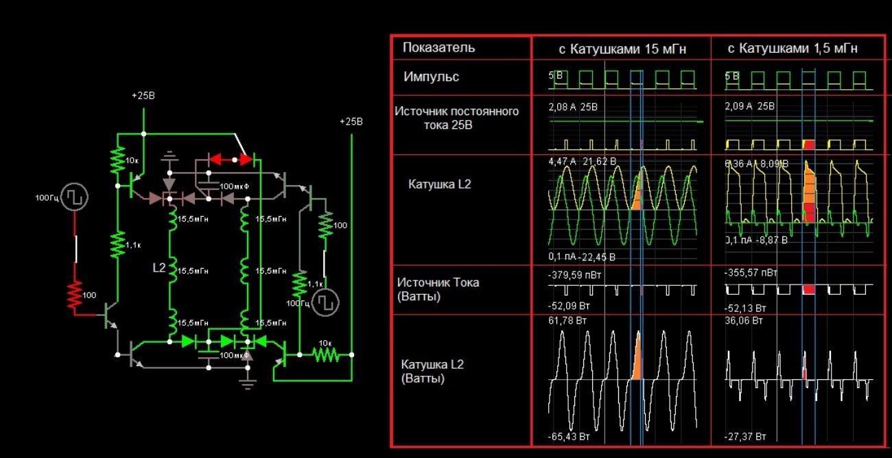
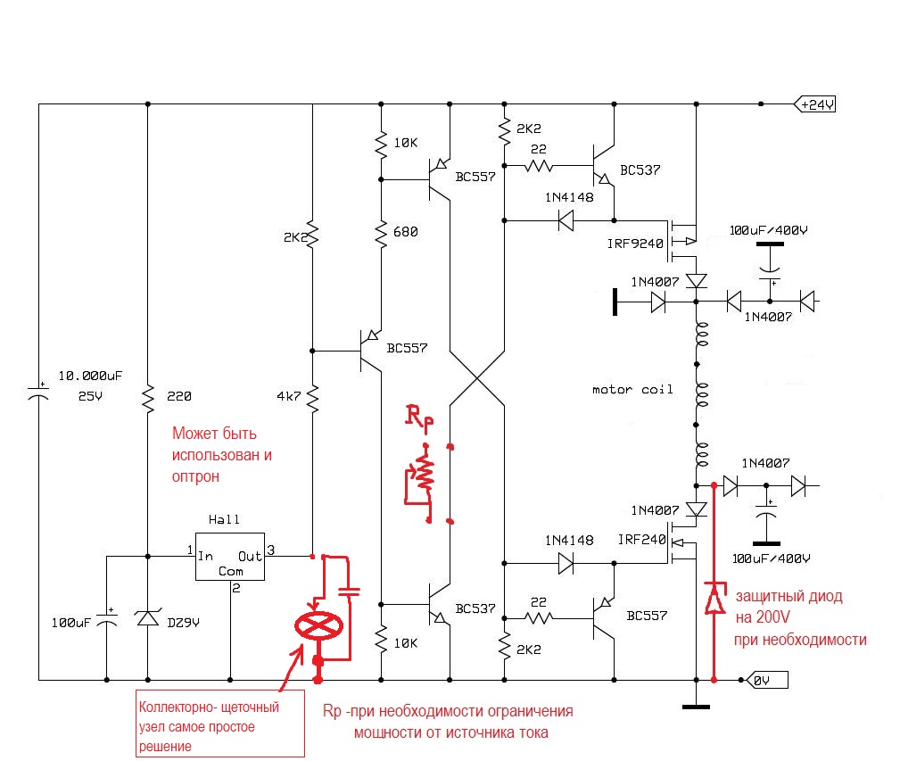


The complexity of this concept lies in its calculation and adjustment. In addition, the upper key must be set to limit the flow of current from the source. With the application of its upper stage generation thread, the system is self-propelled. But the system will not be cheap, there is something to think about.

Other overclocking systems are possible, even without magnets.

Flywheel Generator Project

#14 ·

SkyWatcher wrote:

Hi all, going in a new direction with the flywheel project.
Decided to get rid of belts and pulleys and integrate the generator into the flywheel itself.
Picked up a 10 lb. cast iron weight lifting plate and was glad to find the center hole is accurate from manufacturing.
Then made a shaft adapter for the center hole, which is a tad over 1 inch, using steel epoxy putty in a mold, then drilled 5/8" shaft hole and lathed to fit cast iron plate.
The flywheel rotates very true.

Will then use bedini style pulse motor circuit for propulsion and probably air coils around the rotor/flywheel, for power generation.
This should be more efficient, as the intention is not to generate big power, just power some lights and charge some batteries for this design.
Will be attaching neo magnets to periphery of flywheel to start with, though a separate wood rotor could be made also and have plans to add more flywheel weight if needed.

Working on the structure at the moment.
peace love light
Hi! In fact, you come to the correct formula of the device. I want to encourage you, this technology was implemented in the project VEGA (Ukraine). The upper stage at a certain speed was self-propelled. The disadvantage of the system was the classic synchronous generator MAGLEV (USA). The mass of the rotating rotor also served as an inertial mass.

image_placeholder.svg


At that time I upgraded one such unit. To the owner I had offers even to improve, but he refused having received steady result of work. Its installation worked as an Autonomous source of security alarm, mobile object.

Either way, you need another generator.

Flywheel Generator Project

#10 ·

Good time! The generator, but still the magnetic core of the stator is closed, and then braking when the induction is suitable. Especially if you follow the calculation the greater the rate of interaction of the Magnet and the wire the less need to have incoming mechanical strength. By reducing the speed you increase the result of mechanical torque, for induction current. For example, if you follow the traditional formula of dependence of electrical power and mechanical, you can see that at low speeds, the traditional generator is harder to turn when inducting a current (and you have a traditional synchronous generator).


About your flywheel, I know how to upgrade it. Take three metal tubes with a diameter of 50 mm. Cut the thread from the outside. On both sides, make two screw caps plugs, so that between them there was a gap in the thickness of the flywheel. Pour the lead inside. Achieve a perfect identical weight of all goods. On the flywheel closer to the edge, with a pitch of 120 degrees cut the holes and secure the cargo. You will get concentrated weight distribution and not distributed weight, which will have a beneficial effect on the centrifugal seat.

In order to determine the minimum point of promotion of the flywheel, it is necessary to measure the flow rate of the motor at idle. Then connect to the flywheel and untwist to the point where the flow rate of the engine will approach or be equal to the flow rate of idling. If you have an engine that will not run at idle, so it will be loaded onto the flywheel of the promotion, this means that the flywheel will not be able to be useful to you, as it is a load for itself .

SkyWatcher wrote:

Hi all, Have been working on a flywheel generator, similar to the Chas Campbell device and other similar devices by others.
Powered it up today at 12 volt input, though it is a 24 volt input motor.
It still should have started the flywheel turning at 12 volts, with the permanent magnet alternator in place, though with no load on it.
So the pulley ratio arrangement is not suitable for the small 100 watt scooter drive motor.
Then had to redo the pulley setup and at the moment, still finishing remounting the drive motor in the new position.
Positive, kind and helpful comments welcome.
If you think these types of devices have no merit, then please talk about it in your own thread.
peace love light

Here is a pic of the project at the moment.

In your design have the gearbox (the lever of Archimedes). But the speed of rotation of the flywheel will be small to get anything substantial from your generator. You have the alternator from the car its working speed of approximately 4000 rpm While the torque absorption will correspond to the load circuit. Your design is not new and is used in machines for pressing parts. For such purposes, the devices use massive flywheels with a good shaft in diameter, your shaft is very small to transmit the momentum. The weight of your flywheel is more like the steering wheel of the transmission. In General, good luck, the main work head.
The flywheel is made of wood ? what is its weight and diameter!


Number four is the flywheel in the diagram.
