Skip to content
Stan’s Legacy

johnb003

12 posts · 2 threads started · 3 more in threads this archive does not carry · writing between Feb 2009 and Feb 2009

An identity on Energetic Forum as it was harvested, not an account on this site. Nobody here has claimed it, and nothing connects it to a person by name.

Anyone have tips for constructing vacuum experiments? I wonder if I could create some kind of plexiglass box or clear pvc tube or something, with pressure fittings that could be connected to a running vacuum.

Anyone know how much a vacuum pump suitable for this kind of thing would cost? I think I recall Stanley Meyer had some sort of vacuum hooked up to his cell in the video.

I'm really just interested in studying electric discharges in a vacuum.
I understand how the field would look with two magnets interacting. I guess I was just curious about where the poles were.

Lets say the magnet is 1x2x5 units, and ignoring the the bend. You're saying your single magnet has the poles on the 1x2 side?

But in the picture it's probably on the 2x5 side? Or are you saying they are probably the same, but 2 linked are probably forced together with the same poles so that you have something like this:

N----SS----N
==========
S----NN----S
I see. Interesting that's it's long ways. Too bad though, I think it'd be really cool if the magnetic poles were on the facing sides.

I just got some new magnets in the mail. These ones are very strong, I'm excited to try to use them, but they will seriously hurt my fingers so I need to find a better way of bringing them close together.

`John

Electrotek wrote:

The Hard Drive magnets have N on one end and S on the other end, so the direction of the B field is parallel to the surface. With my setup, both the E field and the B field are in the same direction. So the perpendicular direction is towards the magnet's surface. And the lateral spread of the spark dashes is also a perpendicular direction.
Your hard-drive magnets are like this?...


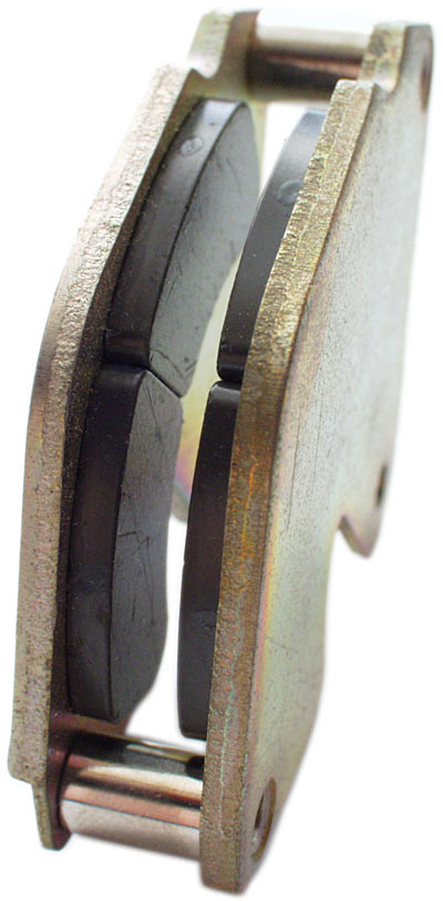
The magnetic poles are on the flat sides right? So if you picture just putting your gap inside this entire mount, wouldn't the B field be perpendicular to your e field?

The B field would be between the N and S facing edges, and the E field would be in the direction of the spark gap right? + to -

Have I misunderstood something?

Or are your magnets N and S the long way for some reason? (such as top to bottom in the picture)
Thanks for the replies!

Here's a description of the spark gap I tried:

I took a chopstick, it was pretty square but also pretty thin, and I taped two wires onto it such that there was a small gap between them. The wires were stiff enough to not move too much, but could be bent into place. I bent them out a little so the spark wasn't right against the magnet. Also the wires were non-magnetic. Then I took another chopstick just like the first and placed it on the other side of the gap so the chopsticks were like rails and the gap was suspended between them in the same direction as the chopsticks. Then I had 4 disk magnets two on the bottom two on the top, such that they clamped down on the chopsticks and held it all together.

I can also take the magnets off and just use the one chopstick by itself supporting the spark gap at the same distance as with the magnetic field.

I ran the power supply connected to the cap and the gap and I get the loud repeated cracking, It sounds like two stones being slapped together really hard. But there's no real audible difference between with magnetic field and without.

I ordered stronger magnets, so I'll give those a try this weekend, but otherwise I'm puzzled why it's not working. As I mentioned I tried this experiment again with a larger gap size, but though the cracking was less frequent and much louder, there was no difference between with and without the magnetic field that I could detect.

Xenomorph:
Yeah, the shunt resistors are rated for 10W of power each, yet they were only 1.5 ohm. And I figured if P = V^2/R, solve for voltage:

V = sqrt(10*1.5) = sqrt(15) = close to, but less than 4.

So, since my supply is 12V, I need to put them in series, which gave me 6 ohm of resistance, so then I was like, well I want more current, so I'll put 2 more of these chains in parallel.

It's probably not needed with the inductance of the coil and all, but it doesn't really hurt the HV, and if something goes wrong in my 555 then once the field stabilizes the inductance goes down and suddenly I'm drawing a lot of current it would fry the mosfet probably burn up the flyback, and blow my fuse :P

Anyway that video looks interesting, but I'll have to wait until tonight to check it out.

sucahyo:
That's precisely the setup I was referring to from Tesla. I wish I could build something study that resembles that layout but it's hard without any machining equipment.

Electrotek:
I would think with bent electrodes, you have to be careful to make sure the magnet blows the flame away from the rails and not along them. Also I'm curious why your spark was drawn into the magnets and not perpendicular to them, I thought with the lorentz force it would be perpendicular to both the wire E field, and the B field.

`John
Also where does everybody get the materials for their experiments?

I feel handicapped when it comes to constructing nice rigs. Even for a spark gap, I mean sure I can go to home depot and find metal rods and probably a block of wood, but I feel like I'm trying to make fire with twigs and stones.

What about mounting brackets, or what if I wanted some kind of magnetic metal plate that I could adjust into place to fine tune the poles of an electromagnet or something. Or what about the shape of the rods, perhaps I want them tapered, or maybe even threaded near the neck so I can adjust the gap size.

What do people do these days, if you don't have the equipment to machine or mold everything yourself? Is there a cost effective solution to prototyping?

`John
Hello.

I've been trying to follow Tesla's descriptions for creating high frequency spark gap discharges from a capacitor, and I'm having some trouble getting really high frequencies.

As I understand it, Tesla was using a magnetically quenched spark gap, such that when the capacitor discharge is formed it would immediately be blown out. However, so far I haven't been able to produce any noticeable effect with a strong magnetic field.

So far I've built a hv power supply using a flyback transformer and a 555 timer:

edit - 2/23/09 - Updated video to show more detail of the power supply:
YouTube - High Voltage Power Supply

edit - 2/25/09 - Added a new video with oscilloscope readings:
YouTube - HV Power Supply Oscilloscope Readings

So I have my hv output connected to a hv capacitor, and I've started with a very small spark gap. I get rapid discharges, but they are pretty distinct and I can tell it's not that high of a frequency. I tried putting a fairly strong magnetic field surrounding the spark gap, but it sounds very much the same. I thought maybe the spark gap has to be larger so the discharge is more intense for the for the Lorentz forces to have a stronger action. So I made the gap wider but still I can't really make out any observable difference with the magnetic field vs without.

In the article from Tesla "On Light and Other High Frequency Phenomenon" he clearly states that with the magnetically quenched spark gap, the sound of the discharge is more like a gun shot which he says is because the discharge is formed and broken several times. I guess he means formed and broken several times for what would have been a single discharge.


Has anyone created a nice magnetically quenched spark gap, and noticed a considerable difference compared to the same without the magnetic field? Tesla's assembly seemed pretty nice, especially since he was using an electromagnet which he could vary the intensity to fit his needs.

Thanks,
`John
Peter Lindemann wrote:

Hi Guys,

The only place I have ever seen The Dissipation of Electricity mentioned, is in Secrets of Cold War Technology, by Gerry Vassilatos. This lecture was supposedly given in December of 1892. I have never found any other reference to it.

Having looked for this lecture for years, I finally "wised up" and realized what was going on. In his next lecture in the series, Tesla covers the same information again. So, the lecture On Light and other High Frequency Phenomena, given in both February and March of 1893, everything you are looking for......is right before your eyes!

You can find this lecture on the web, or download it from my website at:


Enjoy,

Peter
Ahhh, thanks very much Peter.

Speaking of Secrets of Cold War Technology, I tried getting my hands on this as well and have a had no success. The sources I found in the US were listing prices like around $700 US or other ridiculous figures. I actually found a store who claimed to have it for a reasonable price in the UK, and I tried to order overseas, but then replied saying it was out of stock and they had to order it from their supplier and eventually determined they couldn't get it from their supplier either, as it's out of print. So they gave up.

Do you know where I can get a copy of this for under $100?

Thanks again,

`John

amigo wrote:

johnb003,

see here, maybe the article is in there:

Tesla Said, compiled by John Ratzlaff.pdf
Found the same article: On the dissipation of electrical energy of the hertz resonator.

But not one of the name, "The Dissipation of Electricity". I liked this version of the article about the hertz resonator, because it was not subject to mistaken OCR. However it was missing pages.

Still curious if there is another article.

`John

Inquorate wrote:

Pepe's Tesla Pages

If it's not on this site, it's probably in a vault somewhere, never to see the light of day again.

Click on tesla link

Btw, if anyone wants to save any of those documents as a text and email them to me at [email protected] it'd be hugely appreciated, as my phone won't open the files as they are.
Hey, I went to the page, and found the article you referred to: "On the dissipation of electrical energy of the hertz resonator".

I just read through it carefully and it's very interesting, and definitely gives me the impression on I'm the right track. Though I'm not sure if it's the paper I'm looking for. There are several references to an article "The Dissipation of Electricity", which are either incorrectly referenced or there is another article.

Anyone know if the other article does exist?

In this article it clearly shows that Tesla was not convinced that Hertz had considered everything. He seemed to think that though the conclusions of the relationship between the transmission and receiver were essentially correct, there was another factor not considered, that of the air. It seems like he had experimental evidence to support this, and explains several of his findings, but not in great detail.

I feel that in an attempt to verify the results Hertz concluded, Tesla discovered something and this article highlights his discovery, but perhaps he also published a lecture detailing this discovery?

Thanks.
`John

Inquorate wrote:

Dude, that's at least 50 kv.


Which is apparently doable with a flyback

POWERLABS' High Voltage Solid State Flyback Driver

Ah, I suggest a home made salt water capacitor, (use baking soda instead of salt) or Alfoil with several A4 sheet protectors between each sheet of foil..

50 000 volts. Be really careful.
Yeah, I tried that driver first. I'm running this off of a car battery, despite the risk, and well with that much current the transistor just couldn't handle it, even with a beefy heat sink. I like how that system self resonates, but I'm using the 555 timer and a power mosfet so I have a lot more control. At around 4khz I get a pretty high pitch sound that changes based on arc length, and at 48khz the arc stays super sonic except for very small arc lengths (that's opposite of what I expected.) I thought at longer arcs the discharge rate would be slower. Maybe it's just resonating at certain lengths amplifying an audible frequency.

Anyway, the main difference at 48 khz, aside from supersonic is that the arc is stronger and shifts around more as it doesn't seem to want to take the same path through the ionized air. At 4.8 khz it's pretty stable.

I've run the transformer for up to 5 minutes without anything even getting warm so I'm pretty happy with my design.

Anyway I'm still curious about the capacitors, is it bad to use a charge voltage way above the capacitor's rated voltage? or does it only matter how high the stored voltage is?

Since my spark gap for the cap is very small it discharges before it gets too high.

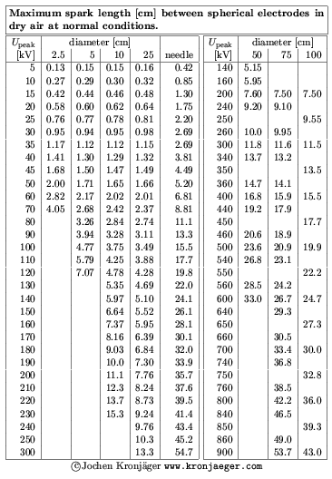
Thanks for the table link btw. However my gap is between exposed ends of wires so it's not like spherical electrodes. Though I don't doubt it's still around 50kv.

`John
Has anyone come across a copy of this lecture by Nikola Tesla?

There's so much information out there, but sometimes it's hard to get to the root of it.

---

I'm finally getting some practical hands on experience with this stuff. My goal is to start with the basics and see if I can produce the same conditions in which Tesla first observed radiant energy.

I have succeeded in building a high voltage power supply, I built it from a simple 555 timer and a flyback transformer from a CRT monitor. The nice thing about it, is the transformer has diodes between each layer of the secondary, so I don't need to try to rectify my HV output. The downside is I only get a half-wave, but oh well, it's a start.

From there I'm able to charge a high voltage capacitor and discharge that over a spark gap.

I've got a few HV capacitors, one is from a microwave with a pretty high capacitance, and another from the CRT logic board which has a much lower capacitance. Obviously I can get much more powerful impulses from the microwave capacitor, but I can charge the smaller one much more rapidly giving me higher frequency discharges.

However like I said my aim is to see if I can detect the radiant discharge that Tesla described in the lecture, so at least to start with, I'm not concerned with high frequencies.

So, out of curiosity, my capacitor is rated for about 2kv, and I have my spark gap set very small, a few mm at most. So I'm expecting that I'll never get a charge up to 2kv, but what I'm worried about is my HV power supply produces discharges in air about 5-7 cm. Which I figure is a lot higher than 2kv. So is the capacitor safe to be charged with voltages that high as long as it doesn't reach that voltage or am I likely to have fried capacitors soon?

Now I need to find a way to force these discharges to be unidirectional. I have a single hv diode that came from the microwave and it seems like it can handle pretty high current but I'm hesitant to discharge the cap through it, as I can imagine that the discharge might break it.

Any thoughts?

I have a site I'll be posting all of the info from my experiment soon.

Thanks,
`John