Skip to content
Stan’s Legacy

Armagdn03

36 posts · 3 threads started · 229 more in threads this archive does not carry · writing between Sep 2009 and Apr 2012

An identity on Energetic Forum as it was harvested, not an account on this site. Nobody here has claimed it, and nothing connects it to a person by name.

Cross Field Capacitor

#3 ·

Here is the demonstration of reduction of capacity. Imagine charging to thousands of volts, the discharge will be hundreds of amps, the results should be good!

YouTube - MOV03700

Cross Field Capacitor

#2 ·

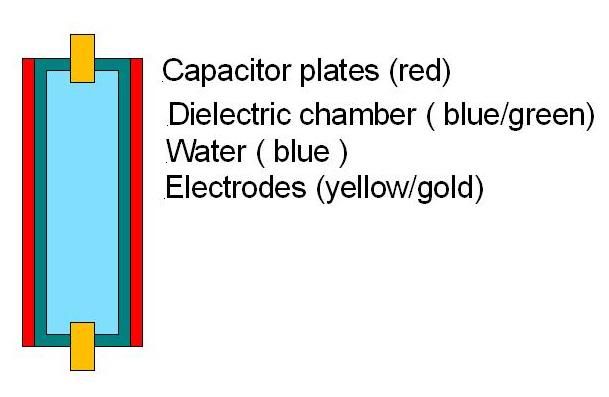
here is an "artist rendition" by user Dragon, who is brilliant with his hands (much like all of you!)

[/QUOTE]

Tonight, I will upload one of my first proof of concept experiments and load it.

Cross Field Capacitor

#1 ·

Here is the concept I begun testing and intend to finish, which I believe is very strong. I thought some might find the concept interesting.

Imagine an electrolyser cell, yet simplified.

There are only two plates and each is covered with a dielectric.

In between the plates is water.

Because of the dielectric, there is no way for charge to leave one plate transit the water and end on the other plate, Rather the plates act more like a capacitor.

If you were to run a current through the water, (from two electrodes see rough diagram below) you would notice a sharp decrease in the capacitance of the plates.

-------------------------
x~~~~~~~~~~~~~~~x
-------------------------

The dashed lines above are the capacitor plates with insulation, in between them is water. The "x" marks are electrodes to cause a current to run through the water parallel to the plates. The squiggly lines are the water. If you imagine the fields, you would have the water molicules aligning its poles in the plate to plate (vertical in this portrayal) direction. The current is going from electrode to electrode, in the horizontal direction, thus the dielectric field of the capacitor, and the current are orthogonal or perpendicular to each other.

Here is where the magic happens. It is known to those skilled in the art (brushing up on my patent writing skills That to decrease the capacitance of a charged capacitor causes an increase in the energy state. This arises from the law of conservation of charge, and is explained very well in the Hidink patent 4095156. This is the fundamental concept behind parametrics, variation of the parameters of a system to affect an increase in energy, in this case, we are talking about capacitance.

So now that you understand the layout of the simple cell, and the concept of decreasing capacitance causing an increase in energy, you will see the simple elegance of what I am trying to do.

Imagine charging such a capacitor to some very high voltage (I am working with 12kv). Now discharge this capacitor through its own dielectric (water). As the discharge occurs, the increase in current through the water, causes a sharp decrease in capacitance of the cell!Our discharge diminishes the very capacitance that holds it. It is known that the area under the curve in an oscilloscope reading equates to the energy in the pulse. Here one discharge of a normal capacitor has an area x. Here the discharge should be (and preliminary tests show this to be correct) larger than X. To what degree I am not sure yet.

Now imagine what this means. We will have two outputs here. One will be gas liberated from the electrodes, the other will be our electrical discharge. My plan is to recycle the discharge back into the capacitor from whence it came, thus completing one cycle.

I call this device the cross field cell, as it plays dielectric force against current. (the two being perpendicular to each other).
Once upon a time, I was forced to take an 8:00 am physics class, for which my friend and I were too advanced. We bargained with the professor to let us do a project that showed our mental prowess and got the OK to build an electromagnetic linear accelerator (rail gun) instead of having to wake up at such a terrible hour.

One of the components was a capacitor bank that was several farads at several thousand volts. We used to awe people by sticking one electrode in a glass of water, then using the other to start the top of the water on fire through arc discharge electrolysis. How cool that you can start water on fire!

One day we were working, and I reached my hand out to disconnect the bank, not realizing it was charged...........My friend from across the room threw a text book with the accuracy of a sniper and yelled, WTF are you doing!!!. My hand was whacked away instead of blown to smithereens.

I was young and dumb, and never have and never will make a similar mistake again!

Remember, a smart man learns from his mistakes, a genius learns from others....so learn from this one...Electricity is fun...and incredibly dangerous.

Orbo

#4 ·

Batteries have relatively flat charge and discharge curves, capacitors very much do not, this makes a huge difference in their operation, and they are not interchangeable in careful energy management systems

nilrehob wrote:

@Armagdn03

I guess what you described in the first post is exactly what Core of the physical effect discovered by Andrey Melnichenko is doing?

/Hob
Absolutely not! I take this quote from the text given,

"Free magnetic field Bi2 does not form flux linkage with magnetizing wind. The electric energy source does not spend any energy on free magnetic filed formation. Field Bi2 does not come into the formula of work onto magnetisation.
All the electric energy costs in a wind are restricted (source current can not use more!) only by those magnetic energy which establishes the connection with magnetisation wind. Field Bi2 and magnetic energy connected with it appears absolutely for nothing without additional energy cost."

In my theory, there is a disconnect, but it is not 100 percent. There definitely is back talk as you can see by my maths, graphs, and descriptions. I would be very impressed indeed if he can say that the field of "bi2 does not come into the formula" and would say this probably means the gentleman has not completely done their homework. And key in this theory is the balancing point by where field induced and field returned per lenz like reaction are situated to return most power.

dragon wrote:

Armagdn03, what size diameter, length and threads per inch do you need ? I may be able to make this up for you.
WOW! that would be fantastic, I would compensate you of course. The larger the diameter the better, I usually can only find around 4" pvc at the hardware store. Let me take some measurements and see what might work.

What are your limits in terms of size?

Tecstatic wrote:

Hi Andrew,

Thank you very much for these posts

I'm glad I did the experiments with my SEC cubes. Your explanations fit nicely with my observations. I think you are right my SEC cubes are some kind of hybrid. I have seen both the wide band and the capacitive transformation using differently sized spheres.

I have had this in my head for some time, and I really feel some pieces has now been added to the puzzle.

Although I have not responded much to your helping hints previously, your advice has not been forgotten.

Please bear with me, I'm still a newbie in FE. It is now just over 2 years since I got awakened by a YT video about Stanley Meyer.

But your advice made me realize, that I needed some equipment to do some more experimentation, Thats why I started my running thread, as my need for experimenting equipment has lots in common with much other stuff in this field. I also did it to provide some help to h20power & friends, as EE's are not an excessive entity here, alt least not regarding providing practical help.

So I do an attempt to make some easy to use PWM controllers, where we have the possibility to add closed loop regulation, when we (hopefully) arrive at something useful and flexible for a broad range of experiments.

I will follow your thread, so please keep up the good work, and your very clear explanations ease the digestion of this subject a lot.

So please continue even though you get nearly no feedback. Now I only get feedback from bussi04, and sometimes I feel I could as well communicate directly.

But IMO the larger picture is about trying educating many, so they can spend more time experimenting instead of fighting some electronic control circuits necessary for the experiments.

Eric
Thank you Eric for your encouragement.

Right now, I believe its current embodiment is not all it could be. For example, placement of the top load changes the frequency of the resonant structure by about 10 %, which is pretty bad. This means that the rest of the resonant action in the capacitive end of the spectrum is happening within the coil and running a neon along the length of it will verify this. In order take it to the next level, one would need to have an inductor with spaced windings leaving as much of the capacitance as possible within the topload. This also will increase the Q of the circuit, as you are removing un wanted parasitic capacitance.

In order to get a good inductor one would need a large-ish diameter coil with spacing for the windings. If anybody has a lathe that could turn some PVC with a helical grove for windings, I would be really grateful to see if something like this could be made.

There are dissadvantages to taking the capacitive route, mainly that the capacitive end of the spectrum interacts heavily with biological systems, and hence biological systems being primarily water, act as a load to the transmitter. This means that you the inventor can detune the system, and dissipate some of its energy in you!

It would pay to try and accomplish the same transformer action via inductors, similar to what was displayed by MIT with their wireless transfer device several years ago.
This is also the bulk of the process involved in the "room full of tuning forks" analogy, or the radio tower with infinite crystal radios. They will feedback to the source, this can be experimentally shown, however the process leaves one with excess energy.


YouTube - Maximum transmission point
YouTube - Evolution of the Eccentric Transformer

It was later discovered that one needs to isolate either the capacitive or magnetic elements in order to have the purest experiment.

YouTube - evolution 2.wmv


I have heard at more than one time someone in a youtube video create a wireless power transmission device and ask Dr. Stiffler to comment on why it was supposedly doing the same thing as a SEC circuit. 99% of the time it is not doing the same thing. SEC technology is an ultra-wideband oscillator with a huge harmonic range. Most of the time what they are probably referring to is the effect described here, this is not to say that eccentric transformer action does not come into play in some SEC technology.

One of these videos also gives a possible explanation to the Kapanadze patent and videos.

Exploding water

#12 ·

Vortex wrote:

Oxygen explodes or shall we say burns very quickly, WITHOUT any fuel.
(see the video)

Is oxygen not a fuel?
What really burns then, the oxygen or the fuel?

YouTube - O2 CYLINDER EXPLOSION
I don't believe the explosion in this video was combustion. I have heard tales of this particular accident from various people, and it seems it was a defective cylinder releasing its pressure.

here are is another interesting design, click on the user chanel and you will find tons of very interesting steam turbines.

YouTube - Karsten Heron's Turbine

Exploding water

#8 ·

This video is brought to you by a gentleman that goes by the name of Flavoredcoffeeguy, He has many interesting concepts, and I would recommend watching all of his videos, however the one below pertains to this discussion.

YouTube - How to Burn Water

enjoy
Great post, thank you. Many people may not know it but Eric Dollard lived with Farnsworth's son, its all related, and you are doing a good job of pointing people to your connections. thanks.