Visualizing Current Saturation
4 July 2022
Continued From: Step Charge as a function of Pulse Period
By: Chris Bake
ABSTRACT
- Direct probing a toroid current sensor (channel 4 green) between the inductor and cell reveals that current step charges inversely with the positive by reference of the TIP120 pull-down.
- Also of critical note: a "current saturation" point is identifiable seemingly independent of the voltage step charge, pulse count can be reduced to eliminate the saturated portion of the Pulse train. Changing inductance also moves the current saturation limit in or out.
- And extending the gate period longer increases the current saturable limit
Current Sensor
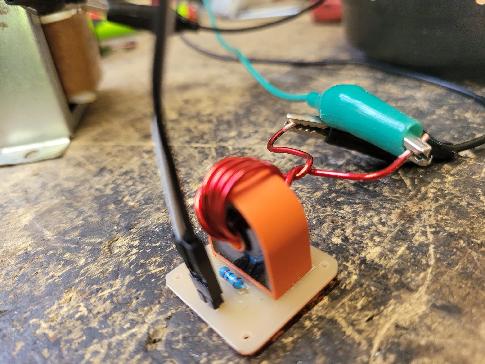
Constructed from a 5A AC single phase sensor module for Arduino. 4 wraps of 10ga enameled magnet wire wrapped around the toroid to provide enough inductance for the sensor to have a higher level output voltage reference.
Channel 4 - GREEN - Shows current pulses in the opposite phase of the voltage. Current sensor is located between the inductor and cell.
A Current Saturation limit is visible in the pulse train, virtually indistinguishable from the continued voltage pulse step charge.
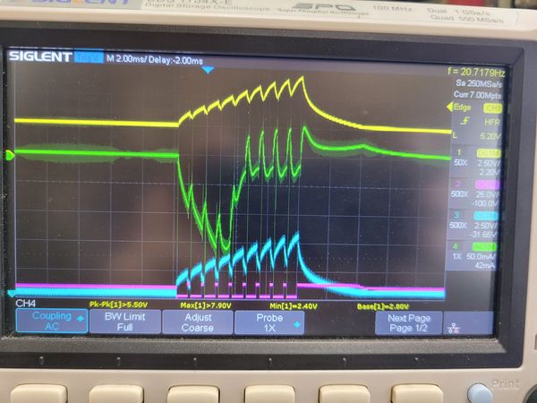
Several adjustments can be made to prevent the saturated region from occurring:
Reducing the number of pulses can remove the saturated portion of the pulse train.
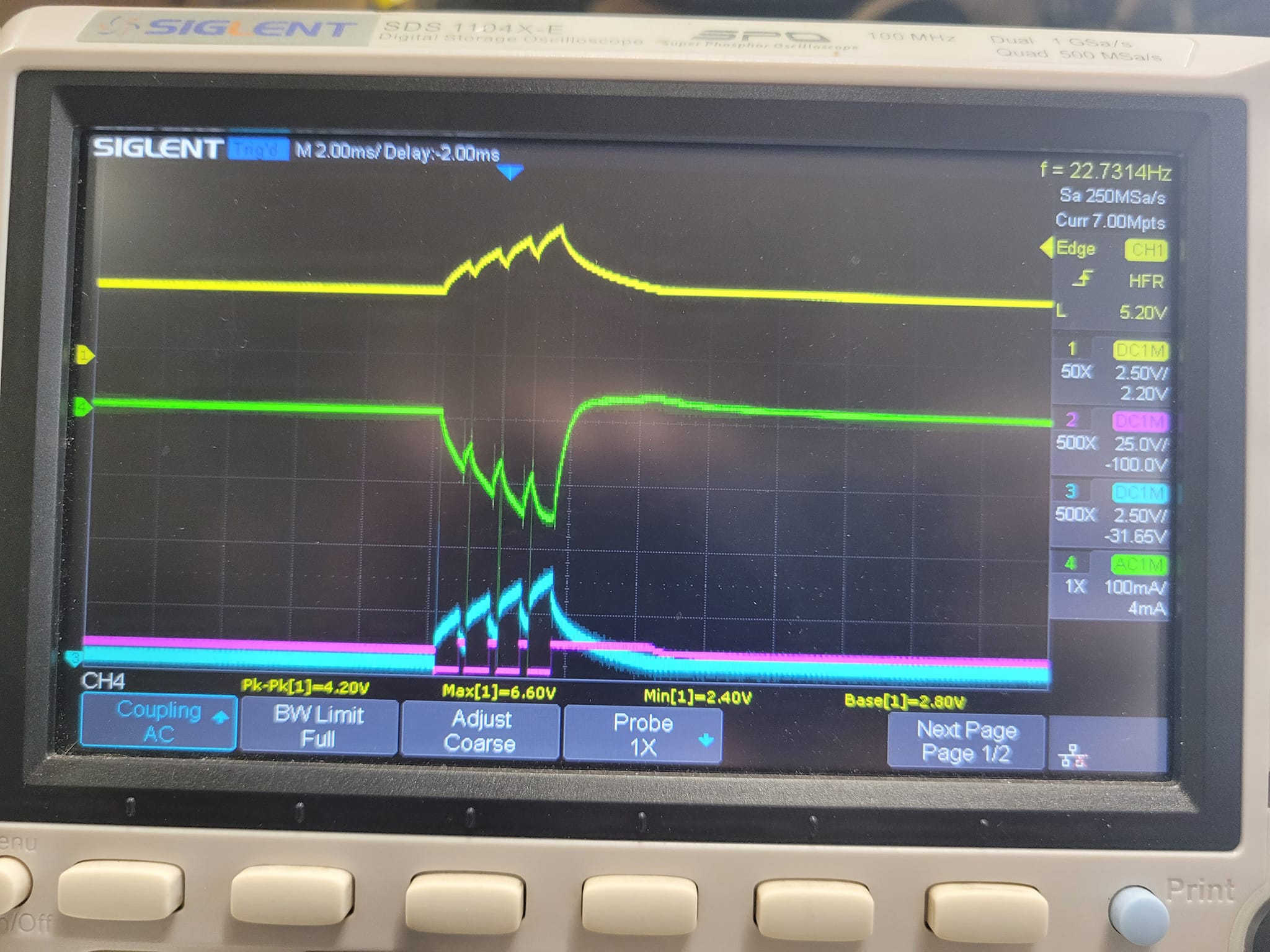
Increasing the Gate Spacing improves the pulse's ability to remain out of saturation.
Reducing the on time Width also improves conditions, but at the tradeoff of less current during ON times, impacting the pulse's ability to "forward charge" the inductor. (reduction in net amplitude of step charge)