patent · US5997812
Methods and apparatus for the application of combined fields to disinfect fluids
7 December 1999
Page 1 — bibliographic record
United States Patent (19) 11 Patent Number: 5,997,812 Burnham et al. (45) Date of Patent: *Dec. 7, 1999 54 METHODS AND APPARATUS FOR THE 4,008,045 2/1977 Free ........................................ 250/436 APPLICATION OF COMBINED FELDS TO 4.013,063 3/1977 Bucalo . ... 128/843 DISINFECT FLUIDS 4.017,735 4/1977 Siegel. ... 250/430 4,026,805 5/1977 Fowler .................................... 210/223 (75) Inventors: Jeffrey C. Burnham, Naples, Fla.; 4,028,246 6/1977 Lund ....................................... 210/151 Robert S. Reimers, Metairie, La., Jery 4,050,426 9/1977 Sanderson ... 123/538 4,065.386 12/1977 Rigby ....... ... 210/695
E. Barton, Naples, Fla.; Warren S. 4,079,002 3/1978 Iannicelli ........ ... 210/695 Bankston, Covington, La. 4,082,665 4/1978 Schneider et al. .. ... 210/91 4,108,767 8/1978 Cooper ............ ... 210/695 73) Assignees: Coolant Treatment Systems, L.L.C., 4,110,208 8/1978 Neal ..... ... 210/695 Naples, Fla.; Administrators of The 4,141,686 2/1979 Lewis ... ... 250/436 Tulane Educational Fund, New 4,141,830 2/1979 Last ...... ... 210/748 Orleans, La. 4,146,479 3/1979 Brown .. ... 210/222 4,188,296 2/1980 Fujita ...................................... 210/222
Notice: This patent issued on a continued pros 4,189,363 2/1980 Beitzel . ... 204/158.2 ecution application filed under 37 CFR 4,210,535 7/1980 Risk ........................................ 210/222 1.53(d), and is subject to the twenty year 4,214,962 7/1980 Pincon . 204/157.44 4,229,389 10/1980 Granger ... ... 261/122.1 patent term provisions of 35 U.S.C. 4,230,571 10/1980 Dadd ....................................... 210/760
(List continued on next page.)
Appl. No.: 08/690,982 FOREIGN PATENT DOCUMENTS Filed: Aug. 1, 1996 0712807 10/1995 European Pat. Off. .......... CO2F 1/48
Related U.S. Application Data 25 26 674 A1 6/1977 Germany ... ... CO2B 1/02 WO9509815 10/1994 WIPO ..... ... CO2F 1/32
Continuation-in-part of application No. 08/667,028, Jun. 20, WO9622944 1/1996 WIPO ............................. CO2F 1/463
OTHER PUBLICATIONS
Int. Cl. ...................................................... A61L 2700
U.S. Cl. ............................ 422/24; 210/695; 210/748; Patent Abstracts of Japan. vol. 015, No. 080 (C-0810), Feb.
Field of Search .................................... 422/24, 186.3, Patent Abstracts of Japan. vol. 015, No. 202 (C–0834), May 422/23, 1; 210/695, 754, 748, 760, 764, 23, 1991 (SUIDO KIKO KK).
766, 407; 250/455.11 Patent Abstracts of Japan. vol. 095, No. 009, Oct. 31, 1995
(PASUKOENG KK).
References Cited
Primary Examiner Krisanne Thornton
2,147,857 2/1939 O’Brein. 57 ABSTRACT
3,060,339 10/1962 Moriya. This invention relates to apparatus and methods for the 3,230,137 1/1966 Ellison. treatment of fluids with magnetic fields and, in particular, to 3,433,946 3/1969 Hardwick. the disinfection of contaminated fluids by treating the fluids 3,456,107 7/1969 Robertson. with a high-gauSS magnet followed by ultraViolet radiation. 3,462,597 8/1969 Young. Fluids can accumulate organic and non-organic contami
3,485,576 12/1969 McRae et al.. nants from multiple and diverse Sources. Magnetic treatment 3,527,940 9/1970 Balanca et al.. enhances the ability to Separate hydrophobic contaminants 3,550,782 12/1970 Veloz. from the fluid and the ability of that fluid to be disinfected. 3,562.520 2/1971 Hippen .................................... 250/372 A wide variety of fluids can be treated with these methods 3,567,026 3/1971 ... 210/222 including water to be made potable, industrial water and 3,608,718 9/1971 Aubrey, Jr. et al. .................... 209/214 other fluids Such as coolants and lubricants, oils, petro 3,634.025 1/1972 Landry .................................... 250/436 chemicals. Such as fuels, and beverages. Further, fluid can be 3,635,819 1/1972 Kaiser ....... ... 210/634 exposed to UV radiation at a flow rate sufficient to prevent 3,659,096 4/1972 Kompanek ... 422/24 occlusion of UV-transmissible Surfaces in the disinfection 3,669,274 6/1972 Happ et al. ............................. 210/222 System by contaminants in the fluid or by removing a Set
3,676,337 7/1972 Kolm ...................................... 210/695 amount of those contaminants. Using these methods, micro 3,683,177 8/1972 Veloz. ...................................... 250/435 organism levels can be Substantially decreased with a 3,700,406 10/1972 Landry. reduced need for biocides or other anti-bacterial or anti 3,767,918 10/1973 Graybeal ................................. 250/433 fungal agents. These methods are highly effective at remov 3,814,680 6/1974 Wood. ing contaminants and extending the useful life of fluids Such 3,837,800 9/1974 Wood ........................................ 422/24 as coolants and reducing or eliminating the risks posed to 3,844,943 10/1974 Duval ... ... 210/695 workers by heavily contaminated or biocide-treated cool 3,889,123 6/1975 Bosshard ................................... 387/67 antS.
3,894,236 7/1975 Hazelrigg. ... 250/435 3,923,663 12/1975 Reid ... ... 210/251 3,948,772 4/1976 Ellner ..................................... 21.0/96.1 38 Claims, 11 Drawing Sheets
Page 2
4,273,660 6/1981 Beitzel 210/760 4.952,812 8/1990 Miripol et al...................... 250/455.11 21 - eitzel .................................... 4.959,142 9/1990 Dempo .................................... 210/167 3. 18.R. S. 2. 4.968,437 11/1990 Noll et al. ... 210/748 4.336.223 6/1982 Hillman - - - - 422/24 4.968,891 11/1990 Jhawar et al. 250/438 4,367.410 1/1983 Wood ... ... 250/431 4,971,687 11/1990 Anderson .................................. 210/85 4,372852 2/1983 Kovacs. ... 210/222 4,983,307 1/1991 Nesathural .............................. 210/748 4372.860 2/1983 Kaas ..... ... 210/748 5,006,244 4/1991 Maarschalkerweerd ................ 210/243 4,381,754 5/1983 Heckel ... ... 123/538 5,019,256 5/1991. Ifill et al. ........... 210/232 4,382.866 5/1983 Johnson . ... 210/748 5,026,477 6/1991 Yen ...... 210/169 4,396,582 8/1983 Kodera ... ... 422/300 5,120,450 6/1992 Stanley, Jr. 210/748 4,400.270 8/1983 Hillman . ... 210/103 5,178,758 1/1993 Hwang .................................... 210/256 4,414,951 11/1983 Saneto ........ ... 123/538 5,207,921 5/1993 Vincent ................................... 210/704 4,428,837 1/1984 Kronenberg ... 210/222 5,230,792 7/1993 Sauska et al. ... 21.0/97 4,438,337 3/1984 Forrat............ ... 250/436 5,234,606 8/1993 Kazama et al. . 210/748 4,460,516 7/1984 Kapitanov et al. ......................... 261/1 5.248,437 9/1993 Forrest ........ 210/695 4,467.206 8/1984 Taylor ............ ... 250/435 5,258,124 11/1993 Bolton et al. 210/748 4,469,076 9/1984 Wolff ... ... 123/538 5,266,215 11/1993 Engelhard 210/748 4,469,835 9/1984 Laurin. ... 524/349 5,288,461 2/1994 Gray ......... ... 422/24 4,471,225 9/1984 Hillman ............ ... 250/436 5,322,569 6/1994 Titus et al. .................................. 134/1 4,482,809 11/1984 Maarschalkerweerd . ... 250/436 5,332,388 7/1994 Schuerch et al. ... 422/291 4,495,040 1/1985 Panico .................. ... 204/155 5,352,359 10/1994 Nagai et al. ... 210/192 4,519,919 5/1985 Whyte et al. ... 210/695 5,366,705 11/1994 Reidy .......... 422/243 4,534.282 8/1985 Marinoza ... ... 99/451 5,368,826 11/1994 Weltz et al. 422/243 4,538,582 9/1985 Wakuta ...... ... 123/538 5,376,281 12/1994 Safta .............. 210/748 4,563,286 1/1986 Johnson et al. ... 210/721 5,395,592 3/1995 Bolleman et al. . 422/128 4,568,901 2/1986 Adam ............. ... 335/305 5,411,143 5/1995 Greene . 210/222 4,602,162 7/1986 Sperry, III et al. 250/436 5,433,738 7/1995 Stinson ... ... 604/92 4,615,799 10/1986 Mortensen ........ ... 210/177 5,439,595 8/1995 Downey, Jr. 210/748 4,655,933 4/1987 Johnson et al. 210/721 5,441,647 8/1995 Wascher et al. ... 210/695 4,694,179 9/1987 Lew et al. ... ... 250/431 5,443,719 8/1995 Johnson et al. . ... 210/101 4,716,024 12/1987 Pera ........ 422/186.01 5,460,718 10/1995 Weck et al. . ... 210/205 4,751,392 6/1988 Wiesmann .. ... 250/429 5,466,367 11/1995 Coate et al. ... ... 210/96.1 4,752,401 6/1988 Bodenstein. ... 210/746 5,468.378 11/1995 de la Toree Barreiro ... 210/192 4,757,205 7/1988 Latel ....................................... 250/435 5,480,557 1/1996 Kawasaki et al. ...................... 210/695 4,766,321 8/1988 Lew et al. ............................... 250/431 5,494,585 2/1996 Cox ......................................... 210/748 4,767,932 8/1988 Ellner ...... ... 250/435 5,503,800 4/1996 Free ... 422/24 4,769,131 9/1988 Noll et al. ................................. 210/85 5,504,335 4/1996 Maarschalkerweerd ................ 250/435 4,798,702 1/1989 Tucker ...................................... 422/24 5,505,904 4/1996 Haidinger et al. ........................ 422/24 4,849,115 7/1989 Cole et al. ... 210/748 5,527,426 6/1996 Marwah et al. ............................ 162/5 4,857,204 8/1989 Joklik...................................... 210/695 5,529,688 6/1996 Kacarov et al. ........................ 210/222 4.866,282 9/1989 Miripol et al...................... 250/455.11 5,534,156 7/1996 Sanderson ............................... 210/695 4,872,980 10/1989 Maarschalkerweerd ................ 210/243 5,540,835 7/1996 Sanderson 210/167 4,897,246 1/1990 Peterson ............................... 422/186.3 5,597,479 1/1997 Johnson .................................. 210/192 4,904,874 2/1990 Ellner ...................................... 250/436 5,622,622 4/1997 Johnson .................................. 210/192 4,909,931 3/1990 Bibi ........................................... 210/85 5,635,059 6/1997 Johnson .................................. 210/192
Page 3
Drawing sheet — no readable text.
Page 4
Drawing sheet — no readable text.
Page 5
Drawing sheet — no readable text.
Page 6
Drawing sheet — no readable text.
Page 7
Drawing sheet — no readable text.
Page 8
Drawing sheet — no readable text.
Page 9
Drawing sheet — no readable text.
Page 10
Drawing sheet — no readable text.
Page 11
Drawing sheet — no readable text.
Page 12
Drawing sheet — no readable text.
Page 13
Drawing sheet — no readable text.
Page 14
METHODS AND APPARATUS FOR THE that UV radiation would penetrate the clear liquid to kill APPLICATION OF COMBINED FIELDS TO offending microorganisms. The conventional technology of DISINFECT FLUIDS UV treatment is limited because total quartz Systems have a tendency to foul easily and maintenance costs were high.
REFERENCE TO RELATED APPLICATIONS 5 UV treatment proved to be unsuccessful for industrial fluids Such as coolants, as coolants are opaque, or Substantially So,
This patent application is a continuation-in-part of United and often contain significant levels of contaminants Such as States patent application, Ser. No. 08/667,028, filed Jun. 20, hydraulic and way oils and ferric compounds and complexes 1996. which are highly occlusive to ultraviolet light. Under these constraints, ultraViolet radiation cannot pass more than a
BACKGROUND OF THE INVENTION very Small distance, if at all, into the fluid stream (e.g. U.S. 1. Field of the Invention Pat. No. 3,456,107). These contaminants and coolants This invention relates to apparatus and methods for the adhering UV blocked
transmission directly and also indirectly by wall Surfaces of Submerged quartz, UV lamps or disinfection of fluids and, in particular, to exposing fluids to to the inner surfaces of the UV transmissible tubing in a dry magnetic fields and ultraViolet radiation. 15
System design, wherein UV lamps are kept Separated from 2. Description of the Background the fluid being treated.
Industrial fluids Such as machine tool coolants, cooling A number of measures to prevent the degradation of tower water and organic lubricants traditionally possess industrial fluids by microorganisms have been attempted fairly short useful lives. Microbial contaminants find their with the objective of prolonging the life of the fluid and way into these fluids and proliferate. Microorganisms feed reducing odors and health risks associated with fluid spoil on fluid components as well as contaminants that leak into age. To minimize these risks and the hazards of contami the fluid. AS the microorganisms flourish, the fluid becomes nated coolant fluids, many facilities add appreciable levels even more inviting to further growth as generation after of various biocide fluids to kill and inhibit the growth of generation of microbes degrade essential components of the 25 microorganisms (e.g. U.S. Pat. No. 3,230,137). In general, fluid, and add even more organic nutrients to the fluid. This coolants and other fluids perform properly in the presence of process of degradation creates noxious odors in the envi these additives. However, people exposed to biocides com rOnment. monly experience allergic reactions. In many cases, the In an attempt to deal with this problem, biocides are added biocides interacted with the skin of workers and caused to fluids in an effort to destroy microorganisms or hinder various forms of hyperSensitivity and dermatitis. In short, microbial growth. These chemicals are quite toxic to humans although bacterial counts can be reduced over the Short term, and can quickly build up to toxic levels making repeated biocides were often more problematic than the microorgan treatments impractical. Useful life for such fluids is only isms themselves. Ultimately, the microorganisms overcome Slightly extended. In addition, there are considerable envi the biocides and the microbial degradation of coolant com ronmental problems associated with disposal of contami 35 ponents and contaminants results in foul odors in the work nated and biocide-treated fluids, due in large part to the environment.
presence of the additives and contaminants. At present, fluid Most conventional techniques, although useful in the Supplies tend to require frequent replacement. Short term, do not provide long term reduction of microbial Industrial fluids were commonly discarded by dumping in counts in large industrial Systems by more than a Single log drains, Sewers and rivers, causing extensive and prolonged 40 and, more importantly, only prolong coolant life for a short environmental impact. In 1976, the EPA ruled that fluids period despite their high cost. Other techniqueS Such as Such as oil-based coolants were contaminated waste and aeration of the fluid and thorough cleaning of the lines and must be treated or a new way of disposal found (Public Law machines through which the coolant flows proved to be 94-580; Oct. 21, 1976). To meet this directive, centrifugation largely unsuccessful in maintaining low levels of bacterial or filtration were considered as the primary choices for 45 populations. Bacteria regrow in this environment due to the Selective removal of contaminants. Filtration, although use presence of available nutrients, and overcome inhibitory ful for removing certain contaminants, fails to remove factors introduced by aeration or chemical management. others. Further, filters often clog or break requiring more Ultimately, the bacteria take hold growing as biofilms that overall costs than would have been incurred by complete can produce Scale deposits throughout the fluid containment fluid replacement. Centrifugation, the principal means for 50 and delivery System.
removing contaminated oils in coolant fluids found in larger Other methods for the disinfection of industrial fluids machine tool plants, has a limited treatment rate. Similarly, include pasteurization. In this process, fluids are heated to a cyclonic Separators, in which the fluid is spun, are not able pasteurizing temperature for a required period of time and to remove all of the contaminants. Design limitations pre Subsequently cooled to an operating temperature. This pro vent reduction of contaminant concentration to no less than 55 ceSS is energy intensive and the costs, resulting from the about two percent on a practical basis. This partial removal heating and cooling Steps, are high. Although attempts have does not prevent bacterial regrowth or breakdown of coolant been made to keep pasteurization temperatures below criti and oil components. Consequently, Successful filtration and cal temperatures that destroy or denature the industrial centrifugation processes, while essential for recycling for fluids, constant temperature cycling negatively effects many useful processing operations, only prolong the life of the 60 of the chemicals found in the fluid. Consequently, there is a fluid by a few weeks. Strong need for a Safe and environmentally friendly method Ultraviolet (UV) treatment has been used to disinfect for the disinfection of industrial and other fluids. clear waters and Some wastewater as described in U.S. Pat. Another problem with fluids, although not particularly Nos. 3,634,025; 3,700,406; 3,837,800; 3,889,123, 3,894, coolant fluids, is the build-up of deposits in and along the 236; 4,471,225 and 4,602,162. Each of these U.S patents 65 walls that confine and guide the fluid along a particular path. describes a method touted to be designed to Sterilize water Deposits in water-based fluids that are the most concern based fluids. The principal idea behind this technique was Seem to be calcium in the form of lime, a combination of
Page 15
calcium oxide and calcium hydroxide, or other forms of The effects of magnetic treatment can be both immediate calcium Such as calcium carbonate, calcium Sulfate and and long term. Immediate effects include reduced Scaling calcium phosphate. Scale also includes other elements Such while the magnetic field is being applied. Long-term effects, as magnesium hydroxide, Zinc phosphate, Sodium Salts and or memory, have also been observed in fluid after the various forms of iron oxides and Silicates. magnetic field has been turned off. Scale accumulation and Scaling causes decreased heat transfer efficiency in, for corrosion remain reduced for hours and Sometimes dayS. example heat eXchange Systems. Such as radiators and cool The scientific explanation for this may be related to the rate ing towers. Scaling can also Seriously elevate temperatures of crystal formation. Calcium carbonate is found in at least within a Scaled tube and cause over-heating of elements two thermodynamic forms, the more Stable calcite crystal within a fluid system. The build-up of scale also leads to 1O which easily precipitates and the unstable argonite/vaterrite lower Storage capacities in Scaled tanks and reduced or crystal which resists precipitation. Over time, thermody complete blockage of fluid passage necessitating large costs namic considerations favor formation of calcite crystals and, for Scale removal. These costs are often So high or the thus, precipitation. Magnetic treatment favors formation of materials So damaged that complete replacement is often the leSS Stable argonite/vaterrite crystals and thus, leSS neceSSary. precipitation. Once magnetic treatment has ended a period of Scale and other types of deposits can be corrosive to pipes 15 time is required for the existing, unstable crystals to transi and other Surfaces within the fluid stream. Corrosion can be tion into the more Stable calcite crystals. Thus imparting the divided into at least eight unique forms, each with its own memory effect.
causes and effects which includes uniform corrosion, gal Although applied fields, including magnetic treatment, Vanic or two metal corrosion, crevice corrosion, pitting have produced Some level of Success, microorganisms and corrosion, intergranular corrosion, Selective leaching, ero deposits still exist as a problem in the industry. Sion corrosion and StreSS corrosion. The chemical constitu ents of the fluid on the System have a great influence on the SUMMARY OF THE INVENTION type and extent of corrosion. An increased Salt content, Such The present invention overcomes the problems and dis as Sodium, is well know to be Strongly corrosive even to the most corrosion resistant materials. Scale Serves as a habitat 25 advantages associated with current Strategies and designs for bacteria in the fluid containment and delivery System and and provides new methods and apparatus for the disinfection provides an ideal location for replication and Subsequent of fluids using magnetic treatment and ultraViolet radiation. formation of biofilms. One embodiment of the invention is directed to methods Attempts have been made for many years to prevent for disinfecting a contaminated fluid. These methods com corrosion and Scaling by treating the pipes themselves. In prise passing the fluid through a magnetic field followed by many cases, pipes would be machined to nearly absolute exposure of the fluid to a disinfecting amount of ultraViolet Smoothness So that there were few places for deposits to take radiation. Fluids that can be disinfected include industrial hold and collect. By reducing these sites it was believed that fluids Such as machine tool coolants, cooling tower water, corrosion and Scale formation could be significantly petrochemicals. Such as combustible fuels, and other reduced. Alternatively, chemical compounds Such as, for 35 aqueous- or organic-based fluids.
example, acids could be added to the fluid to prevent Scaling Another embodiment of the invention is directed to meth and unwanted precipitation. However, many of these chemi ods for producing potable water from most any water Supply. cal compounds were damaging to the fluid or would effect These methods comprise exposing the water Supply to a Subsequent use of the fluid and could not be utilized. Still magnetic field and treating the water Supply, either before or other types of fluids could not be treated at all, either because 40 after exposure, to one or more disinfection techniqueS Such the additives were harmful to the user or to the fluid itself. as the addition of biocide or treatment with UV radiation. Conventional methods for the control of Scale formation This process can be used on most any water Supply including within a System required control over Solubility and nucle water Supplies obtained from lakes and rivers, or transported ation and crystal growth within the fluid within the system. over large distances or under obtained under uncertain Acid treatment and ion exchange, two of the more common 45 conditions making it unsafe to drink. These methods have approaches, are designed to control Solubility by preventing the further advantage of being fairly inexpensive Such that the formation of SuperSaturated Solutions while others, large amounts of potable water can be created in a very short including chemical inhibitors, control nucleation and crystal period of time and under nearly any working conditions. growth. Another embodiment of the invention is directed to meth One of the more controversial methods for the prevention 50 ods for the removal of iron, Such as ferrous and ferric of Scale and corrosion involves passing the fluid through an complexes, from a fluid in a UV disinfection system by applied field (e.g. electrostatic, magnetic, electromagnetic). passing the fluid through a magnetic field. Removal of Since the 1950s, a large number of claims have been made iron-containing complexes reduces the potential of the fluid as to why and how magnetic fields can reduce corrosion and for forming iron-containing deposits on the Surface of UV Scale formation in water-based fluids. For example, the 55 transmissible Surfaces which block significant amounts of magnetic treatment has been celebrated to reduce nucleation UV radiation. Removal also improves disinfection with UV rates, alter the Structure of crystals intimately involved with radiation, reduces the corrosive potential of the fluid and deposits, increase coagulation tendencies and reduce crys increases the economic value of the fluid itself. tallization. Magnetic fields have also been purported to Another embodiment of the invention is directed to meth reduce precipitation rates, increase coagulation and alter the 60 ods for activating microorganisms in a fluid by passing the kinetics of crystal growth. Other studies have shown that fluid through a magnetic or electroStatic field. Dormant magnetic water treatment produces no change to fluid microorganisms, Such as eggs, cysts, Ova and Spores, ger conductivity, no change in material Solubility and no minate in response to the magnetic field. Germinated Spores changes in fluid pH. These reports have yet to be are much less resistant to disinfection than Spores and can be unscrambled Scientifically. However, there do appear to be a 65 easily killed. Magnetic-treated fluid can be exposed to number of real effects including reduced Scaling and reduced ultraViolet radiation and/or biocides and be Successfully corrosion. disinfected or sterilized.
Page 16
S 6
Another embodiment of the invention is directed to meth trolling the addition of biocides to the fluid or for controlling ods for temporarily increasing the hydrophobicity of hydro passage through or intensities of the UV system. Such phobic components within the fluid by passing the fluid Systems are widely useful for the production of Safe and through a magnetic field. The magnetic field alters the drinkable water.
molecular structure of chemical components of and within the fluid. Alterations include increased bond angle between SetOther embodiments and advantages of the invention are carbon atoms, fragmentation of Side chains and a lengthen part, will bein obvious forth, part, in the description which follows and, in ing of the molecules themselves. These changes, in part, from the practice of from the this description or may be learned invention.
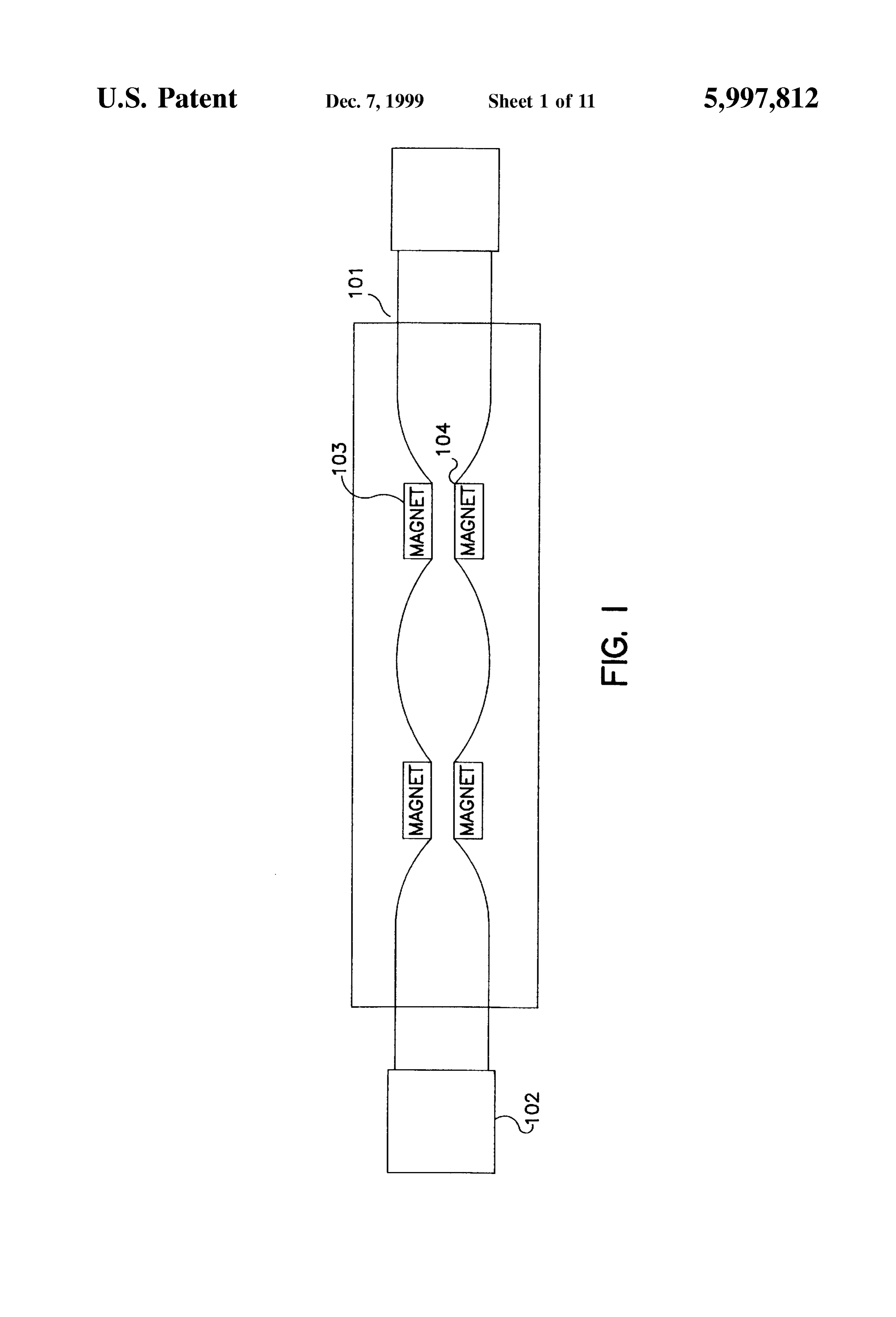
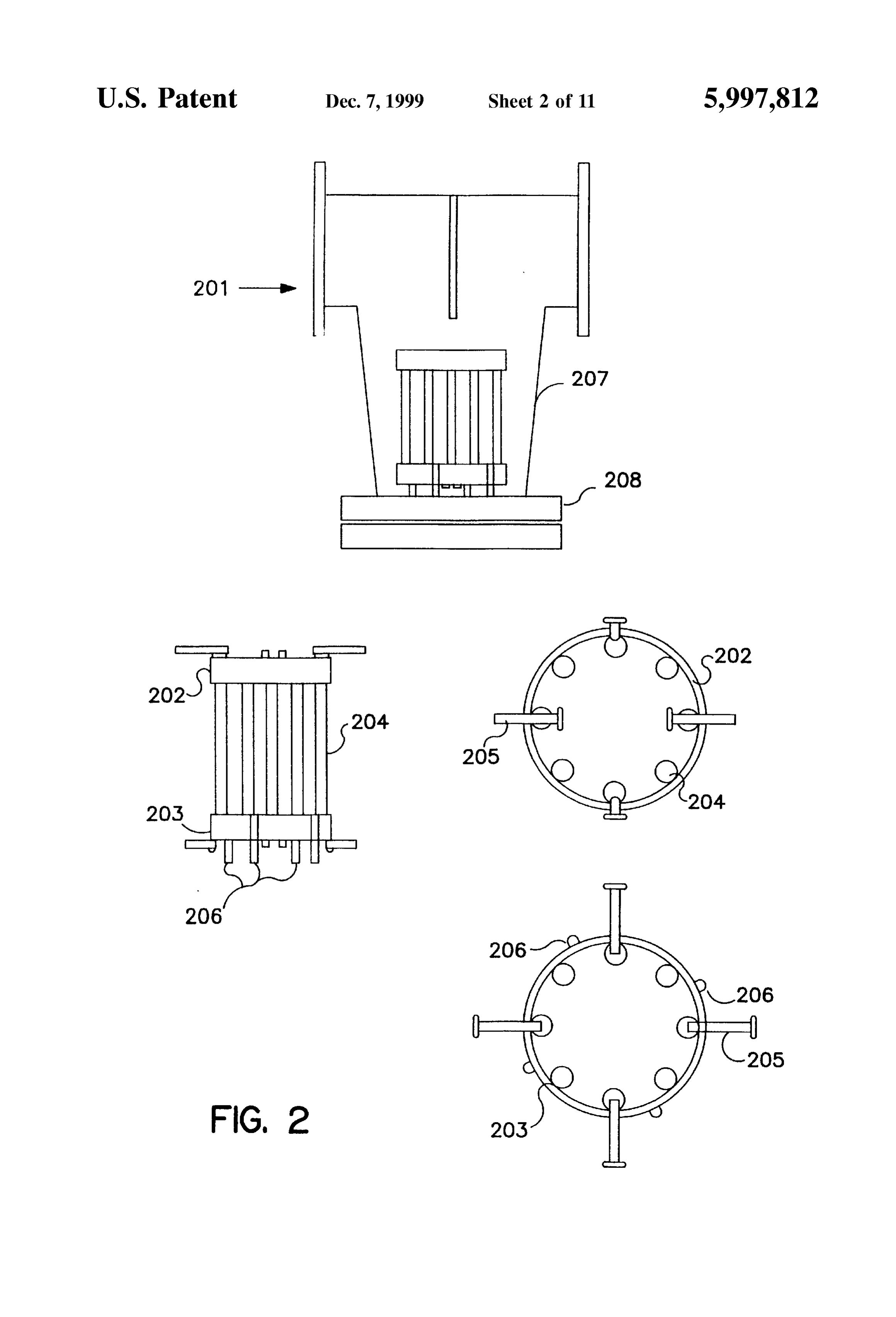
increase the hydrophobicity of the fluid and can be main tained for a period of time Sufficient to allow for Subsequent DESCRIPTION OF THE DRAWINGS manipulations Such as filtration. Various components within the fluid, Such as hydrophobic oils in a coolant liquid, can be FIG. 1 Placement of magnets along a fluid flow. efficiently removed by taking advantage of the increased FIG. 2 Magnet schematic.
hydrophobicity, fragmentation and increased length of FIG. 3 Oxidant/magnetic/UV system. treated molecules. Treated fluid can also be further subjected 15 FIG. 4 Schematic of coolant fluid disinfection unit. to a disinfecting amount of ultraViolet radiation or biocide.
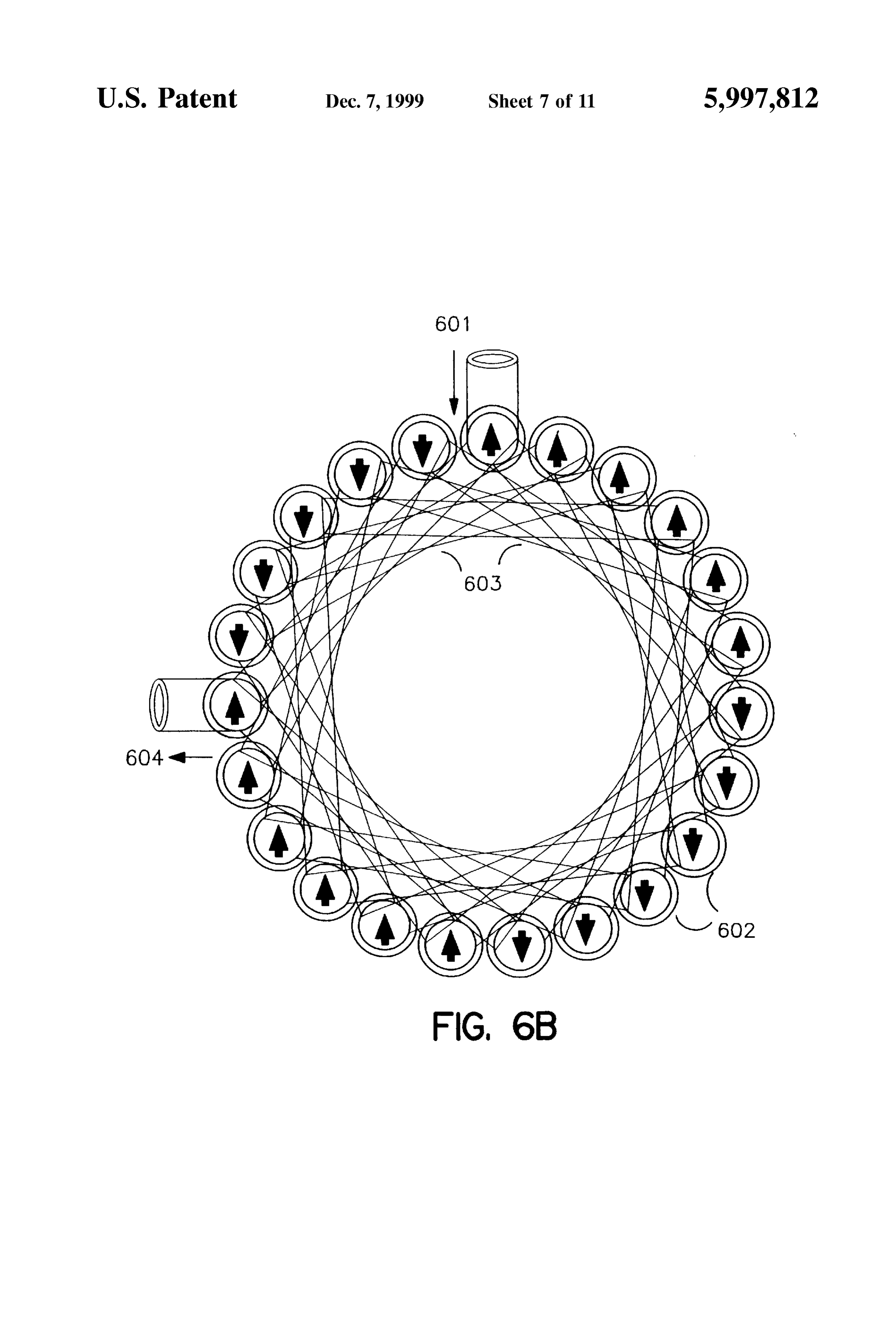
Another embodiment of the invention is directed to fluids FIG. 5 Iron Separation and Scale reduction Scheme. treated according to the methods of the invention. These FIG. 6 Rigid tubing for model unit shown in (A) longi fluids may be industrial fluids Such as coolants and washing tudinal and (B) cross-section.
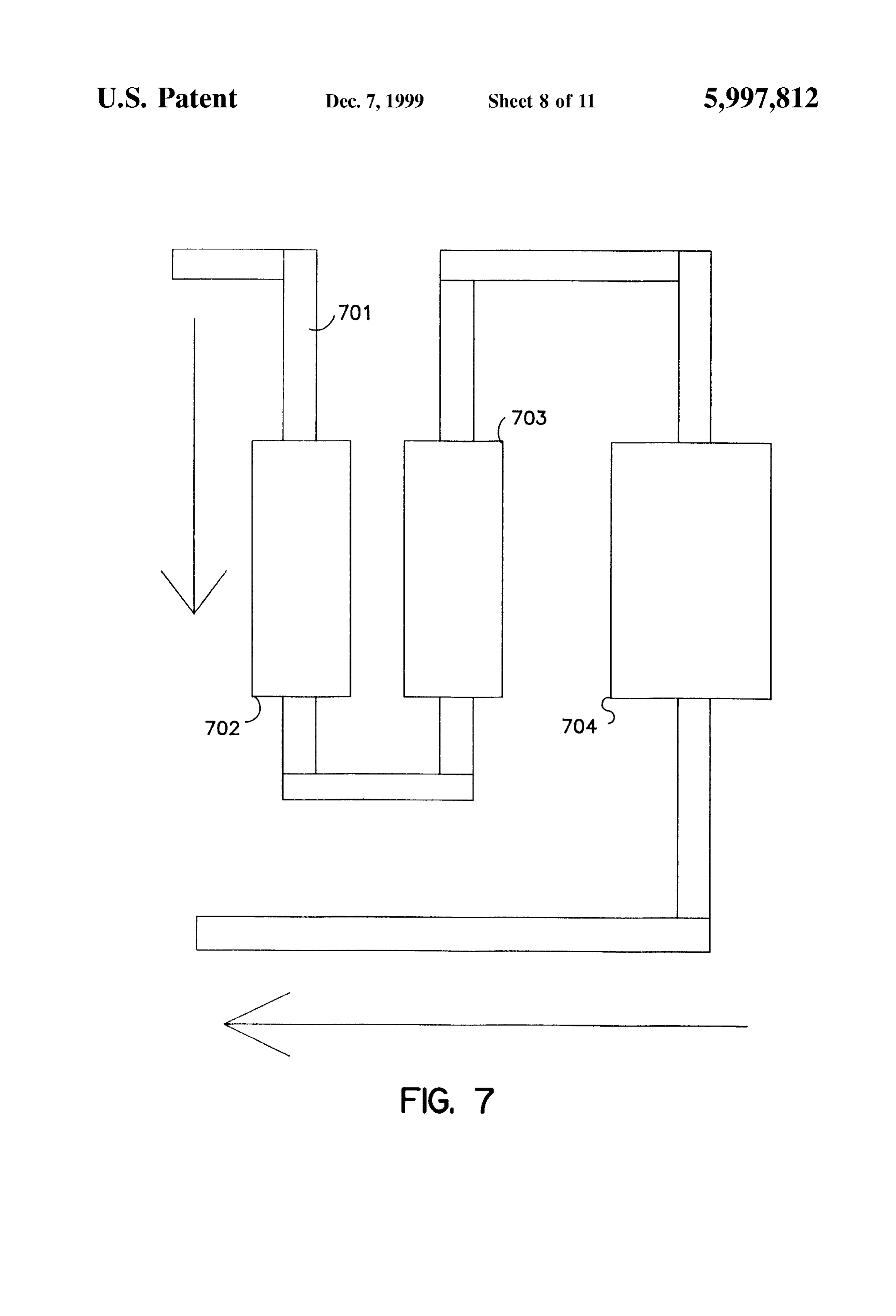
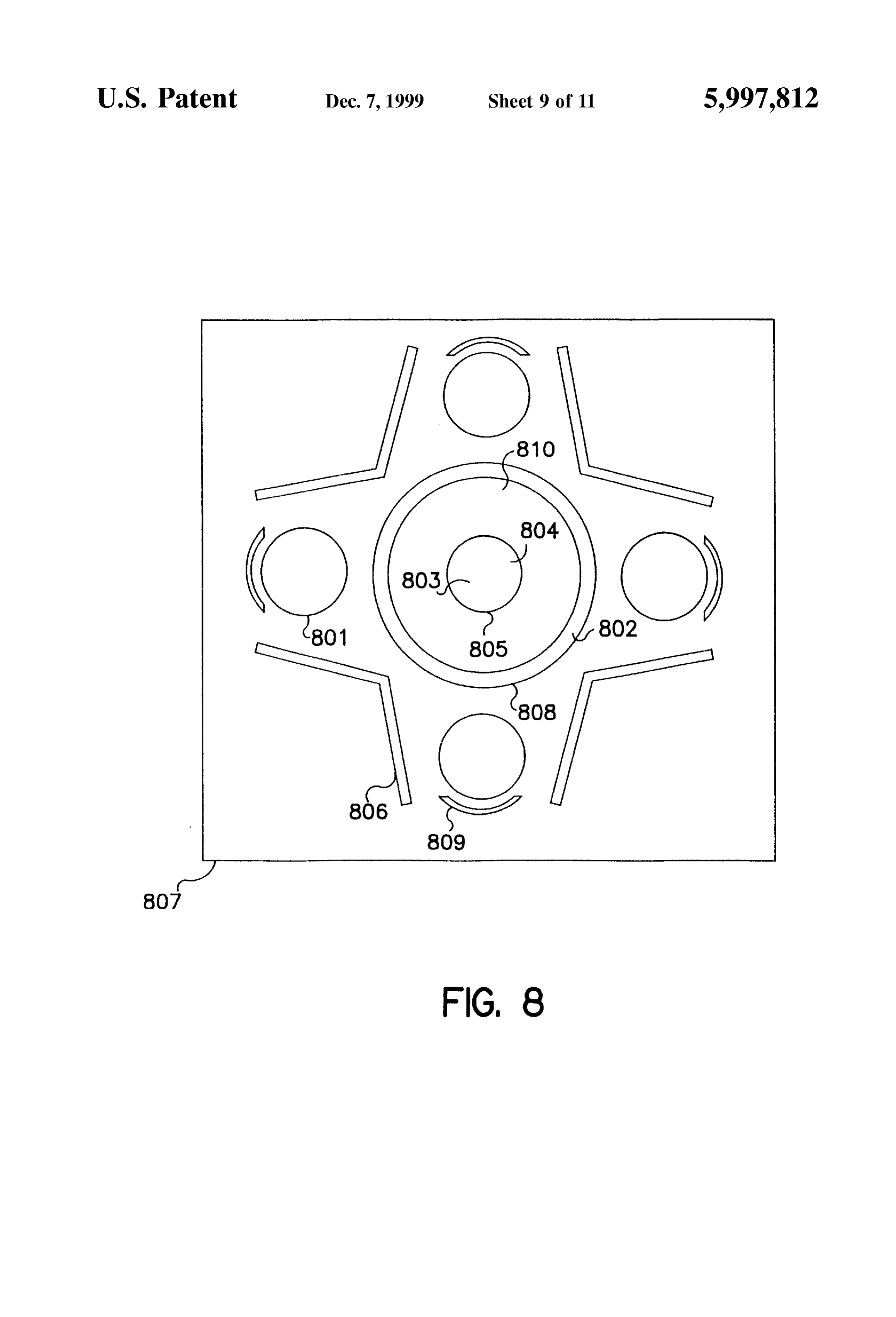
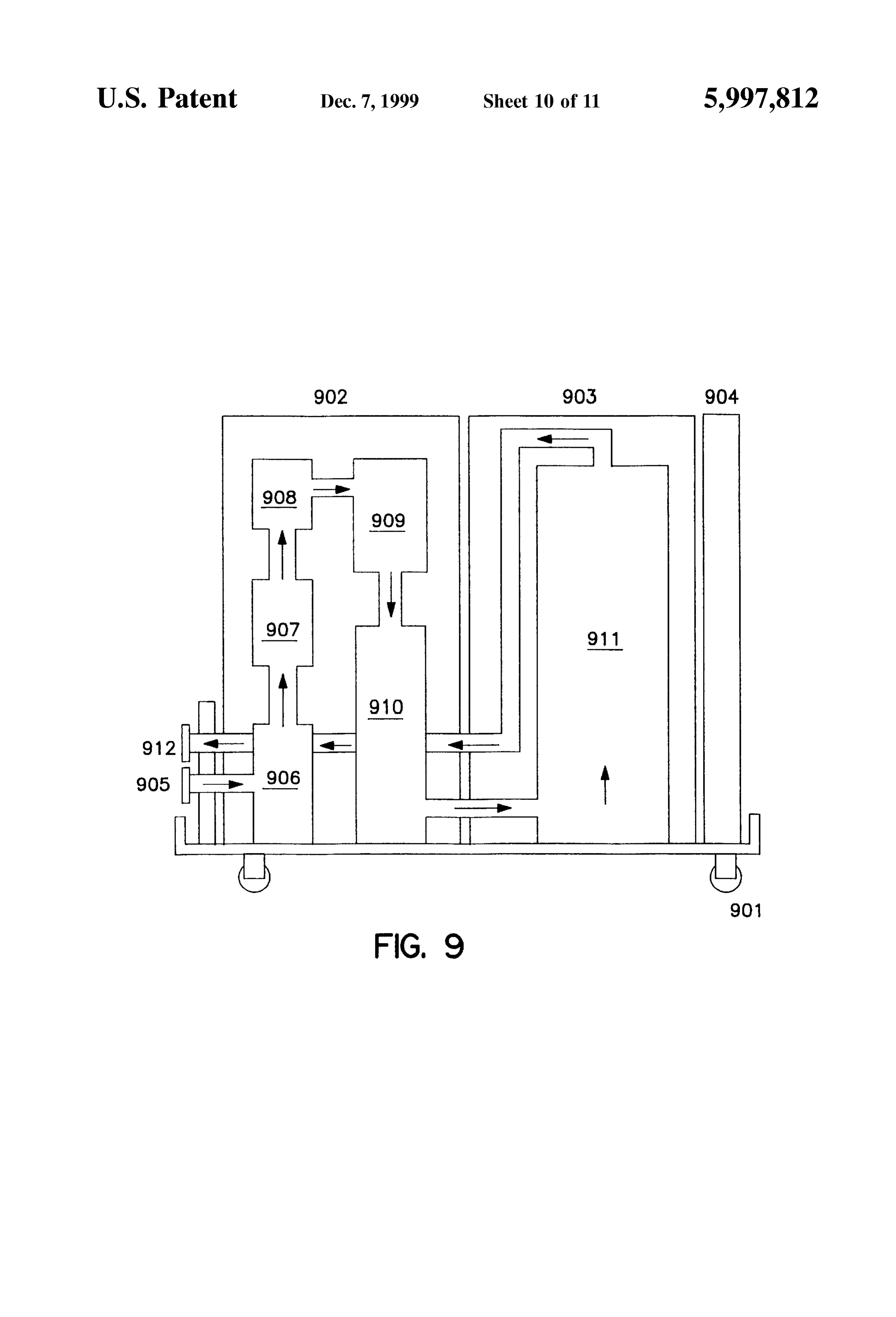
Solutions, petrochemicals Such as natural gas, gasoline or FIG. 7 Oil separation scheme. diesel fuel, or water Supplies obtained from lakes or rivers. FIG. 8 Cross section of fluid pipe and Surrounding UV Further, fluids, Such as potable water, may be disinfected to System.
a desired level of contamination or completely Sterilized. FIG. 9 A model filtration/germicidal system. The level of microorganisms that remain after treatment can
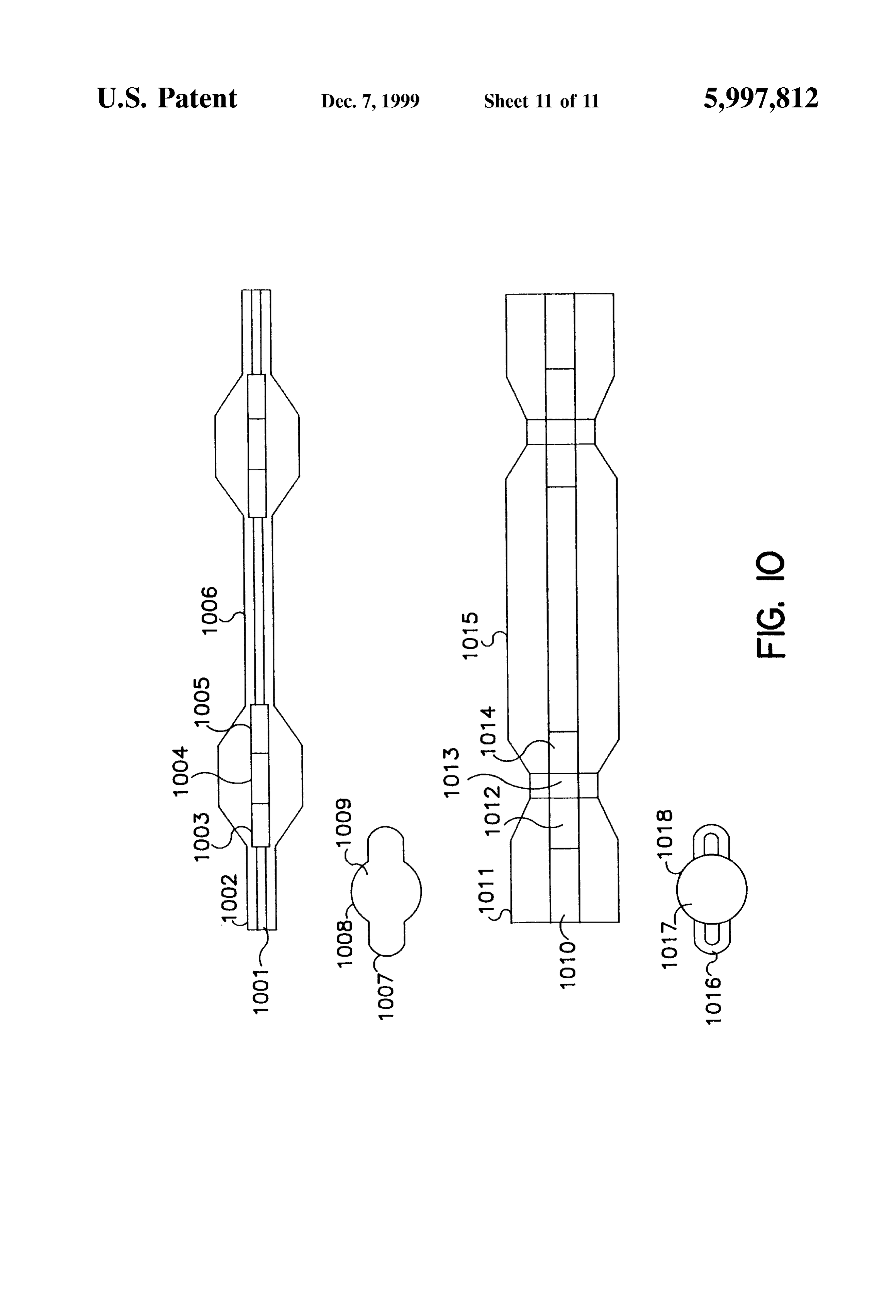
FIG. 10 Tubing structure in both longitudinal and cross be maintained at levels acceptable to local, State or federal 25 Section
Standards. showing periodic shape modifications for generating turbulence.
Another embodiment of the invention is directed to appa ratus for disinfecting a contaminated fluid. The apparatus DESCRIPTION OF THE INVENTION comprises a tubing System for guiding the passage of the fluid through the apparatus wherein a portion of the tubing As embodied and broadly described herein, the present has ultraViolet-transmissible walls. The apparatus further invention is directed to novel methods and apparatus for comprises a contaminant Separation System comprising a exposing a fluid to applied fields and to fluids treated high-gauss magnet that may be an electromagnet or a according to these methods.
permanent magnet. The apparatus also comprises an ultra Fluids used in industrial and other Settings are typically Violet radiation System for irradiating the contaminated 35 either aqueous or organic. Organic fluids include, for fluid. The UV radiation system comprises a plurality of example, processing and washing fluids, purified or Semi ultraViolet lamps in close proximity to the portion of purified chemicals. Such as alcohols and acids, paints, ultraViolet-transmissible tubing carrying the contaminated fertilizers, lubricants and other oils, fuels. Such as diesel, fluid. gasoline and other hydrocarbon-containing fluids, and all Another embodiment of the invention is directed to appa 40 forms of petrochemicals. Aqueous fluids include machine ratus for the magnetic treatment of a fluid comprising a tool coolants, process-washing fluids, cooling tower water, tubing System for guiding the fluid through the apparatus, a juices and other drinks for bottling, and water Supplies magnetic filter for removing ferrous and ferric complexes prepared for discharge or to be made potable. In all of these from the fluid, and a high-gauSS magnet positioned So as to fluids, contamination due to microbial growth and leakage generate a magnetic field within the fluid. Magnetic treat 45 from other Systems is a critical and constant problem. ment increases the hydrophobicity of contaminants within In an industrial Setting, for example, metal particles and the fluid allowing for efficient removal. way oils heavily contaminate coolants in assembly and Another embodiment of the invention is directed to appa manufacturing lines. In a packing plant, fruit juices, Soft ratus for producing a Supply of potable water. An apparatus drinks, beers including lower alcohol beers, and other bev comprises a tubing System, an inlet for a water Supply and 50 erages become contaminated with microorganisms. Such as an outlet for potable water, a magnetic filter, a high gauSS bacteria and yeast or other types of fungi. Other contami magnetic and an ultraViolet radiation treatment System. nants enter these fluids as they proceed through various Water enters the apparatus through an inlet port and into the mixing and bottling Systems. These and other contaminants tubing System which guides the water through the apparatus. Serve as an abundant nutrient base in which microorganisms The magnetic filter is positioned downstream of the inlet 55 flourish.
port and removes ferrous and ferric complexes from the Conventional methods for the disinfection of fluids water Supply. One or more magnets may be positioned include methods for the removal and/or Selective destruction downstream of the filter to Subject the water to a high-gauSS of microorganisms. In filtration, microbial contaminants are magnetic field. Another filter may be positioned downstream removed using, for example, Selectively permeable mem of the magnet to collect additional contaminants made 60 branes. These membranes are placed in the fluid flow and Separable by the magnetic treatment. Finally, the decontami Selectively absorb or filter contaminants of a particular size nation System treats the water with a disinfecting amount of or molecular weight. Although useful, these methods cannot ultraViolet radiation and makes the water Suitable for human be applied to all fluids and, often, it is not possible to consumption. Further, the System may be electronically Selectively remove the contaminants without removing a coupled with a diagnostic device capable of detecting infec 65 significant portion of the fluid itself. Further, filtration sys tious and potentially harmful microorganisms in the fluid. tems are impractical for the disinfection of many types of This device may be further linked with a means for con industrial fluids. For example, certain fluids contain com
Page 17
ponents essential to their function that would be filtered out gativity as it passes through the magnetic field as water along with any unwanted contaminants. Others, Such as molecules line up in response to the magnetic field. AS a fluids with high Viscosities, require multiple filtration Steps consequence, hydrophobic contaminants can be more easily and multiple filter changes making the filtration proceSS and more effectively Separated from the fluid using, for impractical. example, conventional Systems based on hydrophobic/ Another conventional method for the disinfection of fluids hydrophilic Separation.
is to add toxic chemicals, antibiotics or other biocidal Further, magnetic treated flowing fluid increases in elec Substances to kill and/or inhibit proliferating microorgan tronegativity isms. These methods, although useful in the short term, effect, termedastheit Lorentzpasses through the magnetic field. This provide few long term benefits and pose Serious problems of field strength verses fluid force, is a function of magnetic velocity. The greater the field their own. The use of toxins, antibiotics or other chemicals strength or the velocity of the fluid flow, the greater the to inhibit microbial growth in a fluid presents health risks to electronegativity of the fluid. Hydrophobic workers, as well as to the environment, and can impair the in particular organic Substances, become leSSSubstances Soluble and, due to function or utility of the fluid. Other methods such as this increased eletronegativity.
exposure to ultraviolet (UV) radiation, useful for UV trans 15 Further Still, magnetic treatment can impart a magnetic parent fluids, have proven to be ineffective for non-UV transparent (opacque) fluids. Further, these methods typically charge to contaminants within the fluid. Such contaminants require passage of the entire Volume of fluid through a can be Segregated from the fluid and removed. Contaminants thin-film. Such complications make the process prohibi that become charged include magnetic particles Such as iron tively costly and Sometimes impossible to perform on a large that had been demagnetized by high temperatures Such as volume of fluid. Newer methods to control microbial growth encountered in many industrial processes. These particles, include pasteurization which, effective in many Settings, can although previously magnetic, can loose their magnetism damage the molecular structure of the fluid and tends to within after heating. High temperatures reorient magnetic domains require large amounts of energy in constant temperature particles. By exposing demagnetized particles to a cycling. Further, many of the components in a fluid Such as, 25 magnetic field, magnetic domains re-establish and the par for example, a machine tool coolant, would be altered during ticles again become magnetic. AS Such, the newly magnetic repeated pasteurization Steps and thereby have a reduced particles Self-aggregate and can be collected using conven efficacy. tional magnetic or other filtration devices that are well It has been discovered that contaminated fluid can be known to those of ordinary skill in the art. disinfected by the magnetic treatment of the fluid coupled All or any combination of these factors can be utilized to with exposing the fluid to disinfecting amounts of ultraViolet encourage the Separation of hydrophobic and other contami radiation. Magnetic treatment alters the molecular structure nants from a fluid. Magnetic effects can last between leSS of contaminants within the fluid allowing for their efficient than one Second to as long as about four Seconds, more than Separation and removal. In this manner, microbial contami a Sufficient period to conduct a separation Step Such as, for nation of fluids, including UV-opaque fluids Such as indus 35 example, filtration. However, there are also long term effects trial fluids as well as UV-transparent fluids such as water and of magnetic treatment. For example, magnetic treatment other water-based fluids, can be Substantially reduced or fractures and/or denatures Side chains of long chain mol eliminated. Substantially reduced means that microbial con ecules. These molecular fragments can be easily Separated tamination is reduced Such that useful life of the fluid is from the fluid. Contaminant molecules So modified are also extended, the fluid is sufficiently disinfected to be usable for 40 less likely to cause filming and occlusion over UV trans a desired property or the need for other microbial control missible Surfaces.
methods Such as, for example, biocides or pasteurization, is Magnetic treatment can also be used to activate dormant lowered. microorganisms in a fluid. Although UV treatment will kill It has also been discovered that maximum UV radiation active or vegetative microorganisms in a fluid, Spores, cysts transmission to a fluid flow can be maintained by establish 45 and other inactive microorganisms are very resistant to ing a flow rate Sufficient to prevent occlusion based on the conventional microbial-control technologies and will remain level of contaminants in the fluid, or by removing a mini viable in the fluid and over time will proliferate. Passage of mum percentage of contaminants from a Set flow rate to the fluid through a magnetic field causes Spores to germinate maintain maximum transmission of UV radiation. Using and cells to transition out of a resting Stage. These activated various combinations of these techniques, almost any fluid 50 microorganisms are significantly more Susceptible to ultra can be disinfected and at a cost which is Substantially violet radiation and can be killed. Killing of activated cells reduced as compared to conventional techniques. occurs with a reduced level of radiation exposure requiring One embodiment of the invention is directed to a method reduced energy and expense as compared to that necessary for the disinfection of a fluid by passing the fluid through a without treatment. This is in direct contrast to prior methods magnetic field and Subjecting that fluid to a disinfecting 55 that, using magnetic treatment attempted to kill Such micro amount of ultraviolet radiation. Magnetic treatment of fluid organisms as described in U.S. Pat. Nos. 5,248,437 and has multiple advantages both immediate and long term. 4,065,386.
First, in response to magnetic treatment, hydrophobic Sub Activation, which includes germination, is the process of stances within a fluid become more hydrophobic and, converting a dormant cell into a vegetative cell. Activation, therefore, leSS Soluble in a hydrophilic environment. Long 60 as known to those of ordinary skill, can be spontaneous, but chain molecules Such as, for example, chains of greater than can also be induced by a traumatic event (e.g. pH change, about 4 carbon or Silicon atoms, become extended in heat, Sulfhydryl compound) or a germinating agent (e.g. response to a magnetic flux or field, altering bond angles alanine, dipicolinate, Mn"). Passage through a magnetic between atoms and thereby lengthening the molecule's field can Substitute for that event or agent and thereby induce longitudinal dimension. This effect, termed the Delong 65 activation. Dormant microorganisms include, for example, effect, makes these molecules less water Soluble. In addition, Spores, eggs, ova, cysts and other dormant cells. Magnet the fluid becomes more polar, increasing overall electrone treatment for inducing activation of dormant cells in a fluid
Page 18
involves Subjecting the fluid to a magnetic field of between the extent of the field Strength for each magnet So as to about 2,000 to about 8,000 gauss, preferably between about provide optimal exposure of the fluid to the magnetic field. 3,000 to about 7,000 gauss, and more preferably between In those embodiments where magnets are Submerged within about 4,000 to about 6,000 gauss. the fluid, it may be desirable to coat the magnets with a In another embodiment, activation of dormant microor material to prevent damage to the magnet without interfering ganisms in a fluid can be induced by imparting an electro with either transmission of the magnetic field into the fluid static field or electric current to the fluid. The electric field or causing undesirable chemical reactions with the fluid or current required for activation, which may be either components. Such materials include, for example, Synthetic alternating or direct, can be generated by contacting positive polymerS Such as plastics and other non-conductive and and negative electrodes to the fluid. Electrodes may be relatively non-reactive materials.
placed upstream-positive and downstream-negative or The magnetic field strength of the magnet Should gener upstream-negative and downstream-positive. Field Strengths ally be at least about 500 gauss. Depending on the fluid and required for this proceSS are generally greater than about the amount and type of contaminants and other Substances 2,000 gauSS, preferably greater than about 3,000 gauSS, and within that fluid, field strength may vary from about 1,000 more preferably greater than about 4,000 gauSS. 15 gauSS to about 2,500 gauSS, from about 2,000 gauSS to about Magnetic treatment, as known to those of ordinary skill in 5,000 gauss, from about 4,000 gauss to about 6,000 gauss, the art, also reduces Scaling and corrosion of all Surfaces from about 6,000 gauss to about 8,000 gauss, or from about exposed to the fluid (J. D. Donaldson, Tube International, 7,000 gauss to about 9,000 gauss, or up to 10,000 gauss or Scale Prevention and Descaling, pp.39-49, January 1988). more. The range of Strengths useful for most applications is These effects include changes in particle size, crystallinity, within about 600 to about 9,000 gauss. The magnetic field crystal phase and morphology, rate of nucleation and Solu may be generated from an electromagnet or permanent bility. For example, increased magnetic Strength was found magnet, as desired. One advantage to electromagnets is that to increase particle size of calcium Sulphate (S. M. Grimes, field Strength can be varied during operation. This can have Tube International, Magnetic Effect on Crystals, pp. Significant advantages when a Single apparatus is used to 111-118, March 1988). These particles also showed 25 disinfect a variety of different fluids requiring different field increased aggregation with increases in magnetic treatment. Strengths for optimal operation.
Studies with Zinc phosphate showed that particle size also One example of Such a magnet is depicted in FIG. 2 in decreased in response to an increasing magnetic field. In which magnet unit 201 is shown in transparent croSS addition to changes in crystallinity, magnetic treatment can Section. In the Side View, top ring 202 is connected to bottom alter the morphology of crystals on various planes. Factors ring 203 by a series of transverse mounted magnets 204. that can influence these events include the nature of the fluid, Long bolts 205 secure top ring 202 to housing 207, and a the magnitude of the applied current, the pH of the fluid, the plurality of legs 206 are attached to bottom ring 203. The fluid flow rate, the fluid conductivity, the presence or magnet unit, housed in housing 207, can be fitted to connect absence of impurities and other chemicals Such as, for with a portion of the tubing System containing the fluid example, iron and the rare earth metals, and the concentra 35 through connector 208 which is specifically designed and tion of the various components within the fluid. These composed So as to allow for an unobstructed transmission of advantages and others are described in U.S. Pat. Nos. the magnetic field into the fluid.
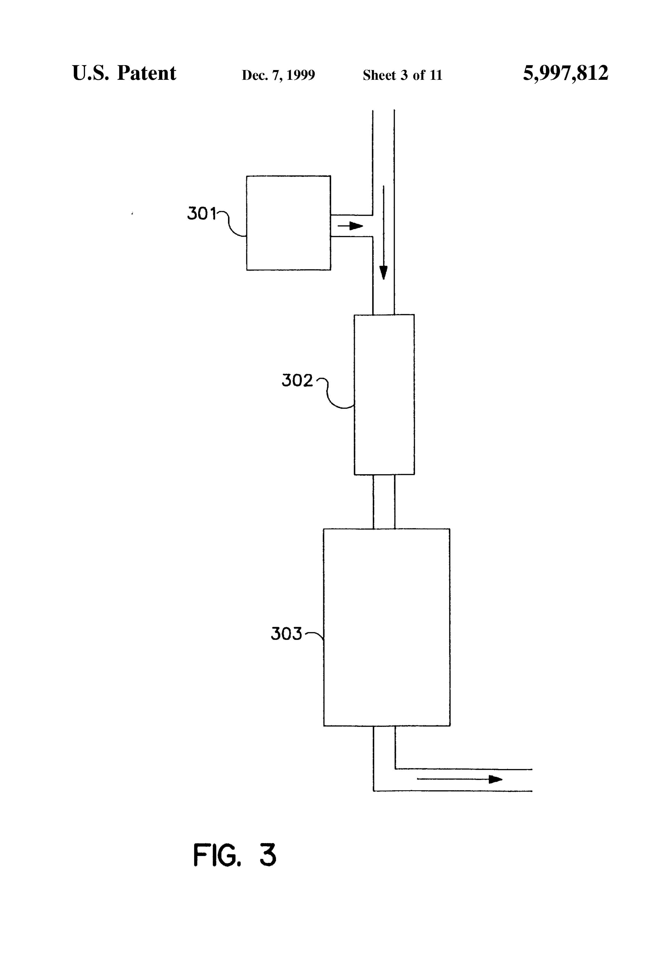
4,716,024; 4,568,901; 4,538,582; 4,519,919; 4,469,076; Disinfection by the System can be enhanced by adding 4,460,516; 4,428,837; 4,414,951; 4,381,754; 4,372,852; oxygenating agents and/or oxygen radicals to the fluid. AS 4,026,805 and 3,060,339. 40 known to those of ordinary skill in the art, oxygen radicals Methods and apparatus for the removal of iron, Such as can kill cells and other microorganisms by oxidizing Surface ferrous and ferric complexes, in a UV or other disinfection components and essential or key biomolecules of the System are preferred embodiments of the invention. microbe. A typical system is depicted in FIG. 3 wherein one Removal of iron-containing complexes by passing the fluid or more oxygenating agents. Such as OZone, hydrogen through a magnetic field reduces the potential of the fluid for 45 peroxide, iron oxides or iron hydroxides (e.g. ferrates) are forming iron-containing deposits on the Surface of UV added to the apparatus at section 301. Oxygenated fluid transmissible Surfaces which block significant amounts of travels downstream past magnet 302 to UV disinfection UV radiation. Removal also improves disinfection with UV system 303, disinfecting the fluid along the way. The system radiation, reduces the corrosive potential of the fluid and can also be designed to Supplement the fluid with ferrous or increases the value of the fluid itself. 50 ferric oxide, air or oxygen (gas or liquid) at Section 301. By For the magnetic treatment of water and other aqueous exposing the oxygen to UV radiation either from a UV fluids, a magnet is placed in close proximity to the fluid So system placed at section 301 or simply by allowing the as to generate a magnetic field within the fluid. The magnet downstream UV system 303 to form oxygen radicals, micro may be mounted externally to the fluid path or internally, organism killing can be enhanced.
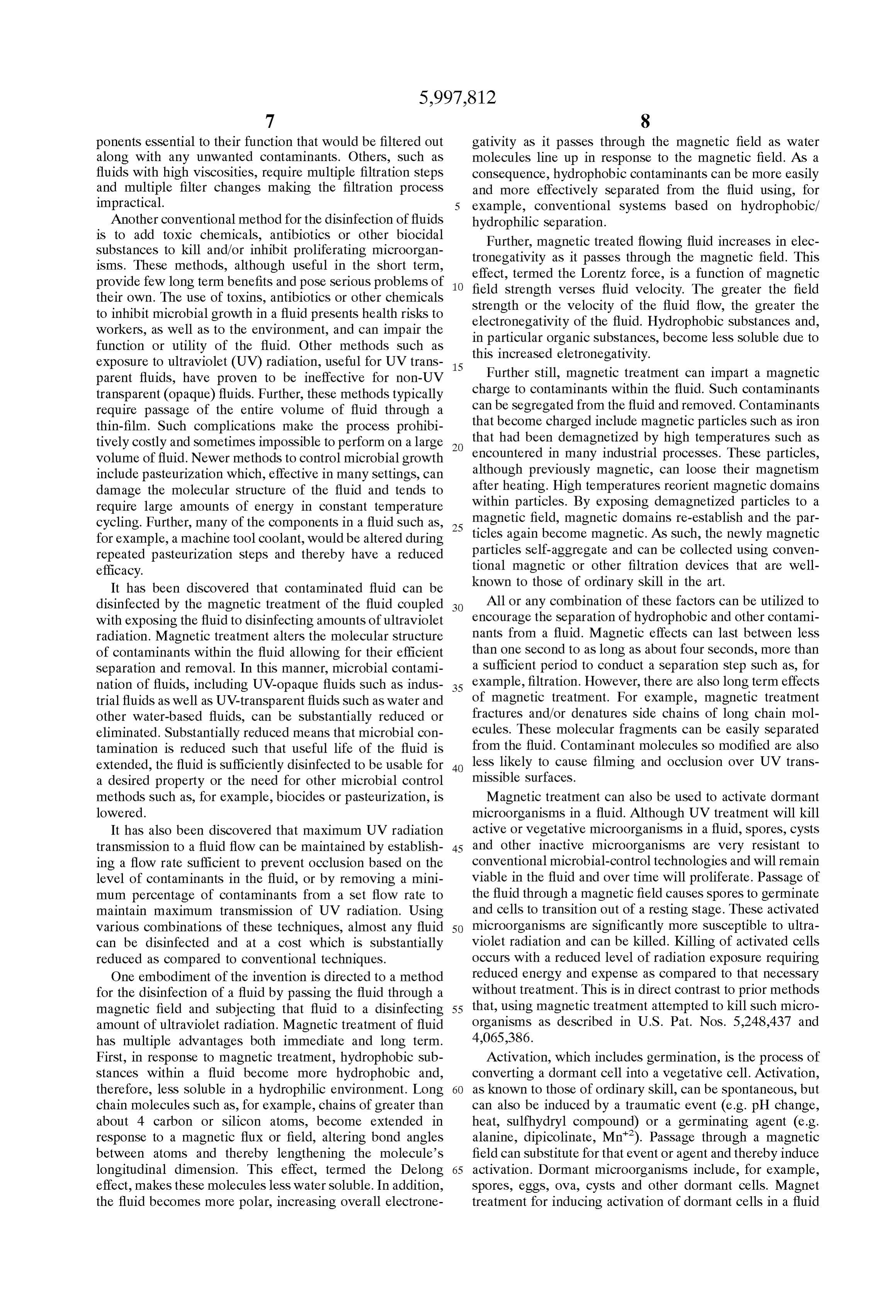
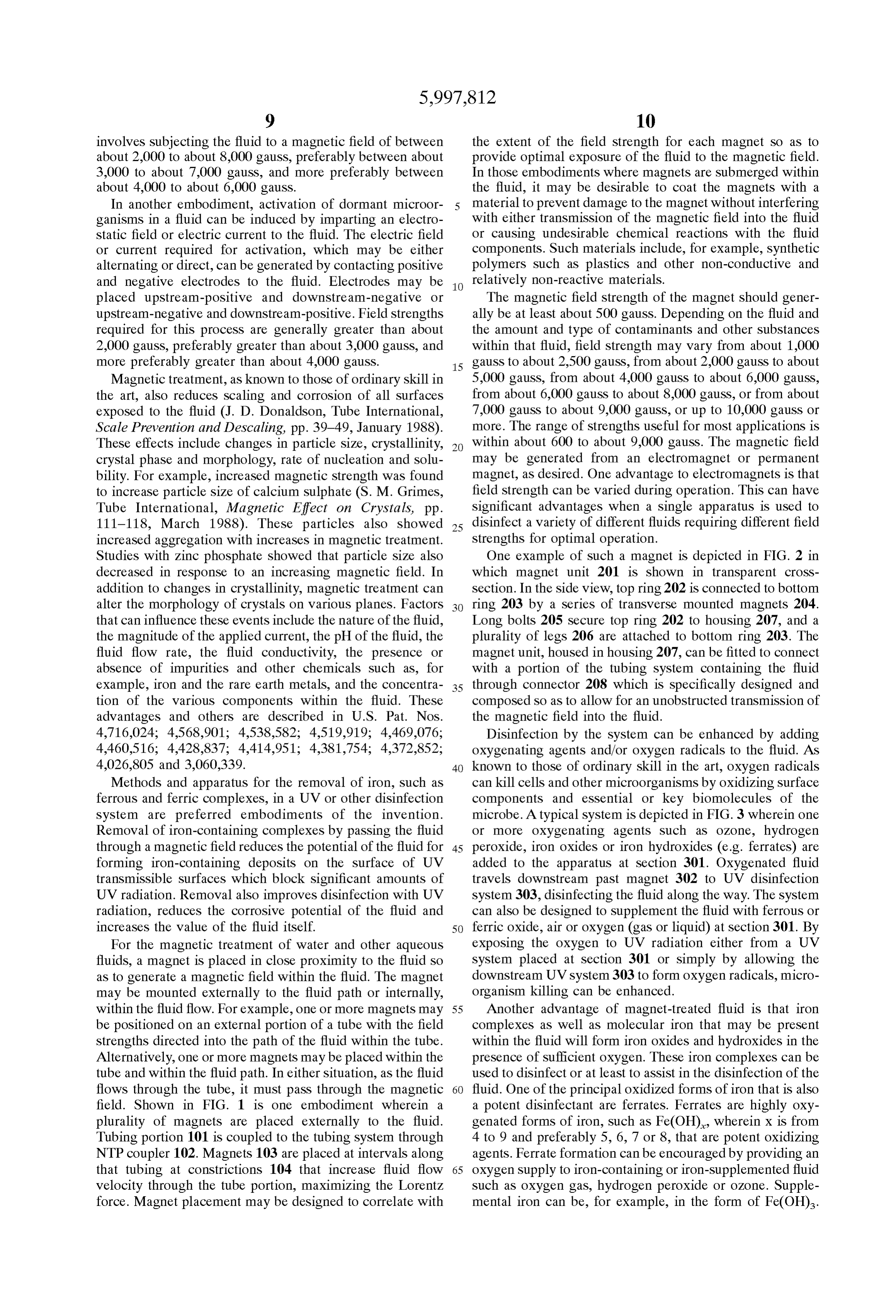
within the fluid flow. For example, one or more magnets may 55 Another advantage of magnet-treated fluid is that iron be positioned on an external portion of a tube with the field complexes as well as molecular iron that may be present strengths directed into the path of the fluid within the tube. within the fluid will form iron oxides and hydroxides in the Alternatively, one or more magnets may be placed within the presence of Sufficient oxygen. These iron complexes can be tube and within the fluid path. In either situation, as the fluid used to disinfect or at least to assist in the disinfection of the flows through the tube, it must pass through the magnetic 60 fluid. One of the principal oxidized forms of iron that is also field. Shown in FIG. 1 is one embodiment wherein a a potent disinfectant are ferrates. Ferrates are highly oxy plurality of magnets are placed externally to the fluid. genated forms of iron, Such as Fe(OH), wherein X is from Tubing portion 101 is coupled to the tubing system through 4 to 9 and preferably 5, 6, 7 or 8, that are potent oxidizing NTP coupler 102. Magnets 103 are placed at intervals along agents. Ferrate formation can be encouraged by providing an that tubing at constrictions 104 that increase fluid flow 65 oxygen Supply to iron-containing or iron-Supplemented fluid Velocity through the tube portion, maximizing the Lorentz Such as oxygen gas, hydrogen peroxide or OZone. Supple force. Magnet placement may be designed to correlate with mental iron can be, for example, in the form of Fe(OH).
Page 19
Other methods to oxygenate the fluid include adding air or desired FV. MPC is a variable which is dependant on the oxygen gas and exposing the fluid to ultraViolet radiation. Velocity of the fluid as it proceeds through the radiation UV radiation imparts energy to the oxygen molecules that treatment. The more rapid the rate of fluid flow, the less the encourage formation of oxygen radicals. Once formed, these amount of contaminants that need to be removed. The lower oxygen radicals can disinfect or at least enhance disinfection the flow rate, the greater the amount of contaminants that of the fluid. must be removed. AS flow rate can be controlled, the MPC Flow rate of the fluid through the magnetic field is can be determined for most any fluid.
dependant on the conductivity of the fluid. In large part, fluid flow rates are related to fluid conductivities. In general, the is aAlthough
Volume solid particles may be present in the fluid, MPC percentage, not a Weight percentage and particle flow velocity for organics would be about 10 times higher removal is not considered in the calculation. Consequently, than for water-based fluids due to the lower conductivity of MPC is a calculation of the volume of contaminants that organic fluids. Aqueous fluids tend to have a higher con must be removed from the fluid for Successful disinfection ductivity and can be treated at about 2 meters/second and by ultraviolet radiation in a flowing system. Nevertheless, fluid velocity through the field for most water-based systems with many types of fluids, particle removal may be required is expected to be from about 1 meter/second to about 5 15 as there can be a Synergistic effect of certain metallic meters/second, but may be more or less, as desired (e.g. from particles about 2 to about 5 feet per second or from about 10 to about most any with heavy oils that rapidly leads to occlusion of Surface. In Such cases only when both heavy oils 40 feet per Second). In fluids containing increased amounts and metallic particles are removed can occlusion be pre of dissolved solids, flow velocity through the magnetic field vented and radiation treatments or other disinfection mea may be decreased Such as, for example, to about 4 meterS/ Sures be Successfully administered.
Second, about 3 meters/second, about 2 meters/second or less than about 1 meter/second. In fluids containing reduced Fluids that can be disinfected according to the invention amounts of dissolved Solids, flow velocity may be increased. include, for example, liquids Such as water Supplies used in Petroleum products Such as natural gas, gasoline and fuel oil the preparation of potable water, carbonated beverages and have a lower conductivity and require higher flow rates of 25 other fluids under pressure, flavored drinks, fruit juices, Soft from about 5 meterS/Second to about 12 meterS/Second, and drinks, beers, wines and other Such liquids. In all of these preferably from about 10 meters/second to about 15 meters/ examples, water Supplies are necessary for creation of the Second, but can include flow Speeds of from about 14 product and that water as well as the resulting product passes meters/second to about 20 meters/second or higher. through a maze of machinery for manufacture and bottling Fluid flow paths can be modified to maximize exposure to of the particular drink. Throughout the process, microbial the magnetic field. Constrictions can be placed along the asSociated withisthea constant contamination problem as well as problems tubing to place one or more magnetic fields within the fluid contaminant removal,machinery. magnetic By using a combination of treatment and exposure to path which have the added advantage of increasing or decreasing the Velocity of the fluid through the magnetic ultraviolet radiation, microbial contamination can be reduced to manageable levels and, if desired, completely field (e.g. FIG. 1). Temperatures at which the fluid is treated 35 eliminated.
will generally be between about 60° F to about 90°F, but can be lower or higher as desired. Lower temperatures may Additional fluids that can be treated include petroleum be required or useful for handling combustible or otherwise products and petrochemicals. Such as, for example, flammable fluids whereas higher temperatures may be more petrolatum, natural gas, gasoline including diesel fuel, kero useful for treating large Volumes of non-hazardous liquids 40 Sene and all forms of fuel for internal combustion engines, and other fluids. Further, fluid preSSures can also vary from ethylene, ammonia, Synthetic petrochemicals, fertilizers, ambient to high pressure systems with limits defined by the paraffin, naphthene, alcohols Such as methanol, ethanol and design of the apparatus treating the fluid. butanol, acids, and other like chemical compounds. In addition to magnetic treatment, fluid can also be Other fluids that can be treated according to the method of Subjected to ultrasound over a wide range of frequencies. 45 the invention are the industrial fluids. Industrial fluids Low frequency ultrasound of about 2 to about 40 watts or include fluids typically used in assembly lines and other about 50 Hz to about 100 KHZ can be used to supplement manufacturing configurations, to cool, clean and lubricate as magnetic treatment by placing a Sonicator either upstream or appropriate to the Specific operation being performed. Typi downstream of the magnet. Sonication enhances mixing and cal industrial fluids accumulate about 1% to 7% hydropho the killing effect of UV radiation. 50 bic hydrocarbon contaminants, with the remainder of con All of these processes can be further enhanced by estab taminants being Silicon oils and Soluble lubricants, all lishing a fluid flow rate sufficient to prevent fouling of UV usually in an aqueous medium (e.g. water). However, non transmissible Surfaces while maximizing transmission of aqueous fluids, Such as electrodischarge machine fluid ultraviolet radiation to the fluid. Transmission can be Sub (EDM), can also be successfully disinfected by the practice Stantially reduced by occlusion, caused by the contaminants 55 of this invention. Preferably, fluids to be disinfected are within the fluid, of Surfaces between the fluid and the Substantially opaque. Substantially opaque fluids are fluids radiation Source. Substantially means that UV transmission that do not allow lethal ultraViolet radiation energy to pass is reduced to a point rendering further treatments economi more than about 1.5 mm into the fluid. cally or practically unfeasible. Such occlusion can be pre In large factories, manufacturing lines can be quite long vented by establishing a fluid flow rate that prevents occlu 60 and contain huge Volumes of fluid Such as in the manufac Sion. That rate is dependent on the amount of contaminants ture of machinery, automobiles, aircraft and related parts. with the fluid. Consequently, in any fluid flow, a flow These lines comprise one or a plurality of machines in Series velocity (FV) can be set to prevent occlusion of contami (i.e. a working line), a fluid reservoir or tank, a plumbing nants over UV-transmissive surfaces within the system. System interconnecting the various machines and often a When flow velocity is fixed, above a set critical level of 65 fluid Sump with a pumping mechanism. The sizes of the contaminants, a minimum percentage of contaminants tubes that guide the flow of the fluids in Such system vary (MPC) can be removed from the fluid to achieve the set or tremendously depending on the location in the System
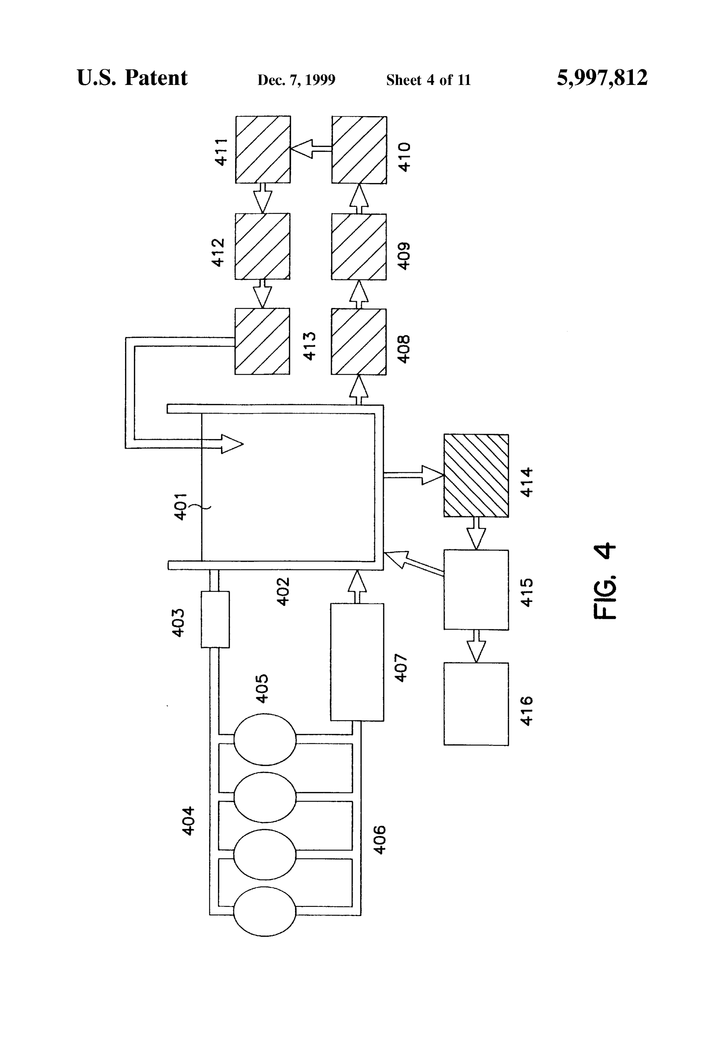
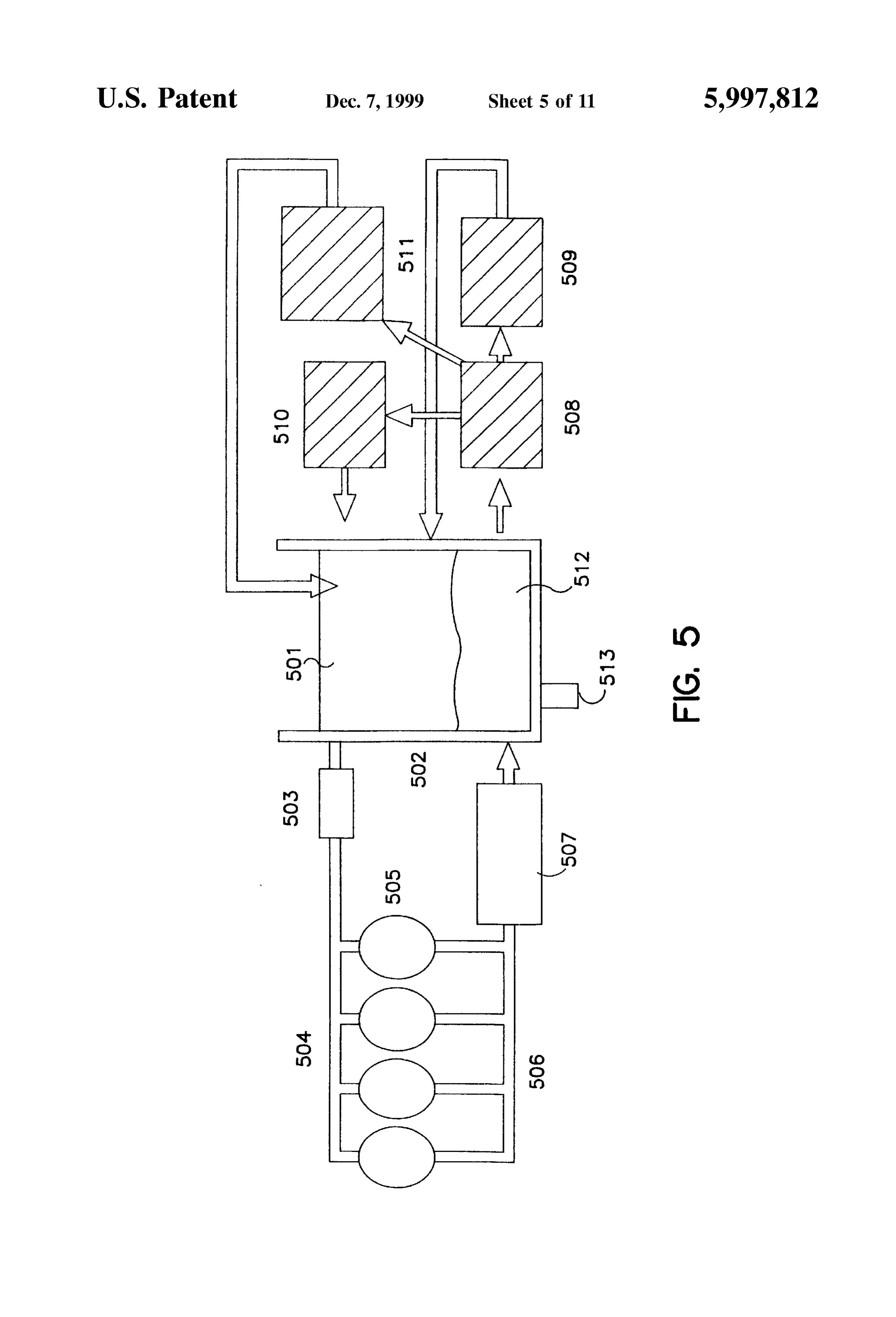
Page 20
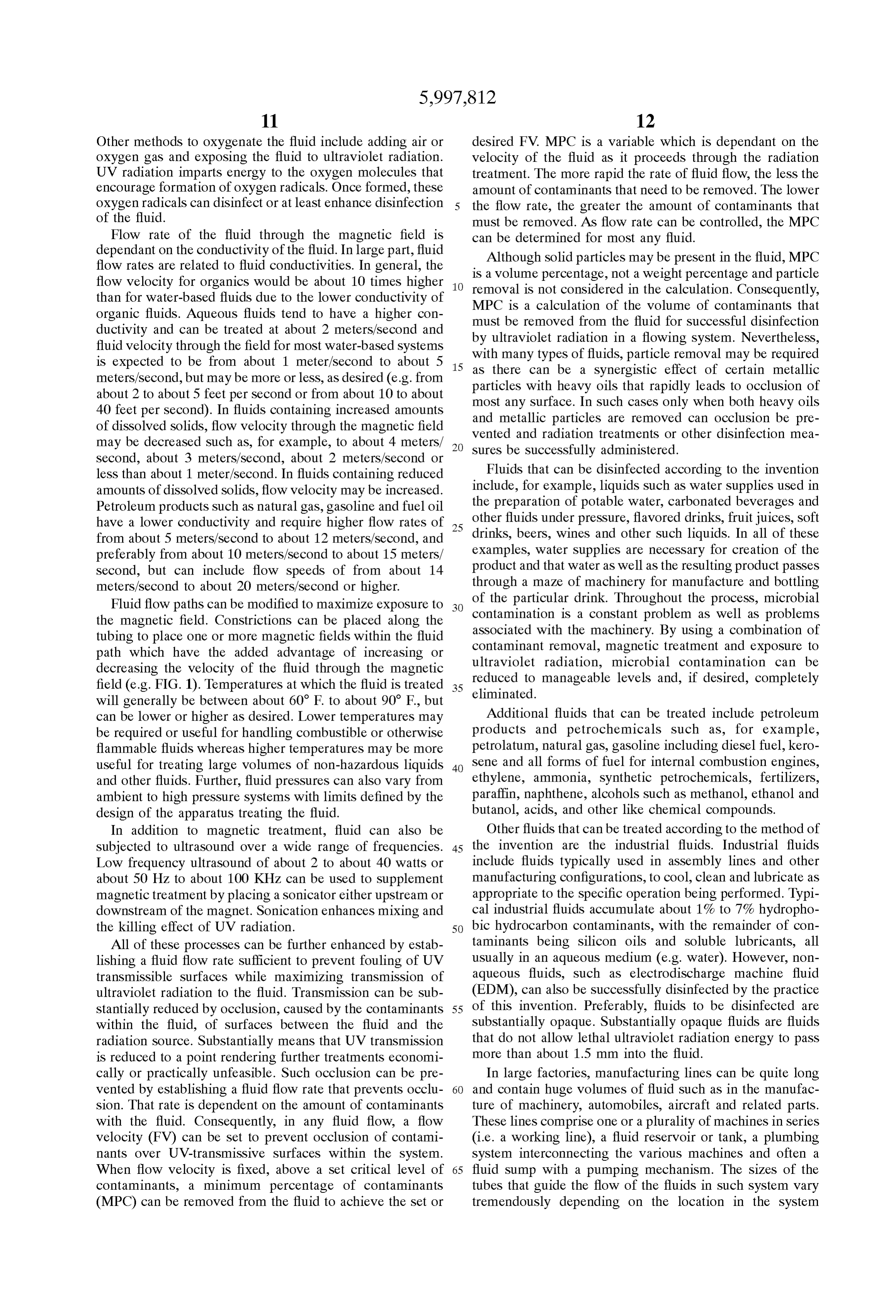
ranging from Small to large. A typical coolant disinfection plastic molding and forming coolants, quenching fluids, line is depicted in FIG. 4. As shown, coolant 401, starting recycled and recirculation fluids, and combinations thereof. from reservoir 402 which may be as large as 15,000 gallons In the disinfection of industrial fluids, one or more pre or more, travels in the direction of the arrows passing filters or particle filters are typically used to remove heavy through fluid pump 403, and to delivery system 404 which particles Such as metallic or plastic chips and filings. With supplies metal working machines 405. Returning from industrial coolants, this Step removes metallic particles manufacturing line through return System 406, coolant trav which, in combination with way oils, lead to sludge forma els to iron filter Screen 407 where residual iron and debris are tion and Subsequent occlusion of UV transmissible tubing or removed, and re-enters reservoir 402. Attached to reservoir UV lamps in the system. Prefilters are preferably comprised 402 is second fluid pump 408 which pumps fluid from of metal or plastic Strainers that remove the larger and reservoir 402 to an optional cyclonic separator 409 for coarser particles present in the fluid (e.g. metallic or plastic further contaminant oil removal and to iron magnetic particles, chips and shavings). Additional filters that can be Screener 410 which removes Soluble ferrous and ferric used include composite fiber-mesh filters and the like. Mesh complexes. Such as ferric hydroxides. From iron magnetic filters contain fibers of, for example, polyester, screener 410, coolant 401 flows through magnetic separator 15 polypropylene, nylon, Teflon, Nomex, Viscose or combina 411 where a high-strength magnetic field is applied. This tions of these materials. These fibers have a wide variety of magnetic field reduces the Solubility of organics within pore sizes (e.g. 1, 2, 5, 10, 15, 20, 25, 30, 35, 40, 45, 50, 75, coolant 401 by increasing fluid electronegativity, increasing 100, 125, 150, 175, 200, 300, 400, 500 micron) and are bond angles of long chain carbons and Silicons and fractur commercially available. Additionally, filters may contain ing Side chains of branched hydrocarbons and hydroSilicons. biological fibers comprised of, for example, peat and/or Oil separation is facilitated with long-term benefits that kenaf.
include reduced oil filming and fouling, reduced organic and Once larger particles have been removed, fluid flows to a inorganic Scale formation and reduced corrosion on all Second Stage filter Such as, for example, a coalescent filter to Surfaces of the tubing System. From iron magnetic Separator remove additional contaminants. Bag filters contain fibers, 411, coolant 401 travels to filter system 412 and to UV 25 Structured with various pore sizes, that are adherent to the disinfection system 413, which may include a turbulence contaminant. When placed in a fluid flow, bag filters capture generator, and back to reservoir 402. Optionally, first fluid those contaminants that cannot pass through the pores and pump 403 and/or second fluid pump 408 may be high contaminants that adhere to the fiberS. Coalescent filters, a Velocity pumps to pass coolant 401 through magnetic System Specific type of bag filter, are commercially available that are 416 and UV disinfection system 413 at a velocity sufficient adherent to the heavy way and hydraulic oils, Such as tramp to prevent UV lamp occlusion and to promote Scale reduc oils, common in industrial fluids. For industrial fluids, the tion throughout the system. From reservoir 402, coolant 401 combination of a particle filter and a separator, Such as an oil may also enter third fluid pump 414 to be pumped through Separator, removes Sufficient amounts of contaminant par centrifuge 415 where a percentage of contaminating oil is ticles and oils present in the fluid to allow for Successful removed before returning to reservoir 402. As the invention 35 disinfection with ultraViolet radiation. An important advan is not limited by the ability of UV radiation to penetrate a tage of this combination is that both live and dead bacteria fluid, most all fluids used in industrial Systems can be treated are removed from the fluid which thereby reduces the according to the methods of the invention. requirement for the ultraViolet System to conduct all of the A similar Scheme, Specifically designed to remove iron killing. AS dead bacteria are an important nutrient Source for and reduce scale formation is depicted in FIG. 5. As shown, 40 bacterial growth, removal of dead microbes is an important the various functions can be performed from the reservoir and previously unrecognized advantage. Additionally, because it is an advantage of the invention that the manu Smaller pore size filters, besides removing bacteria, can facturing line need not be interrupted when Servicing or remove parasites, eggs and cysts Such as, for example, maintaining the disinfection/Separation apparatus. In this Giardia, Cryptosporidium, Pseudomonads and Escherichia. embodiment, coolant 501 flows from reservoir 502 to pump 45 Thus, Smaller pore filters can facilitate the production of 503 whereby the coolant is pumped through delivery system potable water.
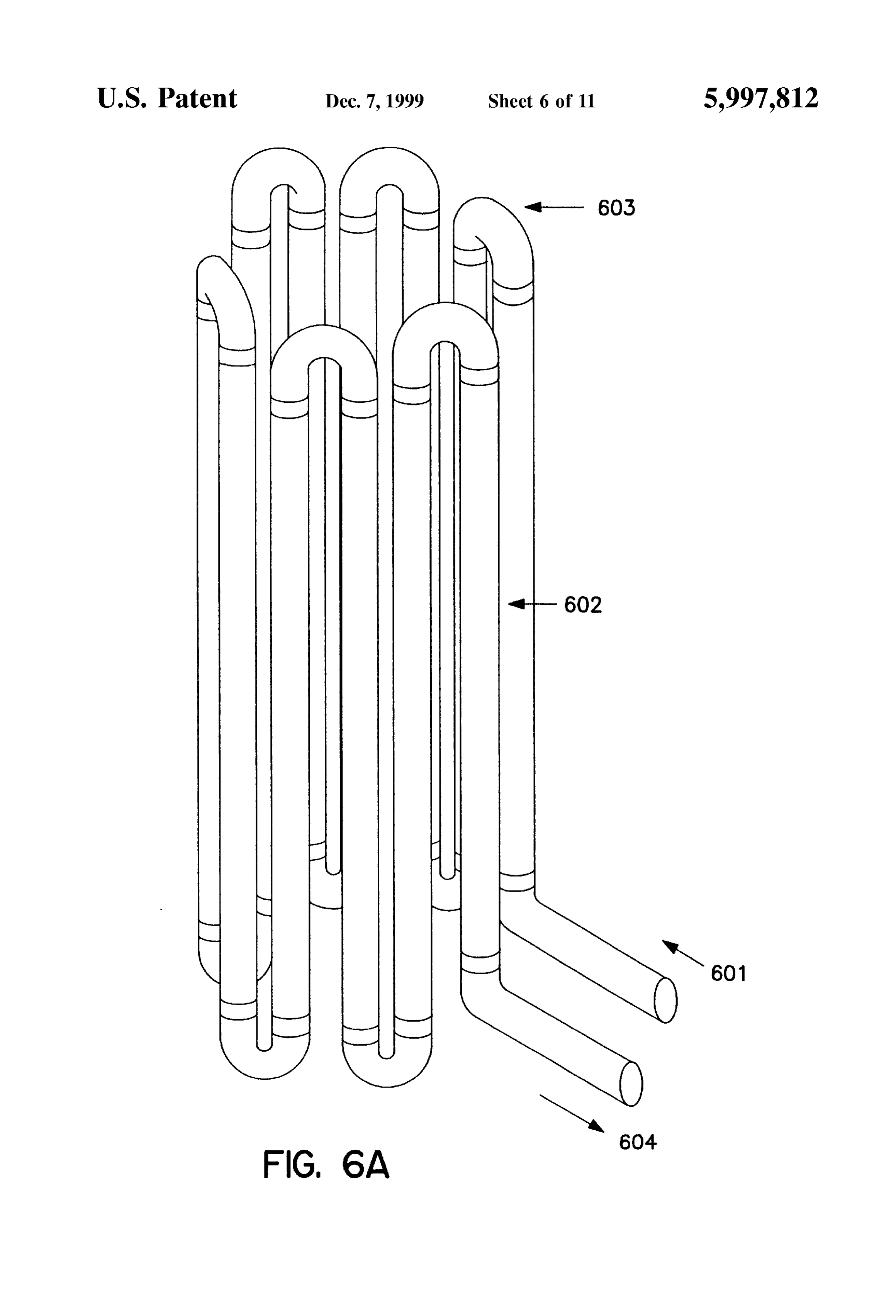
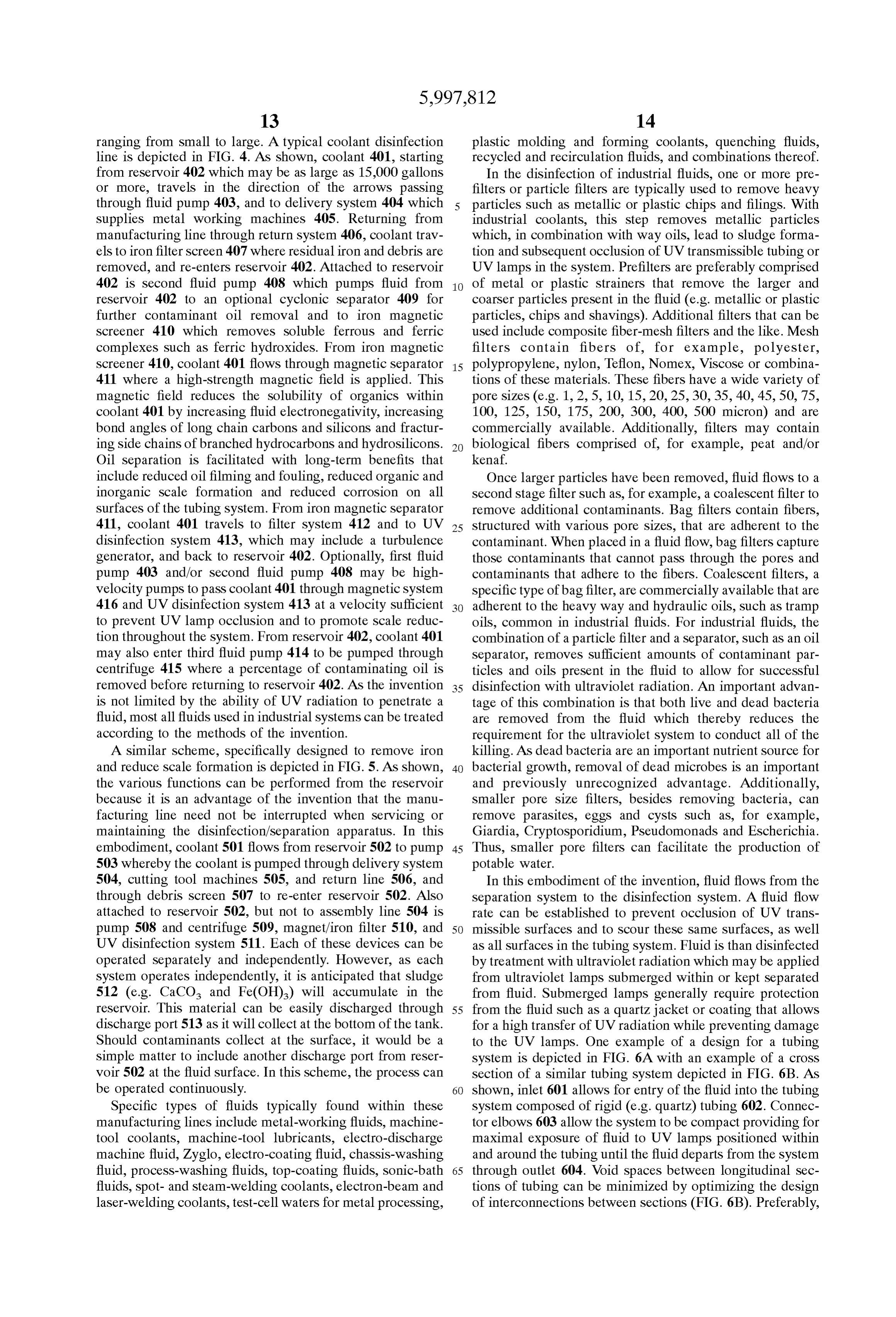
504, cutting tool machines 505, and return line 506, and In this embodiment of the invention, fluid flows from the through debris screen 507 to re-enter reservoir 502. Also Separation System to the disinfection System. A fluid flow attached to reservoir 502, but not to assembly line 504 is rate can be established to prevent occlusion of UV trans pump 508 and centrifuge 509, magnet/iron filter 510, and 50 missible Surfaces and to Scour these same Surfaces, as well UV disinfection system 511. Each of these devices can be as all Surfaces in the tubing System. Fluid is than disinfected operated Separately and independently. However, as each by treatment with ultraviolet radiation which may be applied System operates independently, it is anticipated that sludge from ultraViolet lamps Submerged within or kept Separated 512 (e.g. CaCO and Fe(OH)) will accumulate in the from fluid. Submerged lamps generally require protection reservoir. This material can be easily discharged through 55 from the fluid Such as a quartz jacket or coating that allows discharge port 513 as it will collect at the bottom of the tank. for a high transfer of UV radiation while preventing damage Should contaminants collect at the Surface, it would be a to the UV lamps. One example of a design for a tubing Simple matter to include another discharge port from reser System is depicted in FIG. 6A with an example of a croSS voir 502 at the fluid surface. In this scheme, the process can section of a similar tubing system depicted in FIG. 6B. As be operated continuously. 60 shown, inlet 601 allows for entry of the fluid into the tubing Specific types of fluids typically found within these System composed of rigid (e.g. quartz) tubing 602. Connec manufacturing lines include metal-working fluids, machine tor elbows 603 allow the system to be compact providing for tool coolants, machine-tool lubricants, electro-discharge maximal exposure of fluid to UV lamps positioned within machine fluid, Zyglo, electro-coating fluid, chassis-Washing and around the tubing until the fluid departs from the System fluid, process-washing fluids, top-coating fluids, Sonic-bath 65 through outlet 604. Void spaces between longitudinal sec fluids, Spot- and Steam-welding coolants, electron-beam and tions of tubing can be minimized by optimizing the design laser-welding coolants, test-cell waters for metal processing, of interconnections between sections (FIG. 6B). Preferably,
Page 21
the disinfection system is a dry system where the UV lamps ing oils, oil-Soluble cutting fluids, Semi-Synthetic fluids are placed in close proximity to, but not within the fluid. composed of a combination of Soluble oils and Synthetic This allows for easy UV lamp replacement and heat gener oils, Synthetic fluids for cutting and grinding both ferrous ated from the UV lamps can be disseminated without and non-ferrous alloys, propylene and ethylene glycol and damaging the fluid. A dry System requires infrequent Dowtherm. In addition, Some coolants are anti-freezes Such maintenance, a real advantage for this design. In one as, for example, propylene glycol. embodiment of the invention, ultraViolet treatment is applied In the assembly and manufacturing lines, coolants pick up at greater than about 12,000 microwatt seconds per cm of a Substantial amount of contaminants. Substantial means radiation, preferably greater than about 20,000 microwatt that the level of contaminants are increased So as to shorten seconds per cm, and more preferably greater than about the normal useful life of the fluid due to their concentration 40,000 microwatt seconds per cm. In the absence of a and interference with coolant function and to the presence of minimum amount of contaminants, as determined by flow an enhanced environment for microbial growth. Particles Speeds, fluid can be Successfully exposed to the killing Such as metallic or plastic filings or iron or Steel chips, effects of ultraviolet radiation. typically accumulate on and in the machines being cooled. The invention possesses many additional advantages. AS 15 other Particles Such as microorganisms, insects, insect parts and neither magnetic treatment nor ultraViolet radiation add These debris also collect in the reservoir and in the lines. particles are all swept-up in the fluid flow. Other chemicals to the fluid or modify fluid components, the contaminants include proceSS has no effect on the functionality of the fluid. A need hydraulic fluids and waylubricating oils, pretreating oils, oils. Lubricating oils have a low for chemicals Such as germicides and biocides, presently Viscosity, compared to way oils which are quite Viscous (i.e. used in the disinfectant of fluids, is greatly reduced or heavy oils and oils with long carbon chains). Tramp oils (i.e. completely eliminated. Examples include bromine, chlorine renegade contaminant oils that get into machine operations), and tricine. AS biocides are themselves expensive and pose which typically include way oils, also accumulate in the Serious health risks to workers, the Savings can be consid fluid. These contaminant Substances are Sticky, adhere to the erable. In addition, many chemicals are detrimental to the walls of pipes and the UV System components, and further efficiency and integrity of the fluid. Consequently, use of the 25 encourage microbial growth, especially bacterial growth in methods and apparatus of the invention greatly extends the the line and in the fluid reservoir. Such Substances also bind useful life and/or shelf-life of the fluid. In addition, odors bacteria to their molecular interface surfaces. Preferably, from contaminated fluid and Some biocides can be fairly these bacteria are removed during a physical Separation Step unpleasant. Use of the invention also reduces or eliminates thereby reducing the requirement of the ultraviolet to be the Such odors providing an improved air quality and working Sole bacterial control mechanism.
environment. In the disinfection process, coolant is Subjected to filtra Using the disinfection processes and apparatus of the tion by passing the coolant through a prefilter to remove invention, bacteria counts acceptable to federal (e.g. EPA or larger particles and debris. The prefiltered fluid is passed FDA), State or local regulations and various other health through a first Stage filter that removes finer particulate fields can be set for a particular fluid. The invention allows 35 matter. Such filters remove particles of greater than about for the possibility of multiple passes of the fluids to achieve 100 microns, preferably greater than about 50 microns, more such set microbial levels. Further, the invention provides a preferably greater than about 25 microns and Still more controllable resident time in the UV system of exposure to preferably greater than about 10 microns. Other UV radiation for Seconds or minutes. For example, in one contaminants, Such as way and other tramp oils are removed test using industrial fluid, a bacteria count before coolant 40 using one or more oil Separators which are, preferably, was processed through the oil Separator and UV system was dedicated to the removal of Such contaminants. In specific approximately 10 to 10 microorganism per ml. After a 24 instances it may be desirable to design the System to allow hour cycle, the microorganisms count was almost Zero. With Specific contaminants, Such as molecular iron and iron this process, costs for the disposal of contaminated coolants containing complexes, to remain. Such complexes can aid in and for coolant replacement are Substantially reduced. In 45 disinfection, for example, in the formation of ferrates. addition, chemical pollution to the environment is mini Liquid contaminants in a contaminated fluid vary greatly mized or can be avoided where processes are available for depending on the type of fluid and the use to which the fluid recycling used fluids. In addition, microbial counts follow is applied. For example, the principal liquid contaminants in ing UV treatment of Substantially opaque fluids can be an industrial fluid are heavy oils. Such as way oils and require further reduced by introducing turbulence to the fluid flow 50 an oil Separation System for removal to allow recycling of path thereby bringing bacteria to the fluid Surface for greater the fluid. Many techniques for the removal of oil from a killing exposure. continuous or running Stream of fluid are well-known to The methods and apparatus of the invention can be used those of ordinary skill in the art. For example, at least most in both closed and open Systems. In closed Systems, Such as of the oil can be removed from a fluid by passing the fluid both large and Small Scale assembly lines and other manu 55 through a plurality of oil Separators. Preferably, one of Such facturing lines, fluids Such as coolants flow down the line to oil Separators is a coalescent filter. Coalescent filters com cool and lubricate machine tools. Coolants are heat transfer prise fibers with predefined pore sizes wherein the fibers are mediums or thermofors and may be in liquid or a gaseous adherent to the contaminants. Such filters are commercially form having the property of absorbing heat from the envi available (U.F. Strainrite, Inc; Lewiston Me...). Other oil ronment and transferring that heat effectively away from the 60 Separators useful according to the methods of the invention Source. AS Such, coolants are used in the transportation include oil skimmerS and density centrifuges. Preferably, the industry, the tool manufacture industry and in most every pretreatment Steps include a Strainer Step to remove particles Small to large manufacturing plant. Coolants, as do most of greater than about 100 microns, a centrifugation Step to industrial fluids, come in a variety of colorS Such as gray, remove a large portion of the heavy oil contaminants, a red, yellow, white, green and blue, and may be fairly thick 65 prefilter Step to remove contaminants of greater than about in composition as compared to plain water. Types of cool 25 microns, and a coalescent filter for removal of oil and ants include petroleum-based, machine fluids and lubricat Small contaminants.
Page 22
An oil Separation Scheme that is useful for the methods of use of corrugated ultraViolet-transmissible tubing, U.S. Pat. the invention is depicted in FIG. 7. As shown, fluid flows Nos. 4,971,687 and 4,968,891, for use of thin films, U.S. Pat. through tubing system 701 in the directions indicated by the No. 5,494,585 for use of a cavitation process, and U.S. Pat. arrows. Fluid first passes through the magnetic field at Nos. 3,527,940 and 4,766,312, for maximizing radiation magnet unit 702 (for oil separation and Scale control), treatment by passing fluids through a helical path. In downstream to oil separation unit 703, and continues to UV addition, Such radiation can include ionizing radiation, Such disinfection unit 704. Oil separation unit 703 may contain an as gamma radiation or X-rays in place of ultraViolet. Thin oil adsorption material Such as, for example, particulate films may be shaped by the structure of a portion of the copolymers, polypropylene, polyester, peat, kenaf, cellulose ultraviolet transmissible tube. The fluid may be guided into fibers or combinations of these materials, or one or more a thin film with a thickness of less than about 5 mm, conventional oil separation devices Such as, for example, a preferably less than about 4 mm, and more preferably leSS cyclonic Separator, a filter bag, a coalescent filter, a skimmer than about 2 mm. AS radiation of Substantially opaque fluids or a centrifuge. Each of the devices can be used to remove can disinfect about 1 mm to about 1.5 mm of fluid, radiation contaminating oil from the fluid and the oil will be more transmitted from all sides of a 2 mm to 3 mm fluid flow can effectively removed due to the immediately prior magnetic 15 be disinfected. Where complete sterilization of the fluid is treatment. desired, thin film technology may be useful. A wide variety Oil adsorbents are highly useful materials and can collect of ultraViolet Sterilization devices or Self-contained units can many times their weight in oil and other liquids. Biomass be used with one or a plurality of ultraviolet lamps both materials. Such as, for example, peat and kenaf are non within, between and Surrounding the tubing. abrasive adsorbents, and are preferred adsorbents for the Tubing and thus fluid exposure to the radiation can be Separation of contaminants. Peat adsorbS polar organic Sub optimized by creating an orientation pattern of UV lamps stances and can be used raw, aged or Semi-aged with or around the tubing with ultraviolet reflective surfaces direct without mechanical drying. Aged peat is more useful for ing the radiation toward the fluid. Radiation exposure is adsorbing compounds containing carboxyl groupS. Semi highest at the fluid-Surface interface. A croSS-Section of a aged peat is more useful for adsorbing amine group 25 fluid pipe 802 with a surrounding UV system is shown in containing compounds. Peat and kenaf, another plant FIG. 8. As depicted, ultraviolet lamps 801 radiate energy material, are also useful for adsorbing heavy metals and into a fluid contained within UV-transmissible tube 802. most all hydrocarbons. In fact, kenaf adsorbs ten times its With opaque fluids, this tube may contain a tube within a ashed weight of oil. Synthetic materials can also be used as tube configuration. A hollow tube or solid center 803 is adsorbents including polyethylene and polyester. One of the surrounded by wall 804 the surface of which is coated with advantages for these materials is that as an adsorbent in a UV reflective material 805. With opaque fluids, tube 802 fluid flow, they do not contribute to the carbon loading of the may contain inner tube 803 which may be hollow and fluid. Further, these materials are extremely user friendly transmit air under pressure discharged through walls 804 or and can be molded into a shape Suitable for most any through pores in walls 804 to create turbulence. UV reflec operational condition. Adsorbent can be packaged as sheets 35 tive material is also present on UV reflectors 806 positioned or blocks, particularized, powdered or in a mesh, and around tube 802 so as to maximize energy input to fluid flow packaged into bags or retaining vessels. Further, these 810. Additionally, reflectors 809 may be placed in close materials are fairly inexpensive and Straightforward to main proximity to UV lamps 801 to optimize reflection of UV tain or replace. radiation to UV transmissible tube 802. Alternatively, 803 Once leSS than a specified level of contaminants has been 40 may be a bead, cone or other mechanism linked by filament reached, the contaminant-reduced fluid can be Successfully as in a chain to create turbulence within passing fluid. Ribs irradiated with a disinfecting amount of ultraViolet radiation 808 are present on inner surface of wall 804 to generate Such that any contaminants that remain do not interfere with turbulence within fluid flow 810. Alternatively, fluid flow disinfection of the fluid. The disinfecting amount of radia 807 through tube 802 may be in the form of a thin film to tion depends on the flow rate and volume of the fluid being 45 allow for complete penetration of UV radiation. Thin film treated at any one moment. For most applications, radiation depth will depend on the opacity or translucency of the fluid is administered at from at least about 15,000 microwatt and, in general, opaque thin films will have a depth of leSS seconds/cm or more, depending also on the type of ultra than about 3 mm and transparent thin films will have a depth Violet lamps, the ultraViolet transmissibility of the tubing, of greater than about 3 mm.
the orientation of lamps around the fluid-filled tubes and the 50 UltraViolet reflective material includes, for example, an structure of the tubing (e.g. flat verses rounded). As the UV aluminum, a titanium or titanium nitrate based material, or lamps can be separated from the fluid, the method is a combination thereof. Preferably, the reflector is coated by preferably a dry disinfecting System. Although generally not a Sputtering process whereby the coating material is depos required or necessary, it is also possible to Sterilize a fluid by ited in a vacuum onto a Solid Support Such as an aluminum increasing the amount of ultraViolet radiation administered. 55 or teflon surface. In addition, UV lamps may be partially Ordinarily, though, Sterilization is not required to maintain a coated with UV reflector substances or UV blocking Sub Safe and workable cooling System. stances to reflect and to direct energy output and/or prevent The oil Separator and the ultraViolet radiation generating exposure of other surfaces to UV radiation. System can be designed as modular units to further increase Many types of reflectors are known to those of ordinary convenience and to reduce overall costs. AS Such, the System 60 skill including polished aluminum reflectors, described in can be operated continuously, Subject to periodic mainte U.S. Pat. No. 4,534,282, reflectors mounted to the frame, nance for UV lamp changes or removal of accumulated described in U.S. Pat. No. 3,634,025, elongated curved contaminants, for a period of greater than one week, greater reflectors, described in U.S. Pat. No. 4,766,321 and outward that one month, greater than one year or even longer. reflecting reflectors.
All types of conventional radiation treatment can be 65 As known to those of ordinary skill in the art, ultraviolet administered to the contaminant-reduced fluid including radiation can be directed to kill eukaryotic cells, bacterial treatment methods described in U.S. Pat. No. 4,798,702, for cells, fungi and Spores, Virus particles and almost any living
Page 23
microorganism. Based on the intensity of the radiation Turbulence-generating Systems that encourage transverse treatment, one of ordinary skill can choose to disinfect or motion include aeration Systems that create gaseous bubbles completely Sterilize the fluid. Sterilization is usually unnec within the tube. Preferably, the gas does not interact with the essary for industrial fluids, but is often required to meet EPA fluid components. Typical gasses that can be used for most or FDA guidelines for products regulated by government fluids include, for example, air, carbon dioxide, Oxygen, guidelines Such as pharmaceuticals and animal products. hydrogen, helium, nitrogen, argon and combinations of Industrial fluids, for example, typically contain between gasses, any of which may be pressurized. In addition, this about 10 to about 10” bacteria per ml. Reduction of technique is not limited to gas. Liquids may be forced into bacterial levels to at or less than about 10 is generally the inner tube as well creating turbulence in the fluid as the required to provide a Safe and risk-free working environ liquid exits holes within the inner tubing walls. Liquids ment as well as to extend coolant life. Treatment of con which can be used include the liquid itself, which may be the taminated fluid, according to the methods of the invention, contaminated liquid or liquid that has been treated according kills greater than 90% of the microorganisms in the con to the invention, an inert liquid or another liquid that does taminated fluid, preferably greater than 95%, and more not negatively interact with the fluid being treated. The tube preferably greater than 99%. This reduces the bacterial load 15 within a tube configuration preferably has a controllable of the fluid by at least about one log, preferably at least about pressure differential within the tubing. 2 logs, more preferably at least about 3 logs. Increased Turbulence can also be generated by Suspending articles disinfection is possible by incorporating multiple exposure within passes to decrease the bacterial load of the fluid at least Vanes, the fluid Stream Such as, for example, ridges, helical impellers, baffles, projections, Vanes, paddles, about 4 logs, preferably at least about 5 logs, and more preferably at least about 6 logs or more when necessary. wheels, beads, cones or Slotted cones, or almost any geo Alternatively, it may only be necessary to remove or kill leSS metric structure. Such structures or turbulators or agitators than 10% of the microbial contaminants provided the system may be on a String, free in the fluid or free, but confined in is operated continuously with the fluid repeatedly passed a Section of the tubing. Such structures may be constructed through the disinfection System. In this manner, a continual of a metal Such as Steel or a composite polymer. The beaded reduction of 10% per pass or per total turnover of the fluid 25 String is placed into the lumen of a tube along the direction Volume will reduce microbial contamination to near Zero in of fluid flow. As fluid impacts the bead, fluid is directed a Set time frame. Treatment times and rates vary depending transversely or turbulently to the sides of the tube where on the volume of fluid being treated and the amount of ultraViolet radiation exposure is maximized. Preferably, the contamination, the rate of fluid flow and the rate of Surviving bead is slightly smaller than the lumen of the tube. However, microorganism growth that would depend on the level of a variety of sizes may be utilized the only requirement being biocide in the System and the nature of the other components that they fit within the lumen and not cause an impractical within the fluid. Therefore, treatment may be performed, for or high head preSSure in the System. Such devices have the example, in a continuous System operated for months, further advantage that they can be easily replaced without weeks, days or hours to reduce the bacterial load to desired requiring replacement of the entire tubing System. Combi levels and to maintain Such levels.
nations of these techniques may also be utilized.
Disinfection methods may be further enhanced by estab 35 Another embodiment of the invention is directed to com lishing turbulence generating Systems in the fluid Stream binations of fluid disinfection treatments Such as those during irradiation. AS ultraViolet radiation cannot pass more described above. Fluids may be treated with a combination than about 1 mm to about 2 mm into most fluids, and leSS than 1 mm in opaque fluids, it is important to maximize of contaminant removal and turbulence generation followed exposure of the microorganisms in the fluid to ultraViolet 40 by radiation treatments. Such treatments may be further radiation. AS fluid travels transversely as in a turbulent or Supplemented with conventional treatments Such as, for non-laminar manner to fluid flow in the tubing, there is a example, filtration, centrifugation and the addition of bio greater likelihood that the microorganisms in the fluid will cides including anti-bacterial and anti-fungal agents. be subjected to ultraviolet treatment. Turbulence should be However, as the combination is highly effective, the amount Sufficient to provide a Reynolds number greater than that 45 of biocidal agents that are added can be greatly reduced as defining a laminar flow or greater than about 4,000 and compared to conventional methods. The working environ preferably greater than about 10,000. By encouraging micro ment would be improved due, in part, to the lack of noxious organisms to move transversely, microbes are brought to the fumes caused by microbe-induced decaying fluid, and the Surface of the fluid at the inner surface of the lack of biocides and/or microorganisms, greatly improving UV-transmissible tubing and not hidden within mid-sections 50 air quality. Health risks to workers are also greatly reduced. of the tube. Passage of fluid and microorganisms within the Another embodiment of the invention is directed to an fluid are moved from Zones of no or low UV radiation to apparatus for disinfecting a fluid. The apparatus comprises a Surface Zones of high UV radiation. In this manner not only tubing System, a magnet, which may be a permanent magnet is killing effect magnified, but the turbulence creates a or electromagnet, an ultraViolet radiation-treatment System, Scouring effect within the tubing. Radiation can also induce 55 a turbulence-generating System and/or a contaminant oxidation of certain chemicals that may be present in the Separation System which, for example, may be specific for fluid which may add to both the Scouring and killing effects. particles, microbes, oil or a combination of these contami Tube sizes that guide the flow of turbulent fluid are not nantS.
limited by the ability of UV radiation to penetrate the fluid. In a dry modular apparatus, the tubing System guides the Tube diameters which can be utilized for this method may 60 passage of the fluid at a determinable flow rate through the have a diameter of greater than about 4 mm, preferably apparatus with the UV lamps separated from the fluid. greater than about 6 mm, and more preferably greater than Tubing of the System is composed of ultraViolet about 10 mm or more. Tube sizes of greater than two inches, transmissible material Such as, for example, a greater than three inches and even greater than four inches, fluoropolymer, as described in U.S. Pat. No. 4,798,702. typical in most industrial Settings where the fluid is more 65 Tubing which is useful for the tubing system should pref translucent and leSS opaque, are also applicable to this erably be capable of withstanding pressures of greater than method. about 70 psi, and preferably greater than 150 psi, have a
Page 24
thickness of between about 20 to about 80, and more both the inside and outside, and even between, the coils. AS preferably 60, thousandths of an inch, and be transmissible the energy imparted to the target fluid is proportional to the to greater than 40% of the ultraviolet radiation being square of the distance of the UV lamps to the fluid, that applied, preferably greater than 50% and more preferably distance should be minimized to maximize the amount of greater than 60%. A preferred type of tubing has been energy transmitted to the fluid. The unit can be ventilated or identified and is composed of monofluoroalkyOXy polymer, air conditioned to prevent heat build-up as necessary to perfluoroalkoxy polymer (Zeus Industrial Products, Inc.; prolong the life of the UV lamps and So as not to damage the Orangeburg, S.C.), Hy flon MFA which is a fluid.
co-polymerization of tetrafluoroethylene and perfluorom The apparatus may also comprise tanks or other fluid ethylvinyl ether, or fluorinated ethylene propylene (FEP) retention vessels that are temperature regulated. Cooling or (Product No. 3E 750 SW 0; Zeus Industrial Products, Inc.; heating of the fluid is Sometimes necessary for transportation Orangeburg, S.C.). These types of tubing are resistant to Such as, for example, in the transportation of beverages (e.g. fouling, have a high corrosion resistance, are both Strong and Soft drinks, beer, wine). Further, the apparatus may also light weight, and are highly UV transmissible with trans comprise a microorganism detection System. This System mission factors of greater than about 55%. Preferably, the 15 would Screen for harmful microorganisms in the fluid Such as infectious bacteria (e.g. Salmonella, E. Coli, V. cholerae, tubing is flattened or oval shaped with a cross-sectional Shigella), diameter ratio of about 1 to about 0.35. Surface area exposed Cryptococcus, virus (e.g. Hepatitis, poliovirus) or fungi (e.g. to UV radiation is increased and the Surface area of tubing to be made potable. Candida, Paracoccidioides) in a water Supply Shadowed by adjacent coils of the same spiral or by the are known to those Multiple of detection devices and methods ordinary skill in the art and can be coiled lengths of tubing are minimized. The flatted Surface coupled electronically for the automatic addition of biocides may be modified to increase the wetted Surface area by or the control of UV radiation treatment times or intensities. incorporation of longitudinal Serrations, coarse Serrations or Such devices may be immunologically-based methods of waves. These modifications increase UV effectiveness by detection with results measured by optical (e.g. increasing the area of the fluid exposed to the UV radiation. colorimetric), luminescent (e.g. luciferin) or enzymatic (e.g. The tubing System may also comprise one or more inlet 25 alkaline phosphatase) means.
and outlet ports attached to opposite ends of a coiled tube. The apparatus may also contain a turbulence-generating The inlet ports allow for the flow of fluid from the line or the System to maximize exposure of the fluid to the radiation. reservoir into the disinfection unit. The outlet port allows for The turbulence-generating System should preferably be the flow of disinfected fluid back to the line Such as a placed into the tubing wherein the fluid is exposed to the manufacturing or assembly line. Tube Surfaces may be radiation. Examples of turbulence-generating Systems Smooth, furrowed, wrinkled, indented, transverse ridged or include structures attached to the walls of the tube or corrugated, and the tubing may be coiled, parallel, twisted, otherwise free-floating in Specified areas of the lumen of the conical, Serpentine or in a helix at the point of radiation tube. Such structures include nearly any shaped article Such treatment. UltraViolet lamps can be positioned outside and as paddles, beads, cones, Vanes, ribbons and the like, any of inside the tubing configuration as well as between the tubes. 35 which may be slotted, and which may be fixed to tubing Tubing has a flattened to rounded cross Section (e.g. oval). walls, attached to each other or attached to a String and However, the System may be configured to create a thin film Suspended in the fluid. Fixed Structures may be placed at Set of fluid (flattened) at the point of radiation treatment to angles to the laminar flow of the fluid, preferably up to about maximize radiation exposure. 90, such as, for example, about 20, about 30, about 45, The contaminant Separation System can be designed to 40 about 60 or about 75. Other turbulence-generating systems remove particulate and other contaminants from the fluid. include tube within a tube configurations that allow for a Particulate matter can be removed with filters having pore preSSure differential, ultrasonic vibrations, Split-flow SyS sizes designed to remove particles of greater than 100 tems or aeration within the fluid. Another turbulence gen micron, preferably greater than 50 micron, and more pref erating mechanism, which does not require intrusion into the erably greater than about 10 micron. The contaminant Sepa 45 lumen of the tube, comprises a periodic modification of ration System may contain an oil Separator designed to tubing croSS Sectional shape. For example, rounded tubing remove at least most of the oil from the fluid. Examples of may be flattened at regularly or irregularly Spaced intervals. Suitable types of oil Separators include Skimmers, centri As shown in FIG. 10, fluid enters the tubing system through fuges and coalescent Separators. Other unwanted liquids can fluid entry port 1001 of flattened tubing 1002 traveling be removed by a separation means particular to the type of 50 through transition Zone 1003 to circular Zone 1004 and to liquid. Such Separation means are known to those of ordi another transition Zone 1005 and returning to flattened nary skill in the art. tubing 1006. In cross section, flattened tubing 1007 extends In addition to a contaminant Separation System, the appa longitudinally from circular Zone 1008 containing lumen ratus may also includes an ultraViolet radiation System. The 1009. Alternatively, flattened tubing may be rounded at radiation System is comprised of one or more ultraViolet 55 spaced intervals. As also shown in FIG. 10, fluid enters the lamps in close proximity to the tubing System. AS the lamps tubing system through fluid entry port 1010 of rounded do not come into direct contact with the fluid, the apparatus tubing 1011 traveling through transition Zone 1012 to flat may be described as a dry system (i.e. the lamp does not tened Zone 1013 and to another transition Zone 1014 and come into direct contact with the fluid contained within the returning to rounded tubing 1015. In cross section, rounded UV-transmissible tube). In a dry system, fluid components 60 tubing 1017 extends circularly from flattened Zone 1016 are not Subjected to unwanted heating from the UV lamps. containing lumen 1018. The apparatus may also contain Further, the UV lamps are not cooled by circulating fluid circuitry appropriate for proper monitoring and control of all and, therefore, maintain a temperature high enough for aspects of the apparatus. The additional of computer control optimum generation of UV radiation. Also, maintenance of can also be utilized to create units that are completely or lamps is minimized due to the Separation of dirty or con 65 partially automated.
taminated fluid from the lamp surfaces. Preferably, there are Another feature of the invention is that disinfection units, a plurality of ultraViolet lamps Surrounding a coiled tube on comprising an apparatus for performing a method of the
Page 25
invention, can be completely portable. Units do not require Filtered fluid is passed to UV unit 911 where the fluid is bulky machinery, or attachment to fixed structures. Portable disinfected and the disinfected fluid is expelled through apparatus can be transported by land, Sea or air, and Set up outlet port 912. AS the unit is dry modular in design, it can in most any location. Power Supplies required to operate the be used to disinfect many different types of fluids. unit are not onerous and can also be provided from portable According to an embodiment of the general process of the Sources including Solar or wind power. AS Such, apparatus of invention, coolant to be disinfected is first treated by passing the invention can be used in remote locations for temporary through a Screen to remove metallic particles and other or permanent water purification by civilians or military debris. Coolant is next run through an on Site commercial perSonnel. No specialized training is required to operate a centrifuge to reduce contaminant concentrations to approxi unit other than basic information. Further, as the apparatus mately two percent. Coolant to be treated is drawn into the can be Self-contained, no on-site construction is required. System by a pump mechanism. The pump forces coolant into The unit can be transported intact to the desired location. a first magnet to remove ferrous and ferric complexes. The Another embodiment of the invention is directed to fluids fluid than passes to a Second magnet that modifies contami treated according to the methods of the invention. Such nants So as to increase hydrophobicity and molecular shape. fluids include liquid which, after treatment, are Substantially 15 The fluid is then forced into an oil Separator device con free of microbial contamination and, optionally, other con taining a filter vessel under pressure which contains a filter taminants as well as way and tramp oils, microbial particles cartridge. The cartridge will normally contain a 10 to 20 and other particulate materials. Substantially free means that micrometer pore size which facilitates Separation of the oil the population level of microbes has been reduced to a level and binding of the oil to the fiber structure of the cartridge. that does not pose a risk to workers, resulting in an improved Such filtration performs the important role of removing large quality to the working environment. Such fluids include amounts of both living and dead bacteria. Removal of the machine tool coolants, machine tool lubricants, electrodis dead bacteria reduces nutrient loading in the fluid. The charge machine fluid, Zyglo, electro-coating fluid, chassis differential pressure between the input and the output of the Washing fluid, top-coating fluids, Sonic-bath fluids, Spot- and filter vessel is used to monitor the condition of the filter Steam-welding coolants, electron-beam and laser-welding 25 cartridge and can be read at the electronic module. When the coolants, test-cell waters for metal processing, plastic mold preSSure reaches the Specified differential, in most cases the ing and forming coolants, quenching fluids, recycled and greatest differential, the filter cartridge has filled with con recirculation fluids and combinations thereof. taminant oil and must be replaced. Rate of oil accumulation Additional fluids include petroleum products and petro will vary depending upon the amount of oil in the coolant chemicals. Such as, for example, petrolatum, natural gas, and the viscosity of the oil as well as the type of coolant. The gasoline including diesel fuel, kerosene and all forms of fuel fluid is forced under pressure into the germicidal module and for internal combustion engines, ethylene, ammonia, Syn disinfected before being discharged from the outlet. thetic petrochemicals, fertilizers, paraffin, naphthene, alco hols Such as methanol ethanol and butanol, paints, Solvents 35 Example 2 and other like chemical compounds. Yet other fluids includ System Designs for Selected Fluids.
ing water Such as potable water, water to be consumed in System designs for Selected fluids, shown in Table 1, are areas of Suspected contamination, water Supplies from natu designed to provide a useful combination of treatments and ral or man-made emergencies, water used during military exposures for individual types of fluids.
operations, third-world water Supplies, livestock water and beverages Such as, for example, flavored and plain water, 40 TABLE 1.
flavored drinks and drink blends, vegetable, fruit and other juices, Soft drinks, beer, wine and other liquors, may also be Selected System Designs treated according to the method of the invention. SYSTEM SEOUENCE FLUIDS The following examples illustrate embodiments of the 45 No. 1 UV Water, clean fluids; clear or invention, but should not be viewed as limiting the Scope of opaque fluids the invention. No. 2 Screen-Oil Separator Filter Industrial fluids such as chassis wash fluids,
EXAMPLES electrocoat fluids and topcoating
Example 1 50 No. 3 Screen-Oil Separator Filter- As in No. 2 adding A Magnetic/UV Disinfection Apparatus. UV contaminated fluids such as An example of one embodiment of the invention, an metal working fluids and latex solutions apparatus, is shown in FIG. 9. AS shown, the apparatus is No. 4 Screen-Pre-filter-Filter Metal cutting fluids, industrial entirely contained on mobile cart 901 which is on casters separator-UV fluids and, consequently, quite mobile. The basic unit comprises 55 No. 5 Screen-High gauss magnet-
Metal cutting fluids, industrial fluids preparation 902, ultraviolet module 903 and electronics No. 6 Screen-High gauss magnet- Fuels, e.g. diesel, kerosene module 904, which may contain a fan for internal tempera UV ture regulation, gauges reporting on the condition of the unit No. 7 Screen-Low velocity First Metal cutting fluids, industrial and/or the Status of the fluid flow, indicator lamps and stage magnet-High gauss fluids
control switches. Fluid enters through inlet port 905, is 60 Separator-UV forced by pump 906 thorough the apparatus to first magnet No. 8 Screen-Fe(OH)3 -High gauss Swimming pool and spa 907 for enhanced oil removal, to second magnet 908 for magnet-UV water; industrial fluids not removal of ferrous and ferric complexes that could foul the No. 9 subject to oxidation damage. UV transmissible tubing, block UV radiation and corroding Screen-Fe(OH) Air-UV- Potable water; water to be High gauss magnet-UV disinfected for consumption;
metallic materials in the system, and to prefilter 909. From 65 High potential to kill spores, prefilter 909 fluid travels through main filter 910 where the cysts and parasitic eggs largest portion of contaminating materials are removed.
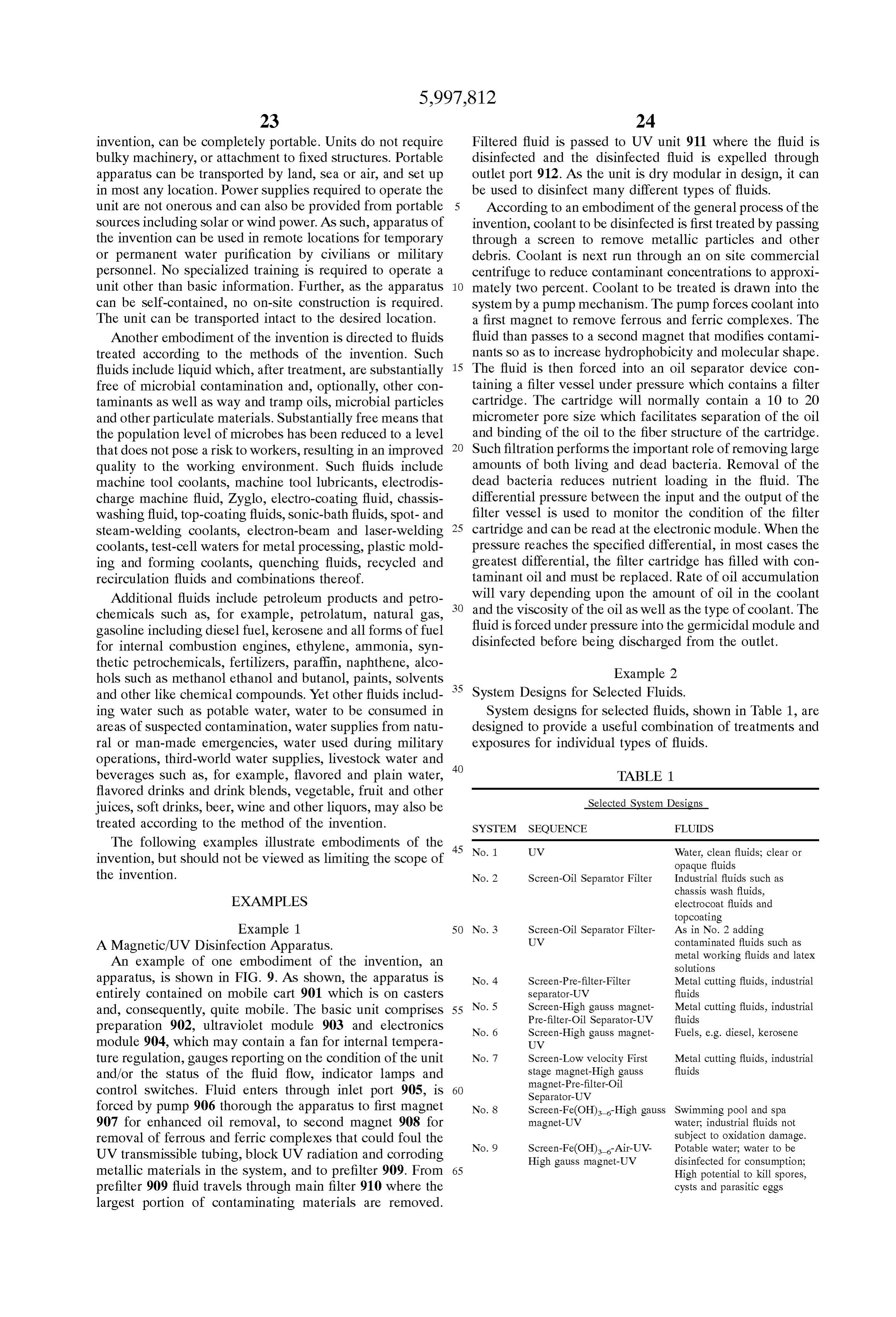
Page 26
effects as in No. 5. Filter system to remove contaminants
TABLE 1-continued to prevent occlusion of UV system.
System 11: Magnet Serves to enhance dispersion of the
Selected System Designs biocide within the fluid increasing its effectiveness, Mag
net causes activation of Spores thereby increasing their susceptibility to biocide.
No. 10 Screen-Low velocity First Swimming pool and spa System 12: Ferrates created to enhance disinfection of stage magnet-High gauss water; industrial fluids not biocides, Magnet Serves to enhance dispersion of the magnet-Pre-filter-Filter subject to oxidation damage separator-Air-UV biocide within the fluid increasing its effectiveness, Mag No. 11 Screen-High gauss magnet Biocide treated industrial 1O net causes activation of Spores thereby increasing their fluids such as metal cutting susceptibility to biocide.
fluids Other embodiments and uses of the invention will be
No. 12 Fe(OH) -UV-High gauss Biocide treated industrial magnet fluids such as metal cutting apparent to those skilled in the art from consideration of the fluids Specification and practice of the invention disclosed herein.
15 All U.S. patents and other documents referenced herein, for
System 1: Occlusion dependent upon velocity of fluid being whatever It is reason, are specifically incorporated by reference.
intended that the Specification and examples be con treated sidered exemplary
System 2: Screen to remove debris in fluid; Hydrocarbon invention being indicated only, with the true Scope and Spirit of the contaminant Separation dependent upon pore size and by the following claims. composition of the filter, e.g., coalescer; Fluid velocity of We claim:
1. A method for disinfecting a contaminated fluid that is factor. Filter can be composed of Standard materials. Such Substantially as polypropylene or nylon or can be composed of peat or opaque comprising kenaf, a Southern plant providing increased adsorption passing the fluid through a magnetic field at a Velocity of capacity and affinity. greater than about 1 meter per Second and System 3: Screen to remove debris in fluid; Hydrocarbon 25 irradiating the fluid with a disinfecting amount of ultra contaminant Separation dependent upon pore size and Violet radiation without shaping Said fluid into a thin composition of the filter, e.g., coalescer; Fluid velocity of film of less than 5 mm.
factor. Filter can be composed of Standard materials. Such 2. The method of claim 1 wherein the contaminated fluid as polypropylene or nylon or can be composed of peat or kenaf, a Southern plant providing increased adsorption isa liquid an aqueous fluid, an industrial fluid, a combustible fuel or beverage.
capacity and affinity. 3. The method of claim 1 wherein the contaminated fluid System 4: Pre-filter bag removes iron-sludge and particles is Selected from the group consisting of water to be made that would occlude separator filter. Fluid velocity a factor. potable, beverages, industrial Water, coolant, lubricating oil, Other effects as in No. 3.
System 5: Molecule alteration resulting in increased trap 35 thereof.fuel, petrochemicals, alcohols, acids and combinations ping of contaminants given equal Size pores as without 4. The method of claim 1 wherein the contaminated fluid magnet, Increased filter effect due in part to enhanced polarity of H2O caused by the magnet. Decreased adher is an aqueous fluid and Said aqueous fluid is passed through ence to fluoropolymer UV tube due to alteration of the magnetic field at a velocity of from about 2 to about 5 hydrocarbon Side chains. High gauSS permanent or elec feet per Second.
trostatic magnet is one of few forces that can pass directly 40 5. The method of claim 1 wherein the contaminated fluid through solids. This enables creation of flux density that is an organic fluid and Said organic fluid is passed through can cause activation of Spores, Ova, cysts and eggs thereby the magnetic field at a velocity of from about 10 to about 50 increasing their Susceptibility to other Stresses Such as, for feet per Second.
example, UV or biocides. Magnet also activates metabo 6. The method of claim 1 wherein the magnetic field is lism of vegetative cells increasing their Susceptibility to 45 generated by an electromagnet or a permanent magnet. other StreSSes as well. Potential Synergism between mag 7. The method of claim 1 wherein the magnetic field net and UV in affecting target DNA and RNA molecules. strength is between about 600 to about 9,000 gauss. Magnetic activation of calcium carbonate, Fe(OH), 8. The method of claim 1 further comprising the step of BaSO, BaCO, CaSO to prevent scaling. Aids flow as passing Said fluid through a contaminant Separation System. well as preventing microbial growth habitat. Other effects 50 9. The method of claim 8 wherein the contaminant as in No. 4. Separation System comprises one or more filters or oil System 6: Effects as above in No. 4 without filters for fluids Separators.
that do not contain contaminant hydrocarbon oils. 10. The method of claim 9 wherein the one or more filters System 7: Trapping of ferric complexes to reduce fouling of comprises a magnetic filter that removes ferrous and ferric fluoropolymer tubing, reduction of iron-related corrosion. 55 complexes.
Others effects as in No. 5. 11. The method of claim 9 wherein the one or more oil System 8: Fe(OH) introduced to provide disinfecting Separators contains an oil adsorption material Selected from ferrates which will augment the UV and increased killing the group consisting of a particulate copolymer, potential. polypropylene, polyester, peat, kenaf, cellulose fibers and System 9: Introduction of ferrates followed by air and UV 60 combinations thereof.
will create additional oxidation power of OZone and 12. The method of claim 9 wherein the one or more oil hydrogen peroxide, especially at low wavelength UV Separators comprises a cyclonic Separator, a filter bag, a Such as 181 nm. Iron catalyzed oxidation of organics. coalescent filter, a skimmer, a centrifuge or a combination Magnet and final standard UV (253.7 nm) provide syn thereof.
ergistic killing power. Others effects as in No. 5. 65 13. The method of claim 1 wherein the contaminated fluid System 10: OZone and hydrogen peroxide created-ferric has a bacterial load that is reduced at least 1 log after complexes removed; Synergistic killing activity, Magnet irradiation.
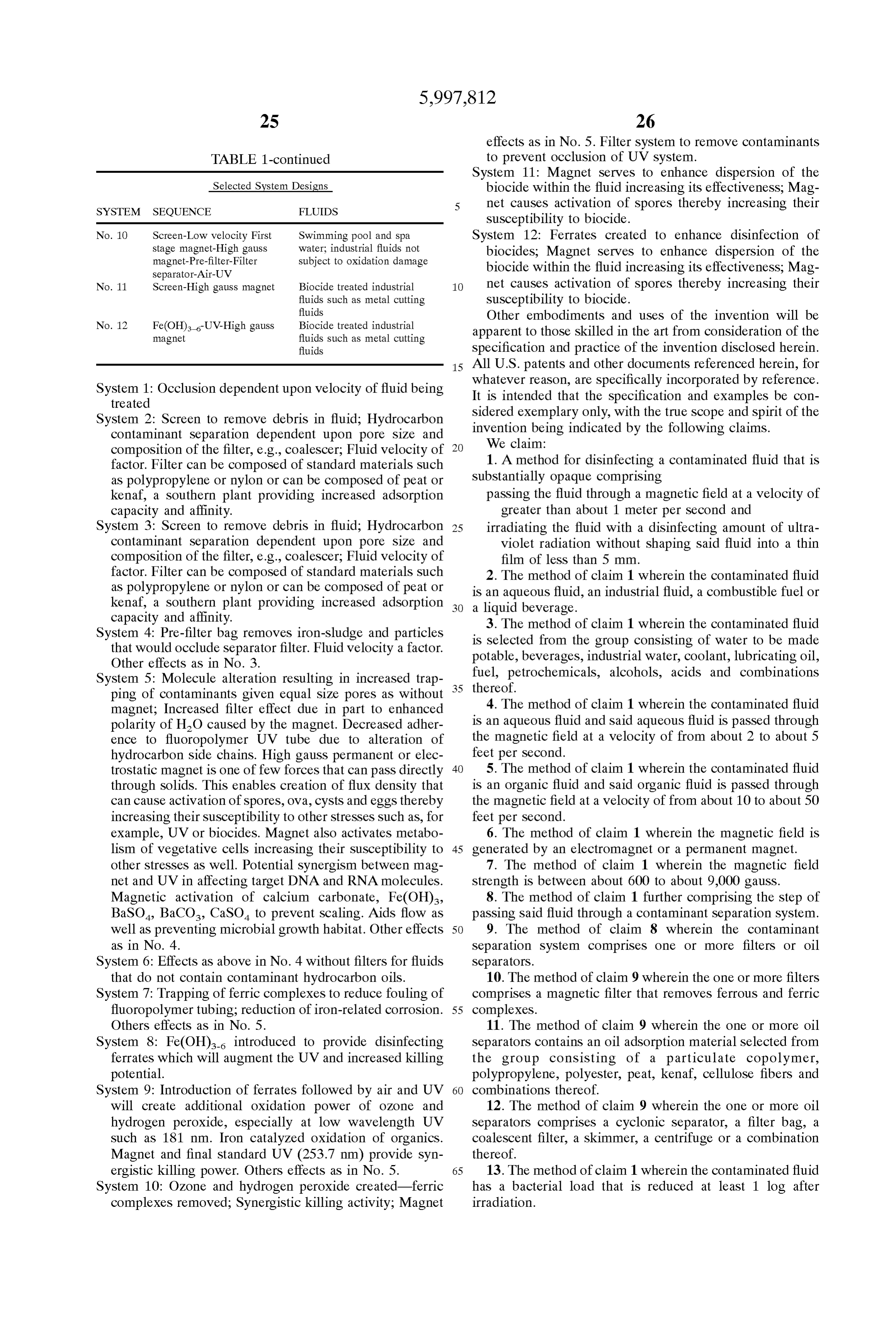
Page 27
14. The method of claim 1 wherein the contaminated fluid into a thin film of less than 5 mm, at a velocity of has a bacterial load that is reduced at least 2 logs after greater than about 1 meter per Second. irradiation. 27. The method of claim 26 wherein the fluid is an 15. The method of claim 1 wherein the contaminated fluid aqueous fluid, an organic fluid, an industrial fluid or a is contained within a closed System and the bacterial load combustible fluid.
within said system remains below about 10 microorganisms 28. The method of claim 27 wherein the combustible fluid per ml. is Selected from the group consisting of diesel fuel, gasoline, 16. The method of claim 1 wherein the step of passing
Said fluid through the electric field reduces Scale adherence. hydraulic fluid, machine oil, natural gas, petrochemicals, 17. The method of claim 1 further comprising the step of alcohols, acids and combinations thereof. creating turbulence in the contaminated fluid during irradia 29. The method of claim 26 wherein the magnetic field is tion. generated by an electromagnet or a permanent magnet. 18. The method of claim 17 wherein turbulence is created 30. The method of claim 26 wherein the magnetic field by Shape modification of a tubing System that contains and strength is between about 600 to about 9,000 gauss. guides passage of Said fluid. 15 31. The method of claim 26 wherein the fluid disinfection 19. A fluid disinfected by the method of claim 1.
20. A method for disinfecting a fluid that is substantially radiationcomprises
System treatment, a microbe filter, ultraViolet or ionizing ultrasound treatment, heat treatment, the opaque comprising addition of a biocide or pasteurization of Said fluid. passing oxygenated fluid containing molecular iron 32. The method of claim 26 further comprising the step of through a magnetic field at a Velocity of greater than passing Said fluid through one or more filters. about 1 meter per Second wherein Said magnetic field is 33. The method of claim 32 wherein the one or more Sufficient to form a disinfecting amount of ferrates.
21. The method of claim 20 wherein the fluid is supple filters comprise oil separators, particle filters, or filters mented with an oxidizing agent to form Said oxygenated containing magnets.
fluid. 25 34. A fluid treated by the method of claim 26. 22. The method of claim 21 wherein the oxidizing agent 35. A method for disinfecting a contaminated ultraviolet is hydrogen peroxide, OZone or a combination thereof. opaque fluid comprising passing the contaminated fluid 23. The method of claim 21 wherein the fluid is supple through a magnetic field and heating the contaminated fluid mented with air or oxygen and Subsequently treated with to a pasteurizing or Sterilizing temperature for a period of Sufficient ultraViolet radiation to form Said oxidizing agent. time.
24. The method of claim 20 wherein the disinfecting 36. The method of claim 35 wherein the contaminated amount of ferrates is greater than about 10 mM. fluid is an aqueous fluid, an organic fluid, an industrial fluid 25. A fluid disinfected according to the method of claim or a combustible fluid.
2O. 37. The method of claim 35 further comprising the step of 26. A method for treating a fluid that is substantially 35 passing Said fluid through one or more filters. opaque comprised of 38. A fluid disinfected by the method of claim 35. passing the fluid through a magnetic field and an ultra
Violet disinfection System, without Shaping Said fluid k k k k k
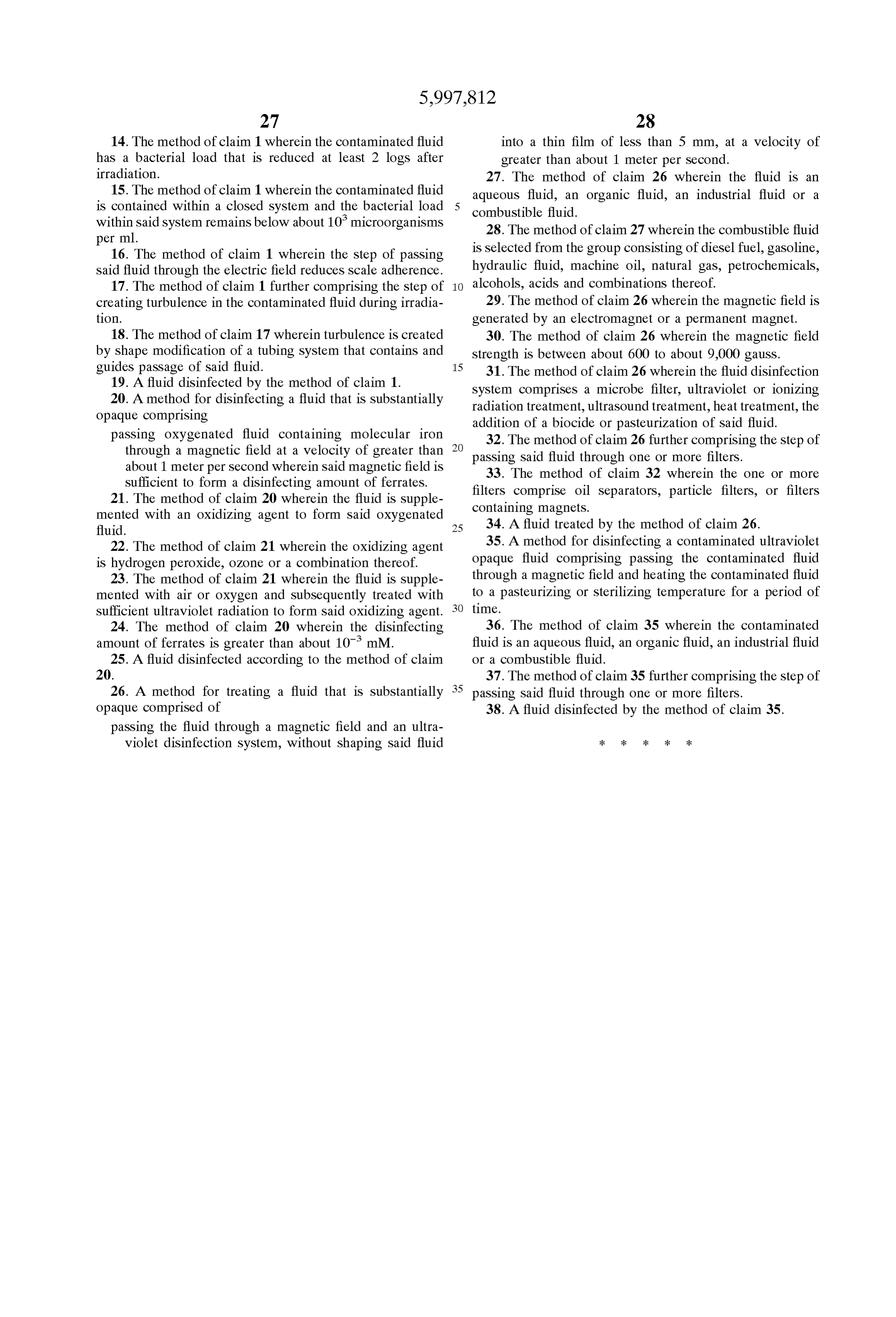
Provenance
- Collection
- Cited prior art
- Original PDF
- patentimages.storage.googleapis.com →
- Filed
- 1996-08-01
- Pages
- 27
- Method
- pdftotext (the PDF's own text layer) + pdftoppm 300dpi page scans
- Source
- Google Patents bibliographic record
- Granted
- 1999-12-07
- Inventors
- Jeffrey C. Burnham; Robert S. Reimers; Jery E. Barton; Warren S. Bankston; Coolant Treatment Systems LLC; Tulane University
- Transcribed from
- patentimages.storage.googleapis.com →