patent · US5772792A
Solar generator
30 June 1998
Page 1 — bibliographic record
United States Patent (19) 11 Patent Number: 5,772,792 Zimmermann (45) Date of Patent: Jun. 30, 1998 54). SOLAR GENERATOR 52 U.S. Cl. ............................................. 136/248; 136/246 58 Field of Search ...................................... 136/246, 248 76 Inventor: Johann Zimmermann, Santisweg 10,
D-88281 Schlier, Germany 56) References Cited 21 Appl. No.: 682,713 FOREIGN PATENT DOCUMENTS 22 PCT Filed: Nov. 21, 1995 0098897 1/1984 European Pat. Off.. 86 PCT No.: PCT/EP95/04570 Primary Examiner Nam Nguyen
Attorney, Agent, or Firm-Larson & Taylor
The invention refers to Sun generators, which at the same 87 PCT Pub. No.: WO96/18235 time deliver warm water and electrical current in the form of PCT Pub. Date: Jun. 13, 1996 direct current (DC) and alternating current (AC) and are 9 working at a large angle range to the emitting radiation and 30 Foreign Application Priority Data their color can be adapted to that of the environment and Dec. 5, 1994 DE Germany ............................ oo which will not freeze at low temperatures. (51) Int. Cl." ................................................... H01L 31/058 6 Claims, 2 Drawing Sheets
Page 2
Drawing sheet — no readable text.
Page 3
Drawing sheet — no readable text.
Page 4
SOLAR GENERATOR desired, and the left-hand side of hose 2 is omitted from FIG.
FIELD OF THE INVENTION
1) and an inner hose 3. A winding (or windings) 1 is wound around the hose 2 and (or) the inner hose 3. Winding 1
The present invention refers to Sun generators which provides a light transmitting System formed by grooves 10 generate electric current while preparing hot water at the in elements 17, and by a photovoltaic active coating 13 (only Same time. Radiation is passed through the Sun generator's partially shown in FIG. 5) thereon. A permanent or remanent layers one after the other, with the layers being non-dazzling magnetizable medium 11 circulates automatically or by and adaptable in color for the observer to match the envi force through hose 2 as shown by the circulation arrows. The ronment of use. The Sun generator can be operated over a transmission of the radiation impinging on the Sun generator large angle area (about 230 degrees) relative to the direct 30 and hence on the medium 11 or water 9 in hose 3, and on the photovoltaic coating 13, make it possible to transform radiation incoming to the active Surface thereof, and the Sun this radiation of different wavelengths into heat and current generator may possess a device against freezing. without loss. The magnetizable medium 11 is additionally in BACKGROUND OF THE INVENTION a by-pass connection to a thermosiphon System active in Till now, no Solar generators are known which present the pumps connection 15 Series 15. Resistors and including heating resistors 14 and 14 heat up the magnetizable medium 11 characteristics of the present Sun generator mentioned and indirectly the water 9 in the inner tube 3 in a heat above.
eXchange relationship. Medium 11 is moved by Such heating
In “Hybrid Solar Energy Generating System” by D. E. and/or by pumpS 15 for current generating, which is addi Soul, U.S. Pat. No. 4,700,013 of 13th Oct., 1987, a system tional to the current generated in the Sun generator by is disclosed which uses fluid-cooled Solar cells. photovoltaic coating 13. Thus, a System for induction gen Nevertheless, these cells are not cooled directly like in the eration of an efficiency rate of this height till now unknown present Sun generator, and the warmth is just received by a is provided, together with the generation of e.g. hot water holding System. and/or electrical current.
Moreover, in order to generate electric current and ther 25 The outer hose 2 and inner hose 3 of the thus integrated mal energy at the same time with Such a System as disclosed heat changer transform the radiation directly, or indirectly in the Soul patent, expensive devices Such as polarization via a System of resistances and Foucault current, in the Sun filters are required and the radiation must be divided into generator 30 of the present invention. In addition, resistors long wave and short wave radiation, whereby the efficiency 14 totally or partially are also used to protect against rate of the energy transformation is diminished. freezing of the transport medium 11 for heat eXchange and Also the devices to be employed in the Soul patent System the medium 9 in the inner tubes.
are expensive and may be Susceptible to failures, So that they The winding 1 is preferably manufactured of colorable are not Suitable for Small and maintenance-free operating plastic, or any other Suitable material Such as light trans Systems like the System of the present Sun generator. With mitting fibers. Winding 1 is a System for receiving the the present Sun generator, 40 watts of delivered photovoltaic 35 light/radiation, as well as optionally providing a base for an power is constantly produced and additionally up to 100 electrical/magnetical or other acting field. In the preferred watts of delivered thermal power have been measured. This embodiment, winding 1 is a compact System of lenses, and may be contrasted with usual Separated Solar generators is provided with all Suitable croSS Sections or thicknesses which average 25 watts of electrical/50 watts thermal power. and preferably with grooves 10, or as an energy transporting Moreover, the temperature of the present and cooled Sun 40 mechanism winding 1 can be layered/bundled. Winding 1 generator remained constant during the measuring period (6 also has an energy-transforming (photovoltaic) coating 13 as hours), whereas the temperature in the usual photovoltaic noted above e.g., doped Silicon layers, as disclosed in patent Solar generators rose while the deliverable electric power application DE 42 05721.
during measuring time diminished. In an alternative embodiment as shown in FIG. 5, the BRIEF DESCRIPTION OF THE DRAWINGS 45 winding 1 is a light transmitting fiber/energy transporter which is Surface-covered with a vaporized coating 13' of a
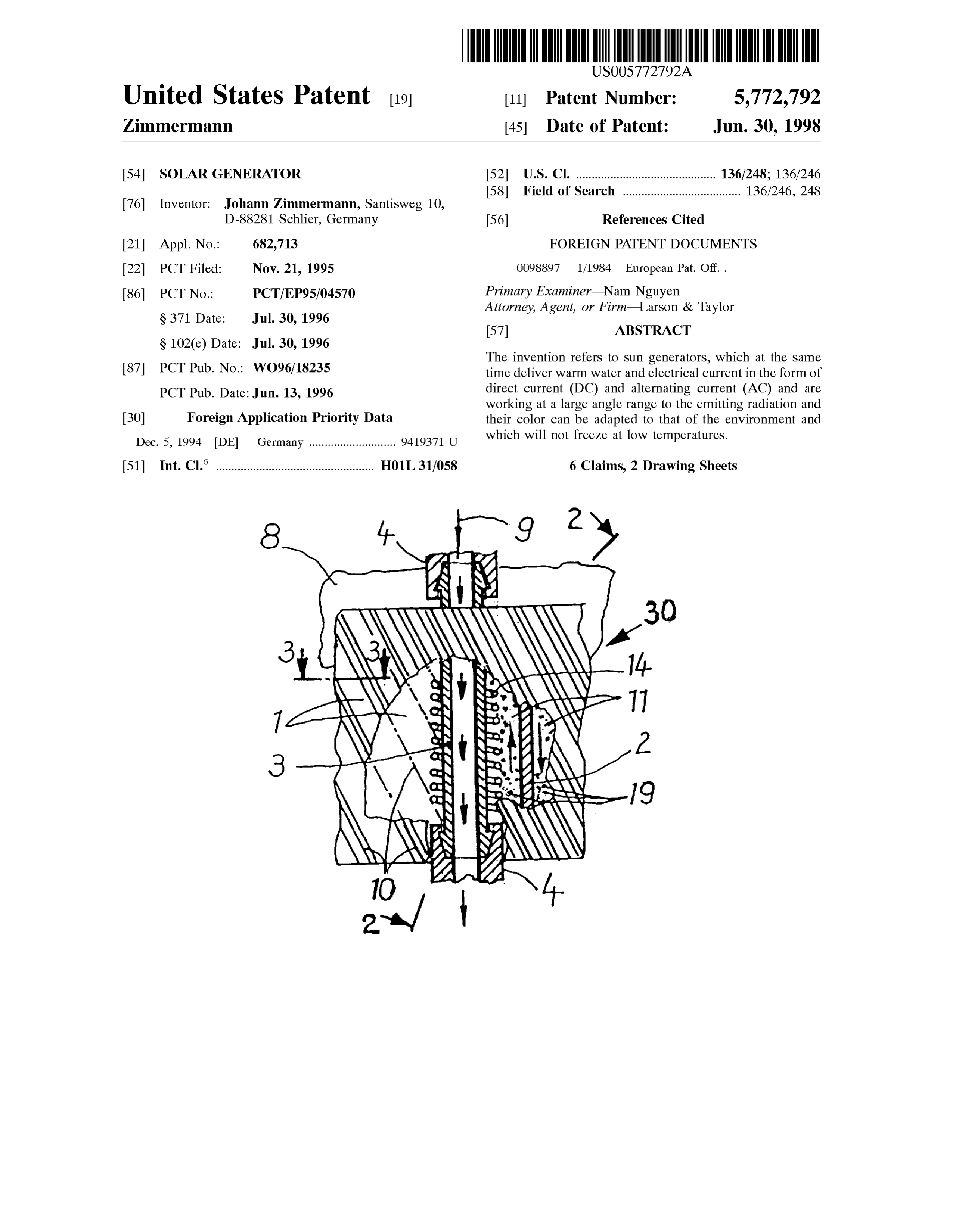
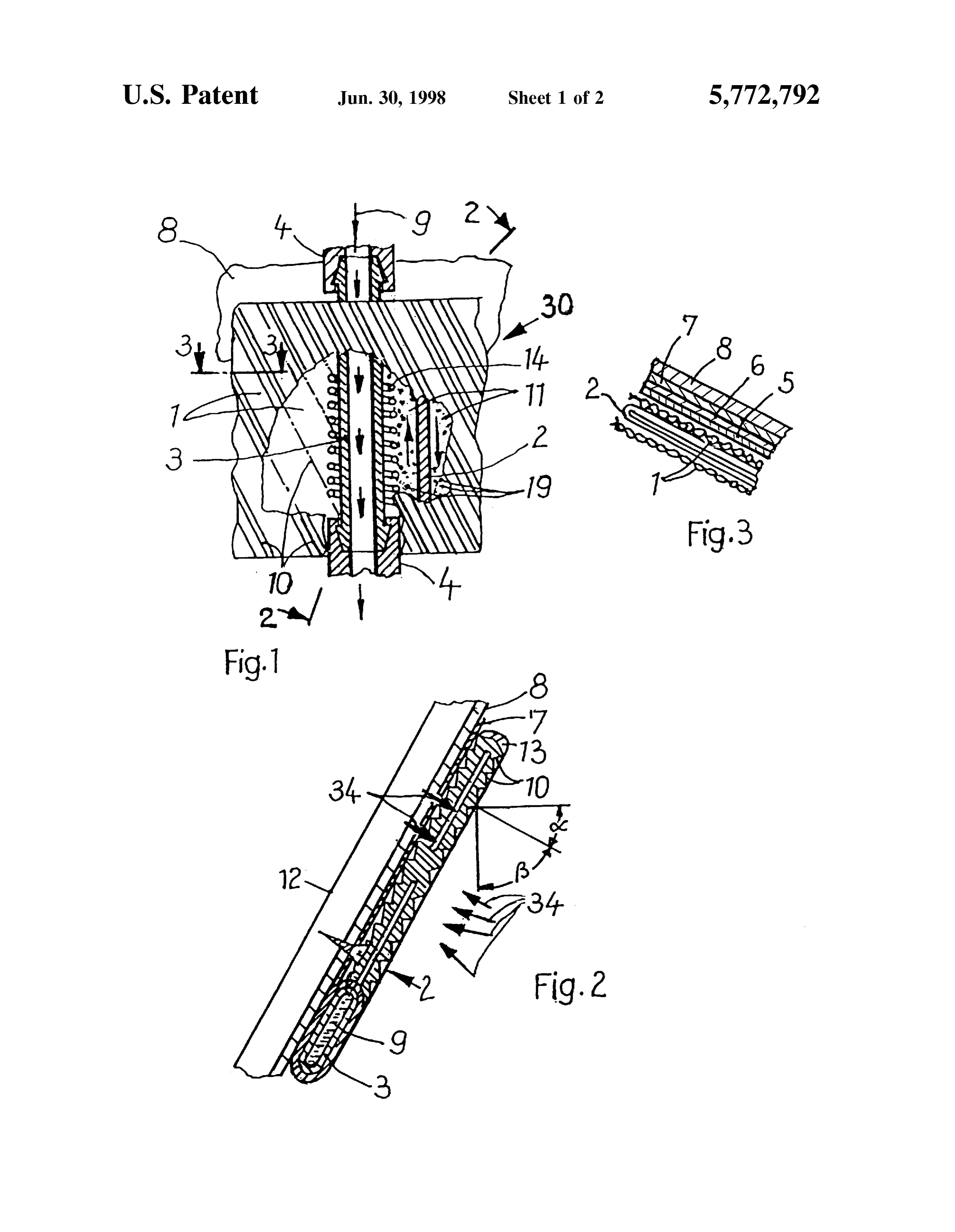
FIG. 1 is a schematic front elevation view of a Sun mixture of powdered Substances and hardening working generator according to the present invention with part of an material according to the disclosures of patent applications outer Side of a winding thereof cut away on the right-hand PCT/DE90/00891, EP 90917048.2-2309/0512998 and DE Side, and on the left-hand Side the outer Side of the winding 50 3938 881. This makes possible the combination of photo together with the underlying hose are cut away to reveal the Voltaics and thermics for obtaining of energy with the inner Side of the winding. present invention.
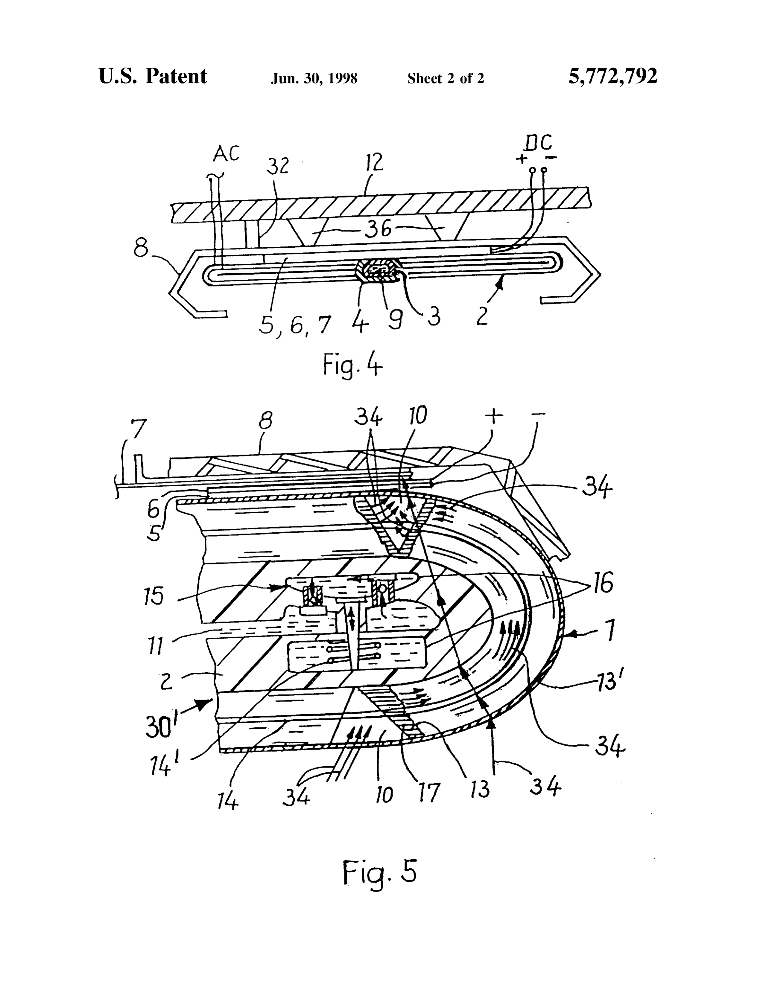
FIG. 2 is a mostly elevation Schematic Section of the Sun Preferably, the Sun generator 30 can be mounted on a generator depicted in FIG. 1 taken along the line 2-2 in house wall 12 as shown, or on house roofs or by themselves. FIG. 1. 55 However mounted, the integrated heat eXchanger intercepts FIG. 3 is a schematic section of a portion of the Sun Sun light/radiation and is heated thereby. The grooves 10 of generator depicted in FIG. 1 taken along the line 3-3 in the winding 1 around the hose 2 internally reflect or transmit FIG. 1. the Sun light/radiation from an observing angle of about -60 FIG. 4 is a Schematic top plan view of the Sun generator degrees and +60 degrees (C., f) from the normal to the depicted in FIG. 1. 60 Surface as Seen in FIG. 2. And, due to the construction of FIG. 5 is an enlarged view of a right-hand end of an winding 1 containing grooves 10 in the transparent plastic or alternative Sun generator Similar to that depicted in FIG. 4. of any Suitable material thereof, reflected light/radiation over an angle of more than e.g. itó0 degrees (for the angles
DESCRIPTION OF THE PREFERRED C. and the angles f) is transmitted onto the Surface of the EMBODIMENTS 65 hose 2 through the winding 1.
The Sun generator 30 of the present invention includes an An observer from a bird's eye perspective at an angle C. outer hose 2 (note: more than one outer hose 2 is possible if of more than approximately 30 degrees Sees the Sun gen
Page 5
erator 30 as a black surface, optically deformed by this The expanded metal 8 is a support for the hose 2, the View-point to a Smaller overall length than its actual length. Surrounding windingS 1, the inner tube 3, the connecting That means that the Sun generator's Surface which is at pieces 4, the electrical resistances (elements 5 and 6 and disposal for the adsorption of Sun radiation (i.e., the effective connection 7), and the photovoltaic coating or covering 13 Surface measured perpendicular to the impinging radiation) on the various elements 5, 6, 17, 10. The expanded metal 8 according to the Sun's position in comparison with the is screwed with screws 32 and plugs 36 on a house wall 12 largest Surface, is a height or length (at the same relative or the like and is additionally mounted with quick binding measurements of horizontal collectors/positions) which is concrete or the like (not shown) in order to keep a distance apparently Smaller. That however is without any disadvan tage as the normally existing perpendicular Surfaces on from the wall correct and for additional fastening. The inner house walls, which till now were mostly unused for that tube 3 is preferably of a harder material than the connecting pieces 4 and the hose 2, So that for fastening thereof there is purpose, can now be employed without concern for their leSS used than favorable orientation. The Sun generator 30 of this utilitythemodel adhering tightening and Sealing System known in G 9207218.6 and registered according to construction now can be adapted to all usual house wall colors, what is indispensable for esthetic reasons when using 15 PCT/EP92/01181. In that system the mandrel, here in the the Surfaces of a house which are typically perpendicular inner hose 3, opens out at each end for connection to the and unusable for esthetic reasons. Prior to this invention, no connecting pieces 4, and hence hose 3 gets pulled tighter working material or combined material was known which with increasing tension load. A light upsetting or internally reflects light depending on direction and which compression, however, is Sufficient to loosen the connection respectively can transmit partially at the Same time. made in a relatively easy way. For convenience, the light transmitting parts are hereafter In the version shown according to FIG. 1, the material called optical transmitting lenses. The frontal side of these used for the hose 2 is an elastomer thermoplastic Stable at lenses are approximately kept positioned opposed to the over 140 C. of ethylene-butylene-polystryol. This material direct direction of the Sun light, while the Outer Surface is is transparent for light and can be colored in any color. photovoltaicly active. These lenses emit radiation to the Moveover, this material is resistant to low temperatures and collector foil 13 and direct light/radiation reflecting perpen 25 can be very well welded with polypropylene. Preferably the dicularly to the main axes thereof to the foil 13 as well. By inner tube 3 uses the same material as for the hose 2, but in means of manufacturing, the winding 1 Surrounds the hose 2. The winding part mounted on the reverse (inner side) of 3order is an to obtain the necessary hardness the material of hose irradiation croSS-linked version. The winding 1 is a the hose 2, which hose 2 is flat pressed with the inner hose 3, is one or Several closely lying windings of transparent transparent polymethylmetaacrylate (PMMA), for example extruded as mass pre-material from granulate. The croSS plastic or of any other Suitable material, and has beams Section form of the winding 1 material is lens-shaped, and it impinging on its reflecting Surfaces. The lenses (acting now is thus appropriate for winding around the hose 2 in one coil as prisms—which can have also other geometrical and/or non-geometrical definable shapes) provide for reflection or 1 several. The grooves 10 can be provided in the winding before or after winding around the hoses 2, 3 or 2 and 3.
and/or light/radiation emission, or for light transmission 35 totally or partially via the System of lenses and/or the light The hose 3 is manufactured according to the procedure transporting System (via fiber bundles or light transmitters indicated in the patent application P 4142684.3 and with the 17 schematically shown as FIG. 5) to the coatings of the according and machines
tools according to G9106626.3, and further
photovoltaic elements 13, 5 and 6, and to other such ele 00891, DE 4140875 A1, G8913795.7 and DE 4201759. ments in?on the hose 2 and the winding 1. 40
After winding around, the winding 1 together with the
The circuit, like that from the delivered direct current
(DC), is generated as an alternating current (AC). A mag PCT/DE90/00891 and, as 3thearecasepressed inside formed inner tube may flat according to be, provided with netic field is provided around the expanded metal 8 of iron grooves 10.
material, or around any other remanent and/or permanent magnetizable material, e.g., elementary magnets 19 in the 45 The Sun generator 30 is mainly made of thermoplastic, mixture of glycol and water mixed in a 50:50 rate as medium which permits operation in a temperature range from about 11. The magnetic field transports finely dispersed remanent minus 70 degrees up to plus 170 degrees Celsius. According and/or permanent magnetic particles by the thermosiphon to patent application DE 4205721, there is also produced a effect. This thermosiphon effect is supported by the thermal highly Solid, radiation resistant, form Stable, printable and effect of heating resistances 14 and/or by a pumping effect 50 temperature
resistant foil covered photovoltaic elements 5, 6 of the pumps 15.
FIG. 2 shows, with arrows 34 arranged under different Lateral framework members or sparings 16 are provided angles and perpendicularly, the emission of radiation 34 with fabric inlays, which inlays minimize the expansion and from the lenses which heats the medium 11 causing it to flow have integrated therein Zones of the laminate foils. The (or by radiation 34 at any angle hitting on the Sun generator). 55 fabric inlay of this combined working material is covered by With the medium 11 flow in the magnetic field of the plastic, and electrical Spools 14 and pumpS 15 are provided expanded metal 8 (or of any other Suitable magnetic/ as shown. According to the invention, there are available electrical transmitter), there is delivered an inductive current printable plastic foils with Several coatings of the photovol (an alternating current) to the connections 7 and leads taic elements, e.g., in the high-vacuum processing, by labeled “AC. This generation of alternating current by 60 evaporating of a Silicon compound on highly flexible thin flowing of hot water at the same time is unique. The heat plastic foils of about only 0.2 mm thickness to the already eXchange from the generator to the Store or reservoir for printed connections.
warm water is realized in the Sun generator 30 of the present The laminated foils are bonded to each other by welding invention in the inner tube 3 filled with water 9 as the heat or by gluing, have about a 0.3 mm thickness, have connec flux passes through the tube wall of the hose 2 and the 65 tions 7 and inlaying electronic components, and are gas transporting medium 11 and elementary magnetic particles tight. The fluid filled tube 2 and the inner tube 3 are then surrounding the tube 3. fitted one into each other and flat pressed So that they form
Page 6
S 6 multilayer photovoltaic elements out of about 10 Single impinges thereon, which direct current produces an plastic foils with evaporated photovoltaic coating thereon active electromagnetic field in Said material; together with the coated elements 17 located in the winding a first circulating means for circulating Said Second fluid 1 which arise from the grooves 10 on the front part of the and the magnetic particles therein in Said outer tube windings 1. whereby Said magnetic particles circulating in Said The basic working material is produced from irradiation Second fluid generate an alternating current in conjunc croSS-linked plastic of e.g. a ethylene/butylene/polystyrol tion with the electromagnetic field which is applied to mixture, with the glass fiber and the covered glass fiber Said heating element to heat Said Second fluid directly fabric being rolled at the same time. The temperature and hence Said first fluid; and resistance and the working material characteristics of raising filling materials being obtained, at the same time that a Second circulating means for circulating Said first fluid calibration of the basic working material foils and the to obtain heat energy from Said first fluid and to cool laminate manufactured therefrom are produced, using e.g., a Said Second fluid.
Silicon compound material. 2. A Sun generator as claimed in claim 1: In this version, the photovoltaicly generated current is 15 wherein Said System of lenses is provided as a winding partially used to transport/circulate the elementary magnets attached about Said outer hose, Said winding including in the magnetic/magnetizable fluid 11, Supporting the ther a Series of grooves on an Outer Surface thereof. mosiphon effect by Sun irradiation with the help of the 3. A Sun generator as claimed in claim 1: membrane 15 and/or heating resistances 14 provided as wherein Said Second fluid is a liquid including an anti resistance coils around the inner tubes 3 and passing heat freeze agent therein; and indirectly to the tube 2. wherein Said magnetic particles are one of permanent or In this version the Sun generator 30 is totally only about remanent magnetic particles.
12 mm thick and can be coiled in a roll, and in coiled form 4. A Sun generator as claimed in claim 1: it can be hung on house walls and easily removed therefrom. 25 further including an expanded metal base to which Said I claim: inner hose and Said outer hose are mounted and which 1. A Sun generator comprising: is adapted for mounting on a vertical Structure. an inner tube filled with a first fluid; 5. A Sun generator as claimed in claim 1: an outer tube Surrounding Said inner tube and filled with wherein Said inner tube and Said outer tube are made from a Second fluid in which magnetic particles are a colorable thermoplastic elastomer which is transpar Suspended, said first and Second fluids being in a heat ent, and eXchange relationship; wherein Said System of lenses is made from a material an electrical heating element adjacent Said inner tube and which is colorable.
inside of Said outer tube; 6. A Sun generator as claimed in claim 1: a System of lenses located on Said outer tube, Said System 35 wherein Said System of lenses is a radiation-transporting of lenses receiving radiation and reflecting a part of the bundle of fibers; and received radiation to Said outer tube and Said inner tube wherein Said photovoltaic material is integral with Said for heating of Said first and Second fluid mediums, fibers.
a photovoltaic material integral with Said System of lenses which produces a direct current when radiation
Provenance
- Collection
- Patents citing this work
- Pages
- 6
- Method
- pdftotext (the PDF's own text layer) + pdftoppm 300dpi page scans
- Patent office record
- patents.google.com →
- Source
- Google Patents citing-documents table
- Assignee
- Zimmermann; Johann
- Inventors
- Johann Zimmermann
- Published
- 1998-06-30
- Transcribed from
- patentimages.storage.googleapis.com →