patent · US5395490
Method for treating materials by the application of electromagnetic energy at resonant absorption frequencies
7 March 1995
Page 1 — bibliographic record
United States Patent (19) 11 Patent Number: 5,395,490 Hoff et al. 45 Date of Patent: Mar. 7, 1995 54 METHOD FORTREATING MATERIALS BY Primary Examiner-John Niebling THE APPLICATION OF Assistant Examiner-Arun S. Phasge ELECTROMAGNETCENERGY AT Attorney, Agent, or Firm-Ronald S. Laurie RESONANT ABSORPTION FREQUENCIES 57 ABSTRACT 75 Inventors: Don G. Hoff, Tiburon, Calif.; Joseph A method for changing a characteristic of a material is F. Stiley, III, Spokane, Wash. provided. The characteristic of the material is deter 73) Assignee: Intertec, Ltd., Mill Valley, Calif. mined by the nature of the bond coupling certain molec ular components in the material. The material is ex 21) Appl. No.: 61,442 posed to electromagnetic energy having a frequency 22 Filed: May 14, 1993 range related to the bond coupling two molecular com ponents in the material. During the time the material is 51) int. Cl. ............................................... A45D 7/00 exposed to the electromagnetic energy, stress is applied 52 U.S. C. ................................ 204/132; 204/157.15 to the material. As a result, the bond is broken and then 58 Field of Search .................... 204/131, 132, 157.15 subsequently a different bond is formed by the simulta 56) References Cited neous application of the stress and the electromagnetic energy. The structure of the new bond is determined in
3,980,855 9/1976 Boudouris et al. .......... 219/10.55A 16 Claims, 6 Drawing Sheets
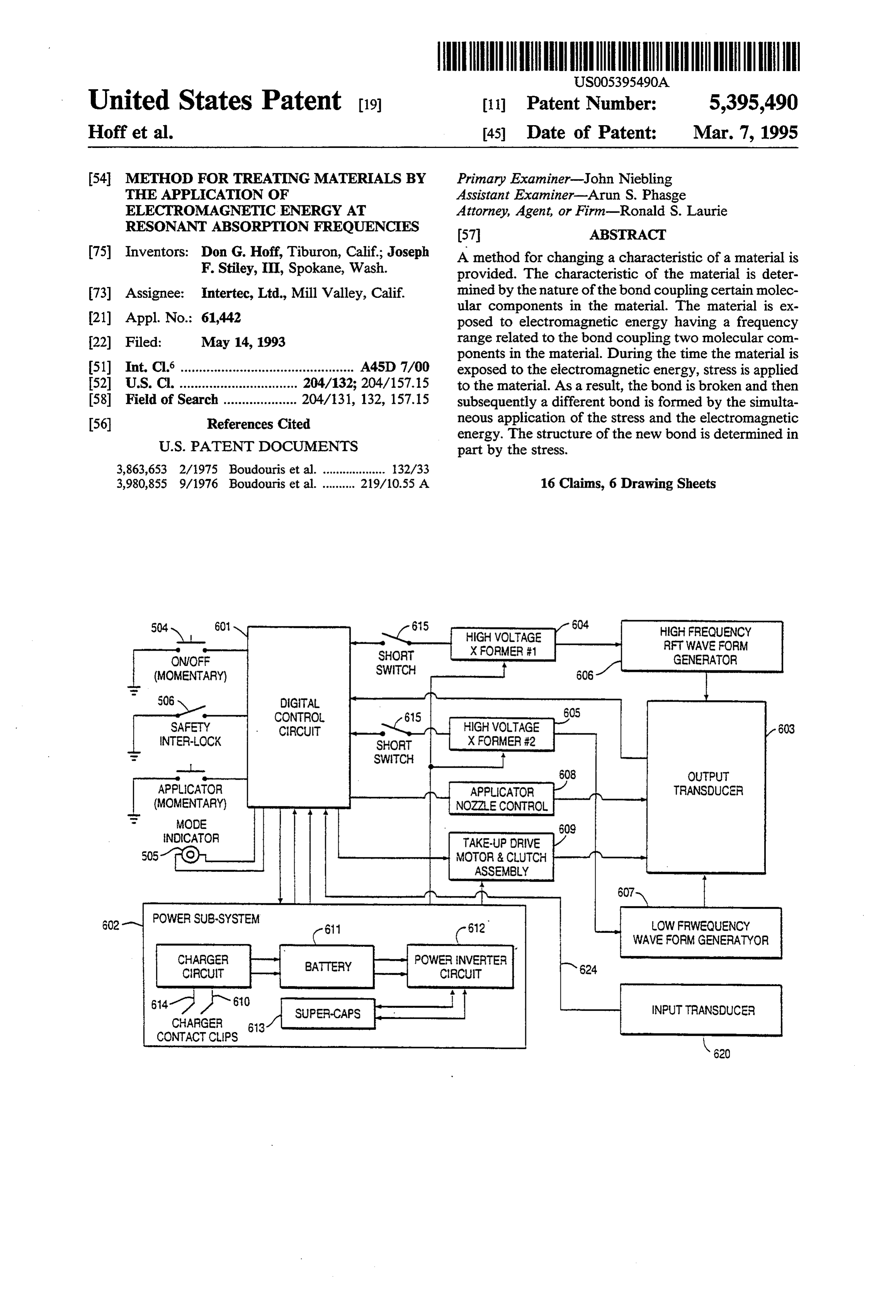
504 a 60 615 604
HIGH FRECUENCY
SHORT SSEE RFWAVE FORM
ONOFF GENERATOR (MOMENTARY) SWITCH 606
CONTROL
SAFETY CIRCUIT HIGHVOLTAGE
INTER-LOCK SHORT XFORMER #2
OUTPUT
APPLICATOR APPLICATOR TRANSDUCER (MOMENTARY) NOZALE CONTROL
MODE
ENDICATOR TAKE-UP DRIVE 5051O MOTOR & CUTCH
ASSEMBLY
OW FRWEQUENCY
WAVE FORM GENERATYOR
614-7 N6to SUPER-CAP INPUT TRANSDUCER
CONTACT CLIPS
Page 2
Drawing sheet — no readable text.
Page 3
Drawing sheet — no readable text.
Page 4
Drawing sheet — no readable text.
Page 5
H CN h ann
HCNic-N- t-CH2-S-S-H2C- EEk - Ais
N9 Disulfide Bridge c-CN-N C- NN X H C
17 %& W C- - C dC M *\ 2^ N W c
;\f-Y 'k-C-CH s-1 V RC-N-1
YaN y v 40 G -
Page 6
Drawing sheet — no readable text.
Page 7
Drawing sheet — no readable text.
Page 8
METHOD FORTREATING MATER ALS BY THE
ing chemicals, but does not avoid the cumulative ad verse effects on the hair, and the environment, caused
APPLICATION OF ELECTROMAGNETIC by these highly caustic agents.
ENERGYAT RESONANT ABSORPTION
FREQUENCIES SUMMARY OF THE INVENTION.
FIELD OF THE INVENTION The present invention eliminates the need for the use of caustic chemicals and extreme heat in permanently
The present invention relates to the treatment of altering the shape of hair by waving or straightening materials to alter one or more physical characteristics (collectively described herein as a permanent wave). or attributes by the application of electromagnetic en This is accomplished by using a process which can be ergy at the resonant frequencies of particular molecular described as resonant frequency transfer, hereinafter bonds within the material. One of the primary applica referred to as "RFT.” RFT involves the direct coupling tions of the invention involves altering the shape of of electromagnetic energy from an external source into keratinic fibers such as human hair, and is more particu the disulfide bonds within the hair shaft at the natural, larly directed to a method for permanently waving or 15 or resonant, frequencies of the bond, i.e., the frequen straightening hair without the use of caustic chemicals or uncomfortably high temperatures by exposing the cies at which energy absorption is most efficient and hair to electromagnetic energy at selected frequencies. effective. The result of this resonant energy coupling is that cleavage of the disulfide bonds occurs at a rate
BACKGROUND OF THE PRIOR ART which is more than sufficient to result in a permanent The use of chemicals in the treatment of human hair wave without the use of chemicals. Specifically, it is to achieve a "permanent wave,” or "perm,” is well estimated that a permanent wave can be effected if known. These processes typically involve the following between 5% and 20% of the disulfide bonds within the steps. First, in the “reduction' process, an acid-based hair fiber are cleaved and reformed. chemical solution is applied to the hair and the hair is 25 With the use of RFT, the reduction process, being subjected to mechanical stress by forcing the hair to electronic, is fast and clean as there is no need to apply, assume the desired new shape, e.g., by winding a lock of and thus to remove or to neutralize, such chemicals. hair around a roller, whereby the combination of me Thus the permanent wave treatment process takes chanical stress and chemical action breaks or "cleaves' much less time and is far less "messy' than with conven the disulfide bonds which link the protein molecules 30 tional methods. More importantly, the process can be within the hair and are primarily responsible for giving repeated more often than with conventional chemical the hair its natural shape. Next, the hair is rinsed to perming processes without long term damage to the remove as much of the chemical treatment solution as possible and to neutralize any solution which remains in hair, or to the environment. Because the energy is "tar the hair, thereby slowing and eventually stopping the 35 geted' to its intended purpose, i.e., disulfide bond cleav cleavage of disulfide bonds. Next, the hair is treated age, by application of a particular range of frequencies, with an oxidizing agent, such as hydrogen peroxide, it is not necessary to expose the subject to uncomfort which reconstitutes or reforms the broken disulfide ably high levels of heat generated by generalized dielec bonds in a manner which causes the hair to naturally tric heating of the hair as in the prior art. assume a new shape determined by the applied mechani 40 It is also known that the effectiveness of disulfide cal stress, and to maintain that shape after the source of bond cleavage can be accelerated by raising the temper the stress is removed. Finally, the hair is removed from ature of the water molecules within the hair shaft in the the rollers and is rinsed to remove the oxidizing agent. vicinity of the disulfide bonds. According to a preferred The chemicals used in the conventional permanent embodiment of the invention, the electromagnetic field wave treatment of hair are so caustic that if the process 45 to which the hair is exposed includes a frequency com is repeated too often over a given time period, e.g., ponent which causes the vibration of water molecules. more than twice in a year, permanent damage to the In addition to using RFT on human hair, the RFT hair will result. approach can be advantageously used in connection It is also well known that the chemical processes with other types of keratinic materials, including animal described above can be accelerated by the application 50 hair such as wool, as well as certain types of synthetic of heat to the hair mass during the chemical treatment, fibers and other polymers.
such as by placing the subject's head in a drying hood.
However, because the heat absorption characteristics of BRIEF DESCRIPTION OF THE DRAWINGS keratinic material are very poor, the process of transfer ring externally applied heat into the interior of the hair 55 pletely present
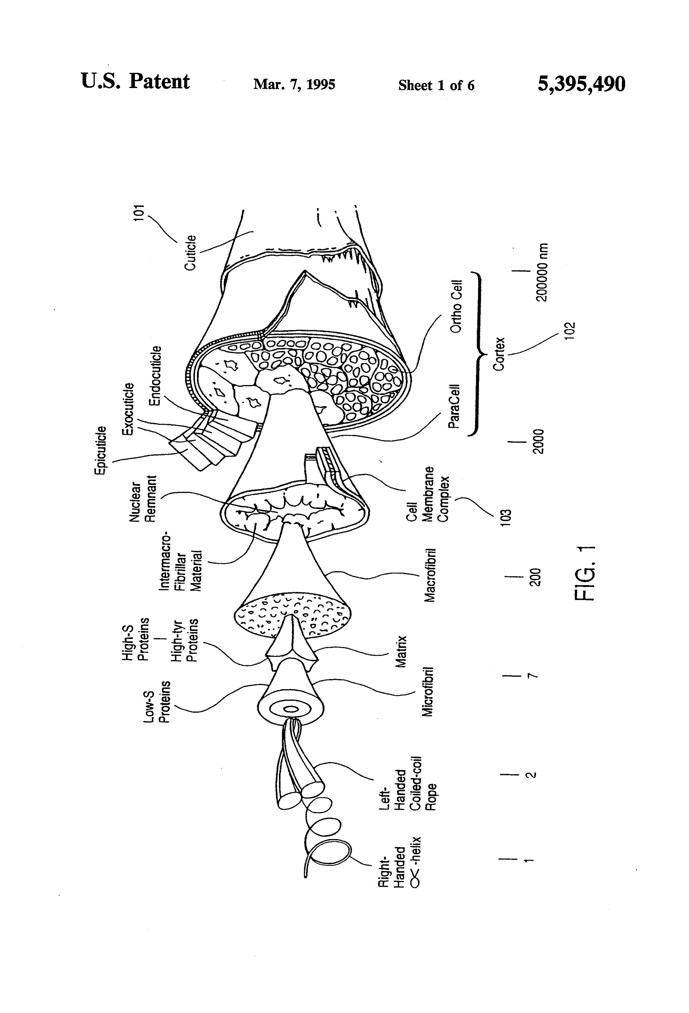
The invention will be better and more com understood by referring to the following de shaft is very inefficient and requires uncomfortably high temperatures for relatively long periods. tailed description of preferred embodiments in conjunc To solve the heat transfer problem, it has been sug tion with the attached drawings, of which: gested, in effect, to heat the hair fibers from the inside FIG. 1 is a detailed drawing of the molecular struc out rather than from the outside in by the application of 60 ture of a hair fiber;
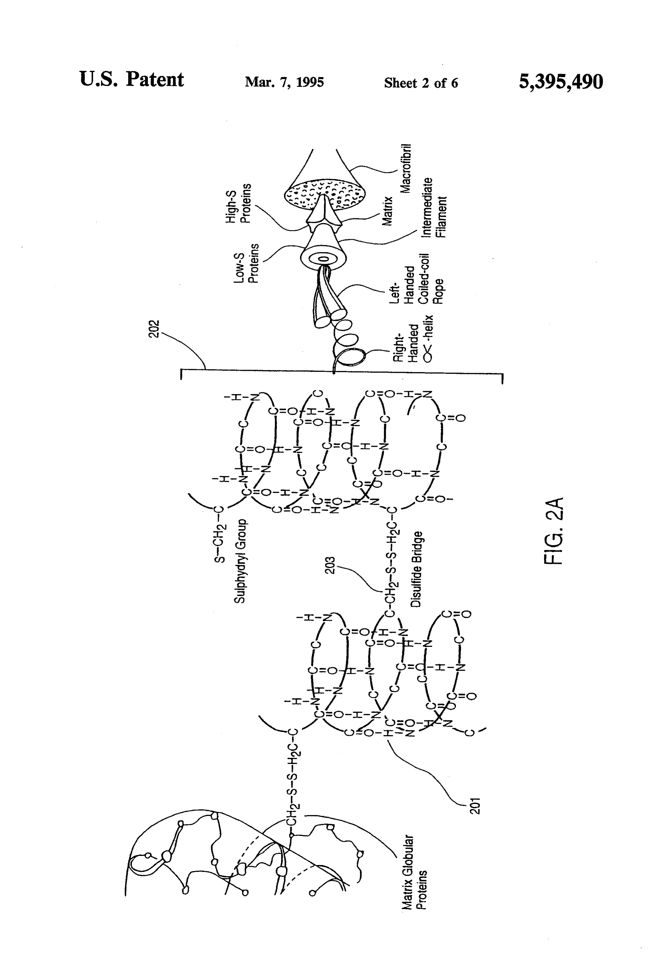
an electromagnetic field to the hair during the chemical FIG. 2A is a schematic drawing of various types of treatment. The electromagnetic field causes dielectric bonds which link protein components within the hair losses inside the hair fibers, which in turn raises the fiber;
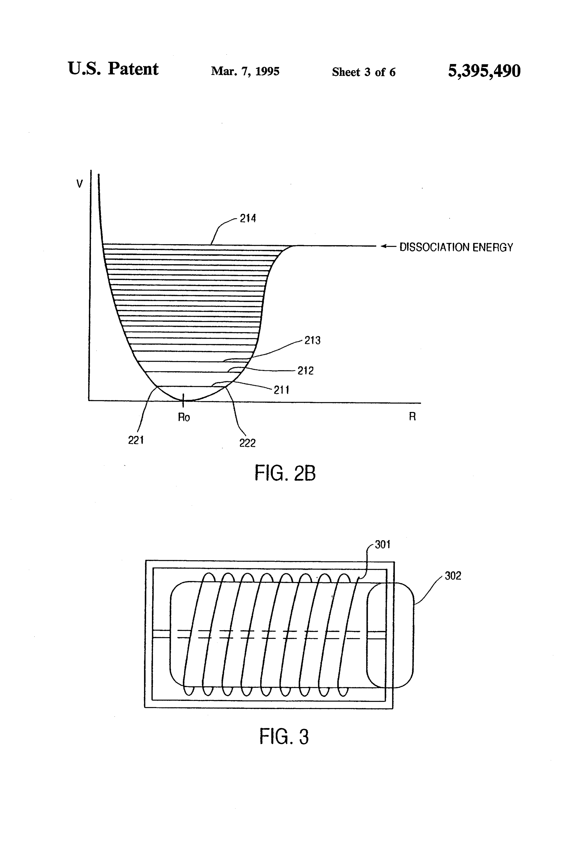
temperature of the fibers from within. One such ap FIG. 2B is an energy level diagram of a disulfide proach is described in U.S. Pat. No. 3,863,653 issued to 65 bond linking two sulfur atoms; Boudouris et al. This technique, however, merely accel FIG.3 is a drawing depicting the application of exter erates the chemical reactions, thereby reducing the time nal stress to a hair fiber by curling it around a hair roller that the hair must be exposed to the potentially damag in accordance with the present invention;
Page 9
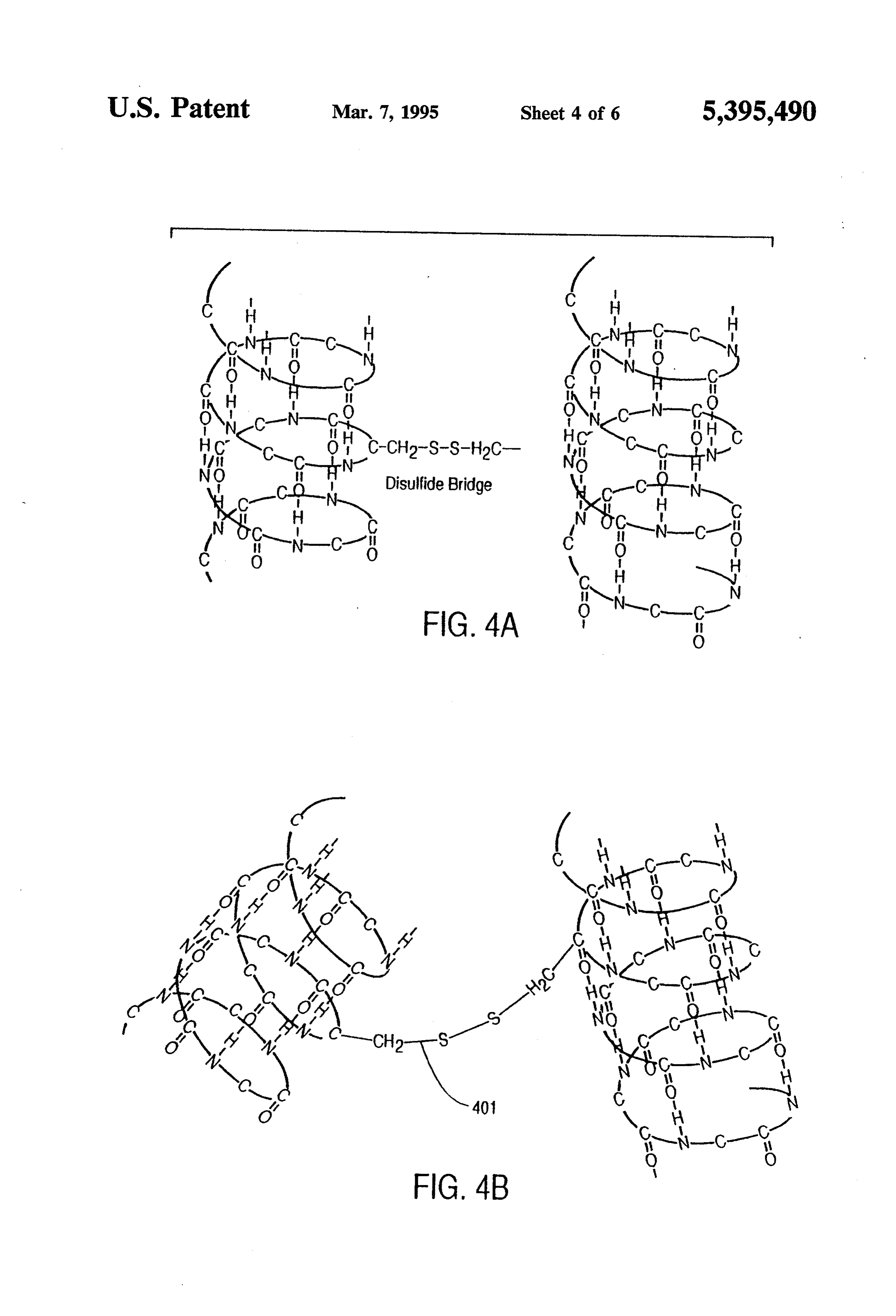
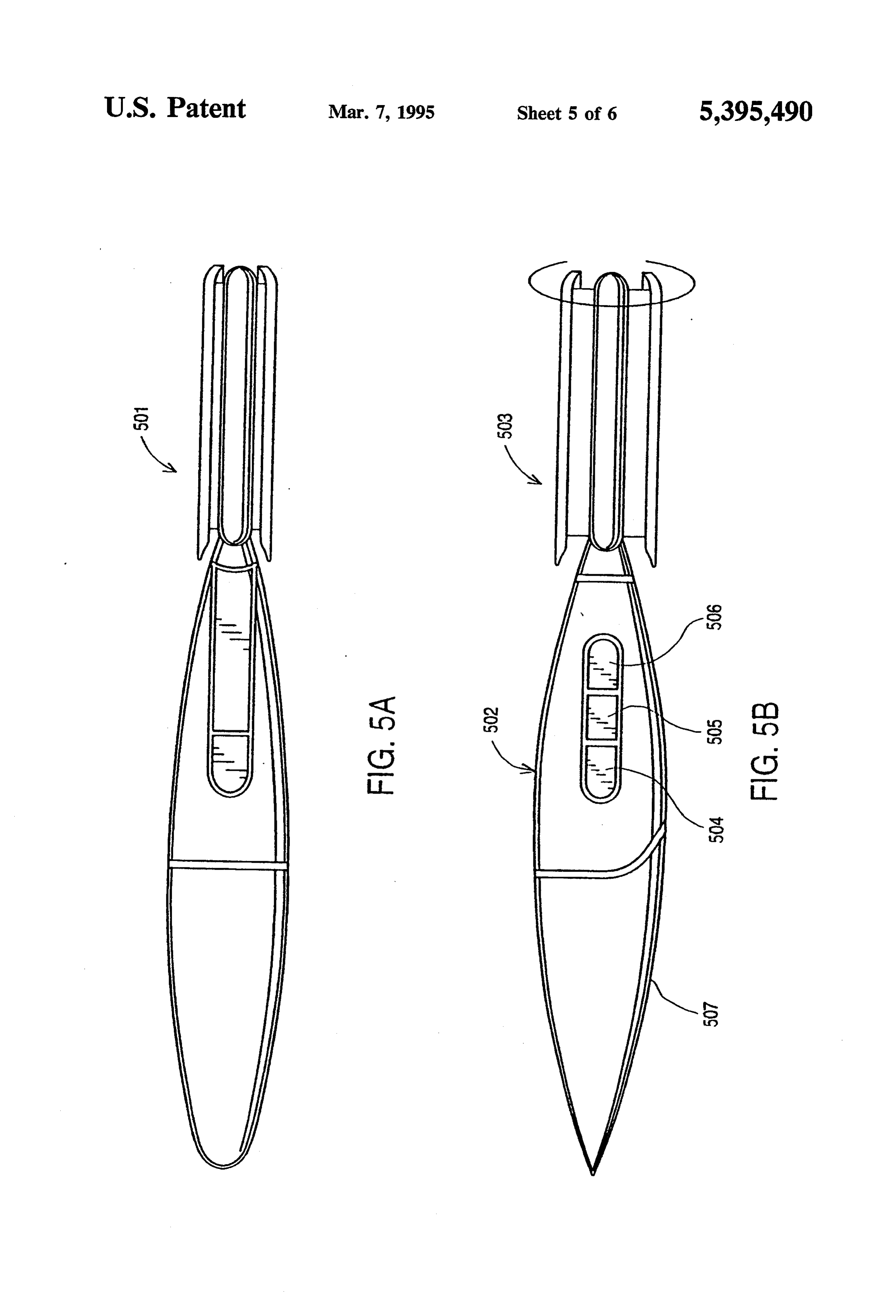
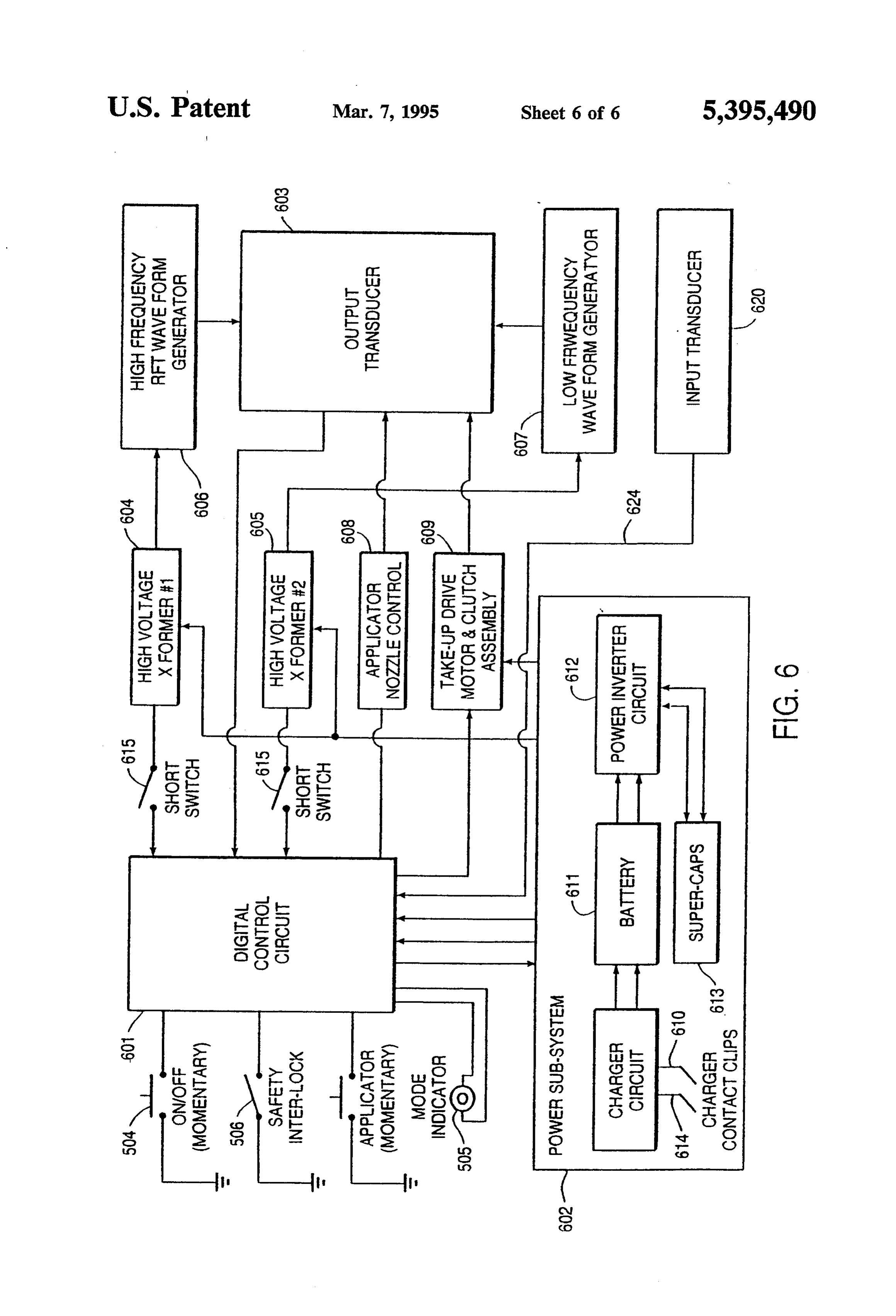
FIGS. 4A and 4B are simplified drawings of a disul distance (R) between two sulfur atoms. At any given fide bond before and after the application of mechanical time, a particular bond can only be at one of the energy stress; levels indicated by the horizontal lines, such as levels FIGS. 5A and 5B are drawings of the top and side 211, 212, and 213. That is, at each energy level, the line view, respectively, of a perming appliance useful with bounded by the parabolic-shaped curve corresponds to the RFT Method of the present invention; and the limits of vibrational extension of the bond. Thus, at FIG. 6 is a block diagram of the internal electronic energy level 211, the maximum length of the bond is components of a perming appliance in accordance with indicated by the distance between points 221 and 222. the present invention. The energy of the bond can change from one level to 10 another by absorbing or emitting a discrete amount of
DETALED DESCRIPTION OF PREFERRED
EMBODIMENTS energy. For example, when the bond absorbs an amount of energy (AE1) equal to the difference between the
The following is a description of the preferred energy at levels 212 and 211, the energy level of the method of altering the shape of keratinic fibers using bond jumps from 211 to 212. Similarly, when the bond RFT (hereinafter referred to as the “RFT Method”). 15 emits an amount of energy equal to AE1, the energy Although the RFT Method may be effectively applied level changes from 212 back to 211.
to various types of keratinic fibers, it is preferably used One way for the bond to absorb energy is by exposing to create a permanent wave in normally straight hair the bond to electromagnetic energy having a frequency fibers or to straighten normally curly hair fibers, both of determined by Planck's formula, AE =hv, where AE is which will be referred to herein as "perming' hair. The 20 the energy difference between the two energy levels, h primary advantage of the RFT Method over prior art is Planck's constant, and v is the frequency of the elec perming methods is that the RFT Method is effective tromagnetic energy. Using Planck's formula, it can be without the use of caustic chemicals or uncomfortably calculated that electromagnetic radiation having a fre high temperatures. quency of about 2*1013 hertz should be applied to a A brief discussion of the molecular structure of hair 25 disulfide bond in order to change its energy from level may be useful in understanding the efficacy of the RFT 21 to level 212.
Method. FIG. 1 shows the molecular structure of a FIG. 2B also indicates that when the bond absorbs a strand of hair. As illustrated in FIG. 1, each hair fiber sufficient amount of energy, it reaches a dissociation consists of essentially three main morphological compo energy level 214 whereupon the molecular components nents: the cuticle 101, the cortex 102, and the cell mem 30 initially attached by the bond can separate from one brane complex 103. Each cell membrane complex 103 is another and become free radicals. In order for the bond composed of a protein matrix of keratin peptide chains to move from a low energy level, such as level 211, to such as cystine. The protein components of the cell the dissociation energy level 214, a number of discrete membrane complex 103 are linked by bonds known as quantum jumps need to take place. According to disulfide bonds. The natural shape of the hair fiber is 35 Planck's formula, each of these quantum jumps has an controlled by the orientation of the disulfide bonds associated frequency. As a result, in order to achieve which link the protein chains. FIG. 2A is a schematic cleavage, the bond must be exposed to electromagnetic drawing of the various types of linkages that contribute energy having a range of frequencies which will excite to the structural integrity of the hair fiber, including the appropriate percentage of disulfide bonds (at vari hydrogen bonds 201, helical sulfhydryl groups 202, and 40 ous energy levels) to their dissociation energy level. For disulfide bonds 203. The disulfide bonds 203 between the simplified case of an isolated S2 molecule, the fre the sulfhydryl groups 202 are believed to be the primary quencies which correspond to the various quantum mechanism that establishes the structural stability of jumps are between 2*1013 hertz and 1*1015 hertz. Be hair and imparts its natural shape. cause the sulfur atoms in hair are also bonded to many Alteration of the disulfide bonds 203 is necessary to 45 other atoms, and the molecule is in a solid form, the achieve long term structural changes in the shape of preferred frequency range of the electromagnetic en hair. Conditions that do not cause the cleavage and ergy used for perming hair is between 1*1013hertz and reformation of disulfide bonds 203 will only result in 2*1015 hertz.
temporary changes. For example, the use of heat and It has been observed that coupling electromagnetic moisture to style hair may create temporary waving of 50 energy to the bond is not sufficient by itself to raise the the hair; however, the styled hair will return to its natu energy of the bond to the dissociation level. It is be ral shape after a short period of time as a result of expo lieved that this is because the electromagnetic energy is sure to moisture in the air. This is because use of heat rapidly transferred to the neighboring atoms of the and moisture to style hair merely breaks and reforms the protein components attached by the bond, thereby re hydrogen bonds 201. The newly formed hydrogen 55 sulting in the heating of the hair instead of effectuating bonds 201 are insufficient to hold the shape of hair for a the desired quantum jumps. An excess amount of heat significant period of time because the stronger disulfide could break up the molecular structure of the protein bonds 203 eventually force the styled hair to reassume matrices, thereby producing a detrimental effect on the its original shape. Thus, a permanent change in the hair. On the other hand, the normal mechanical stress shape of hair may be achieved only by cleaving and 60 produced by winding hair around a typical hair roller, reforming the disulfide bonds 203. when combined with the application of electromagnetic It is well known that the state of a bond, such as the energy at the appropriate resonant frequencies, is suffi disulfide bond linking protein chains in hair, is governed cient to achieve cleavage of a sufficient number of disul by the laws of quantum mechanics, and that the energy fide bonds to permanently alter the shape of the hair. of the bond can only exist at discrete energy levels. One of the advantages of cleaving disulfide bonds by FIG. 2B is an energy level diagram wherein the vertical electronic rather than chemical means is that the cleav axis corresponds to the potential energy (V) of a disul ing process can be instantly terminated at any time by fide bond and the horizontal axis corresponds to the turning off the source of electromagnetic energy. The
Page 10
bonds in a high energy level state will return to a low sufficient temperature to accelerate the cleaving of the energy level automatically by emitting energy. In con disulfide bonds without destroying the structure of the trast, prior art cleaving methods using chemicals cannot protein components. Unlike the heating process in con be easily and quickly terminated once the chemicals ventional hair perming methods, RFT electromagnetic have been applied to the hair. energy generates thermal energy on a localized level The preferred method of perming hair using RFT rather that heating the hair mass generally. This local typically involves three distinct stages: (1) the stress ized thermal effect increases the fluidity and plasticity initiation stage, (2) the RFT application stage, and (3) of the hair components and the rate of sulfhydryl-disul the reconfiguration stage. fide exchange. Ultimately, the induced thermal effect The stress initiation stage involves the mechanical 10 facilitates and accelerates the reformation of new disul pre-stressing of the disulfide bonds 203 to facilitate fide bonds in stress-free states.
cleavage of the bonds. Once applied, this mechanical The effectiveness of the disulfide bond cleavage can stress is preferably maintained during the entire RFT be accelerated by increasing the temperature of the Method. A curling iron or a plurality of hair rollers are water molecules in the vicinity of the disulfide bonds. typically used to apply mechanical stress to hair. FIG.3 15 The RFT electromagnetic energy may also be used to shows a strand of hair 301 rolled around a typical hair increase the thermal energy of these water molecules by roller 302. As the hair is rolled around the roller, exter including a frequency component of approximately nal stress is placed on various parts of the strand. The 2450 Mhz. The water molecules that are heated may be external stress, in turn, creates internal stresses on the either water molecules independently absorbed by the disulfide bonds which link the protein components in 20 hair fibers or the water molecules within protein helices the hair fibers. FIGS. 4A and 4B are a simplified illus (hydrogen-bonded water).
trations of the state of the disulfide bonds before and Unlike conventional methods of cleaving disulfide after the internal stress is applied. bonds, the RFT Method does not require the use of The application of mechanical stress plays an impor chemicals or generalized thermal effects to cleave the tant role in determining the shape of hair. The disulfide 25 bonds. Whereas the conventional methods employ a bonds which are subjected to the most stress will likely chemical solution treatment to cleave and reform disul be the bonds that will cleave upon exposure to electro fide bonds, the RFT Method can accomplish disulfide magnetic energy. In contrast, disulfide bonds which bond cleavage process more efficiently and more effec remain in a relatively unstressed state are less likely to tively because, being electronic, it accomplishes the be broken by electromagnetic energy. In effect, the 30 cleaving process in less time than is required using con application of mechanical stress accelerates the cleaving ventional perming methods and avoids the cumulative of those disulfide bonds which must be broken to re adverse effects on the hair fibers which can result from form the shape of the hair and leaves other disulfide exposure to caustic chemicals.
bonds intact. Following the cleavage of these disulfide Although the cleaving process using conventional bonds, new disulfide bonds, linking either the same 35 methods may be accelerated by the external application molecular components as those linked by the original of heat to the hair during chemical treatment, such disulfide bonds or different molecular components, are generalized application of heat exposes the scalp and formed in stress-free positions and cause the hair to head to uncomfortably high temperatures for relatively permanently adopt a new shape. long periods of time. The RFT Method avoids the need Following the application of mechanical stress during for generalized heating of the hair mass because it relies the stress initiation stage, the RFT application stage is on the coupling of electromagnetic energy at the natu commenced to effect cleavage of the disulfide bonds. ral resonant frequency of the disulfide bonds. Heat gen The RFT application stage involves the direct coupling erated during the RFT Method results mainly from the of electromagnetic energy ("RFT electromagnetic en localized heating of the water molecules in the vicinity ergy') from an external source into the disulfide bonds 45 of the disulfide bonds in order to accelerate the cleaving at the natural or resonant frequency of the bonds in process. Thus, a person using the RFT Method does not order to cleave the bonds. The term resonant fre experience the type of uncomfortably high tempera quency, as used herein, and in the appended claims, is tures which characterize conventional perming meth defined as that frequency, or series or combination of ods.
frequencies which, when coupled to selected molecular 50 The RFT Method also has distinct advantages over links, such as the disulfide bonds linking protein mole other methods that employ electromagnetic waves to cules in hair, causes the dissociation of the molecules by accelerate chemical perming processes. For instance, cleavage of the link. The cleaving of the disulfide bonds the method described in U.S. Pat. No. 3,863,653 issued serves to relieve the internal stress on the bonds im to Boudouris et al. teaches the use of electromagnetic posed by the external mechanical forces. 55 energy not as the means to cleave the disulfide bonds by A multi-frequency electromagnetic wave generator is direct coupling at the resonant frequency of the bonds, the preferred external source used to generate RFT but rather as a means of raising the overall temperature electromagnetic energy at the natural resonant fre of the hair fibers. Under that method, electromagnetic quency of the disulfide bonds. The application of RFT waves are applied to the hair to cause dielectric losses electromagnetic energy to the disulfide bonds creates 60 inside the hair fibers. The dielectric losses heat the hair standing waves at the resonant frequency. As the ampli fibers from the inside and thereby accelerate the chemi tude of the standing waves increases, physical deforma cal treatment. In contrast, the RFT Method employs tion of the disulfide bonds occurs. Ultimately, the RFT electromagnetic waves at specific and predetermined electromagnetic energy causes the disulfide bonds frequencies corresponding to the natural resonant fre under the most stress to cleave. 65 quency of the disulfide bonds to cleave the bonds rather The amount of RFT electromagnetic energy is pref. than to generate internal heating through dielectric erably controlled such that the temperature of the disul losses. The RFT Method also does not require chemi fide bonds is kept slightly below 70° C., which is a cals to cleave the disulfide bonds and thus eliminates the
Page 11
cumulative adverse effects of the caustic chemicals A/C electrical current to various components, includ required with prior art electromagnetic energy methods ing electronic control circuit 601, high voltage trans that rely on dielectric losses. formers 604 and 605 and take-up drive motor and clutch Once the disulfide bonds have been cleaved, the re assembly 609. Charger circuit 610 receives alternating configuration stage is initiated to form new disulfide current (NC) electrical power via the charger contact bonds. The cleavage of the stressed disulfide bonds clips 614 from an external electrical source (such as a during the RFT application stage generates free-stand common household electrical outlet). Charger circuit ing sulfhydryl groups. At this stage, water molecules 610 converts the alternating current (NC) electrical present in the hair or externally applied act to accelerate power to direct current (D/C) electrical power and the reformation of disulfide bonds. The sulfhydryl 10 stores it in battery 611. As electrical power is required groups react with disulfide molecules to form new by the components of curling device 501, power in stress-free disulfide bonds. The orientation of these verter circuit 612 converts the D/C power from battery disulfide bonds is dependent upon the mechanical stress 611 back into NC power and transfers, it to super applied to the hair fiber. New disulfide bonds are capacitor 613. Charged super-capacitor 613 supplies formed in positions which result in the lowest bond 15 A/C power to components of curling device 501 in StreSSeS. accordance with instructions from electronic control To complete the reconfiguration stage, the external circuit 601.
mechanical stress is removed from the hair fibers. At The following is a description of the functions of this time, the reconfigured disulfide bonds within each various components of curling device 501 during the hair fiber will be in a relaxed state. The net result of the 20 three stages of the RFT Method. RFT Method is a new permanent shape to the hair. During the stress initiation stage, electronic control FIGS. 5A and 5B are a top view and a side view, circuit 601 engages take-up drive motor and clutch respectively, of a perming appliance useful with the assembly 609, which in turn activates variable diameter RFT method, specifically, a variable diameter curling shaft 503. The functions of shaft 503 are to grasp and device 501. Curling device 501 has external compo 25 retain a lock of hair in a curl shape during the RFT nents, consisting of a housing unit 502, a variable diame Method and thereafter release the hair upon completion ter shaft 503, an on/off switch 504, a mode indicator of the RFT Method. Shaft 503 can be adjusted to vary 505, a safety interlock 506 and a reservoir 507. In addi the size of curls by enlarging or reducing the diameter tion, curling device 501 preferably contains control of the shaft and thus serves as the tool used to apply system components located inside the housing unit 502 30 external stress on hair fibers during the stress initiation as described below. stage of the RFT Method.
FIG. 6 is a block diagram showing the internal elec In the RFT application stage, electronic control cir tronic components of curling device 501. These include cuit 601 initiates the process by engaging power subsys an electronic control circuit 601, a power subsystem tem. 602 to provide NC electrical power to high voltage 602, a signal transducer 603, a pair of high voltage trans 35 transformers 604 and 605. Upon receipt of electrical formers, 604 and 605, a high frequency RFT wave form power, high voltage transformer 1604 generates ap generator 606, a low frequency wave form generator proximately 2000 VAC and supplies it to high fre 607, an applicator nozzle control 608, and a take-up quency RFT wave form generator 606. Similarly, high drive motor and clutch assembly 609. voltage transformer 2 605 accepts electrical current Electronic control circuit 601 acts as the control from power subsystem 602 and converts it into approxi center for curling device 501 by monitoring and con mately 100 VAC. The 100VAC is then supplied to low trolling the operation of its various components. More frequency wave form generator 607. A short switch 615 specifically, curling device 501 is enabled or disabled by is connected to each of the high voltage transformers to electronic control circuit 601 in accordance with the detect short circuits. A signal is sent to electronic con status of on/off switch 504. Activation of switch 504 45 trol circuit 601 to disable curling device 501 upon detec initiates the operation of curling device. If switch 504 is tion of a short circuit in the circuits of either of the high activated while curling device is already in operation, voltage transformers.
electronic control circuit 601 will suspend operation. As high frequency RFT wave form generator 606 Thereafter, electronic control circuit 601 resumes oper receives the 2000 VAC from high voltage transformer ation of curling device if switch 504 is again activated 50 604, it generates RFT electromagnetic waves at various by a coded reset sequence, e.g., a series of four ON and frequencies spanning frequency range of 2*1013 Hz to OFF operations, and/or after a predetermined time 1*1015 Hz (corresponding to the natural resonant fre interval, for example, one minute, in order to avoid quency of disulfide bonds) and also a frequency of 2450 accidental reactivation of the cleaving process; other Mhz, which is the resonant frequency of the water wise, the operation of curling device remains termi 55 molecules. These RFT signals are transmitted to signal nated. Electronic control circuit 601 is grounded transducer 603 (containing within curling device 501) through safety interlock 506 by means of which the which applies the RFT electromagnetic energy to the curling device may be disabled. hair fibers to cleave disulfide bonds. At all times during the RFT Method, the state of Similarly, low frequency wave form generator 607 curling device 501 is indicated by mode indicator 505. 60 uses the 100VAC output from high voltage transformer Mode indicator 505 is a light that illuminates when the 2605 to produce electromagnetic signals having a fre curling device is in operation. Moreover, mode indica quency of approximately 30 Hz. These electromagnetic tor 505 flashes intermittently when the operation of the signals are also transmitted to signal transducer 603. curling device is temporarily suspended. The 30 Hz electromagnetic signal is designed to transfer Curling device 501 is powered by the power subsys 65 vibrational energy to the hair and thus provide addi tem. 602, which preferably comprises a charger circuit tional stress on the disulfide bonds to aid and enhance 610, a battery 611, a power inverter circuit 612 and a the cleaving of the disulfide bonds by the RFT electro super capacitor 613. The power subsystem provides magnetic energy.
Page 12
Curling device 501 preferably also contains at least 2. The method of claim 1 wherein said frequency one input transducer 620 for monitoring one or more range corresponds to the resonant frequency of said physical attributes of the hair such as temperature or bond.
reflectivity. The output of input transducer 620 is sup 3. The method of claim 1 wherein said bond couples plied to electronic control circuit 601 via line 624. Elec said first molecular component with a second molecular tronic control circuit 601 uses these signals to imple component and wherein said reformed bond couples said ment a feedback control system. For example, during first molecular component with a third molecular the RFT application stage, athermostat (which is a type component. 4. The method of claim 1 wherein said material is of input transducer) can be used to monitor the thermal 10 hair, said bond couples said first molecular component effects of the RFT electromagnetic energy on the hair.
Upon detecting the desired effect, the thermostat sig with a second molecular component in a first orienta tion, said reformed bond couples said first molecular nals electronic control circuit 601 to end the RFT appli component with said second molecular component in a cation stage, and to proceed with the reconfiguration Second orientation, and said characteristic is the shape stage of the RFT Method. 15 of the hair, said shape having a first form determined by Other examples of input transducers are optical or infra-red sensors. These sensors measure changes in the said first molecular orientation and said shape having a optical or infra-red spectra resulting from changes in second entation.
form determined by said second molecular ori the reflectivity of hair during the RFT processes. The 5. The method of claim 1 wherein said material com results of these measurements can be supplied to elec 20 prises protein.
tronic control circuit 601 as additional parameters to the 6. The method of claim 5 wherein said material com feedback control system.
Optionally, in the reconfiguration stage, electronic prises cystine.
7. The method of claim 6 wherein said material com control circuit 601 may also activate applicator nozzle prises animal hair.
control 608 which draws water from reservoir 507 and 8. The method of claim 7 wherein said material com dispenses a water mist through signal transducer 603 25 prises human hair.
onto the hair fibers. The water molecules facilitate reac 9. The method of claim 7 wherein said material com tions between the disulfide molecules and the sulfhydryl prises wool.
groups to form new disulfide bonds. Again, the thermo 10. The method of claim 1 wherein said material stat monitors the hair fibers to determine whether the comprises a polymer.
desired effects have been achieved. Upon receiving 30 11. The method of claim 10 wherein said material confirmation of the desired effects from the thermostat, comprises a synthetic fiber. electronic control circuit 601 instructs variable diame 12. The method of claim 1 wherein said material ter shaft 503 to release the hair fibers from the curl contains water molecules and wherein said electromag position. At the completion of the reconfiguration netic energy includes a frequency which increases the stage, the hair will have taken on a new shape. 35 thermal energy of said water molecules. Variable diameter curling device 501 is a preferred 13. The method of claim 1 further comprising the step embodiment of the present invention; however, the of adding water to said material for facilitating the for RFT Method may be implemented by various other mation of said reformed bond.
apparatus, as will be readily apparent to those skilled in 14. A method for changing a characteristic of a mate the art. rial, said characteristic being determined by the nature Although specific embodiments of the present inven of the bond coupling certain molecular components, tion have been shown and described, it will be under said method comprising the steps of:
stood that various modifications may be made without exposing said material to electromagnetic energy departing from the scope and spirit of this invention. having a frequency range related to the bond cou For example, although the RFT Method is preferably 45 pling a first molecular component with at least one used to perm or straighten hair fibers, the RFT Method other molecular component, said frequency range also may be adapted to treat various other type of kera having a value above 1 x 10¹³hertz, and tinic fibers, such as wool, and may even be used to alter applying stress to said molecular components and the shape or other characteristics of synthetic fibers and said bond during the time that said material is ex polymers generally. 50 posed to said electromagnetic energy, said bond What is claimed is: being broken by the simultaneous application of 1. A method for changing a characteristic of a mate said electromagnetic energy and said stress and rial, said characteristic being determined by the nature said broken bond being subsequently reformed, of the bond coupling certain molecular components, based at least in part on said stress, to create a said method comprising the steps of: 55 different coupling between said first molecular exposing said material to electromagnetic energy component and at least one other molecular com having a frequency range related to the bond cou ponent.
pling a first molecular component with at least one range 15. The method of claim 14 wherein said frequency other molecular component; and is between 1*1013hertz and 2*1015 hertz.
16. The method of claim 14 wherein said material is applying stress to said molecular components and 60 hair, said bond is a disulfide bond coupling said first said bond during the time that said material is ex molecular component with a second molecular compo posed to said electromagnetic energy, said bond nent in a first orientation, said reformed bond couples being broken by the simultaneous application of said first molecular component with said second molec said electromagnetic energy and said stress and ular component in a second orientation, and said char said broken bond being subsequently reformed, acteristic is the Shape of the hair, said shape having a based at least in part on said stress, to create a first form determined by said first molecular orientation different coupling between said first molecular and said shape having a second form determined by said component and at least one other molecular com second molecular orientation.
ponent.
Provenance
- Collection
- Cited prior art
- Original PDF
- patentimages.storage.googleapis.com →
- Filed
- 1993-05-14
- Pages
- 12
- Method
- pdftotext (the PDF's own text layer) + pdftoppm 300dpi page scans
- Source
- Google Patents bibliographic record
- Granted
- 1995-03-07
- Inventors
- Don G. Hoff; Joseph F. Stiley, III; Intertec Ltd
- Transcribed from
- patentimages.storage.googleapis.com →