patent · US5238546
Method and apparatus for vaporizing materials by plasma arc discharge
24 August 1993
Page 1 — bibliographic record
United States Patent (19) 11) Patent Number: 5,238,546 Bergmann et al. 45 Date of Patent: Aug. 24, 1993 (54) METHOD AND APPARATUS FOR (56) References Cited WAPORIZING MATER ALS BY PLASMA U.S. PATENT DOCUMENTS
ARC DSCHARGE
3,793,179 2/1974 Sablev et al. ................... 204/298.41 75) Inventors: Erich Bergmann, Mels; Helmut 4,197,175 4/1980 Moll et al................... 204/298.41 X Rudigier, Bad Ragaz, both of 4,448,802 5/1984 Buhl et al. .................. 204/298.4 X Switzerland 4,620,913 11/1986 Bergman ... 204/298.41 X 4,740,386 4/1988 Cheung .............................. 427/53.1 4,919,968 4/1990 Buhl et al...... . 204/297.41 X (73) Assignee: Balzers Aktiengesellschaft, 4,987,007 1/1991 Wagal et al........................ 427/53.1 Furstentum, Liechtenstein
FOREIGN PATENT DOCUMENTS
(21) Appl. No.: 935,639 257451 6/1988 Fed. Rep. of
(22) Filed: Aug. 25, 1992 3801957 11/1988 Fed. Rep. of
267464 11/1987 Japan .............................. 204/298.41
Related U.S. Application Data (63) Continuation of Ser. No. 661,545, Feb. 26, 1991, aban Primary Examiner-Nam Nguyen doned. Attorney, Agent, or Firm-Notaro & Michalos
(30) Foreign Application Priority Data In order to ignite a vaporizing arc on a target which Mar. 1, 1990 (DE Fed. Rep. of Germany ....... 4006.456 includes at least at its surface a material of a high melt Mar. 1, 1990 (DE) Fed. Rep. of Germany ....... 4006.458 ing point to be vaporized, and to stabilize and guide same, an electron beam gun or a laser is forseen for 51) Int. Cl. .............................................. C23C 14/22 generating of a local vapor cloud or a premelted spot on 52) U.S. Cl. .......................... 204/192.38; 204/298.41; the surface of the target in order to therewith ignite and
58) Field of Search ...................... 204/192.38, 298.41;
427/37, 38,572, 580,596; 118/723, 724 16 Claims, 2 Drawing Sheets
NNN
Page 2
Drawing sheet — no readable text.
Page 3
Drawing sheet — no readable text.
Page 4
also by an arranging of arc limiting means to prevent
METHOD AND APPARATUS FORWAPORZNG the arc spot from straying, whereby here additionally MATERAS BY PLASMA ARC OSCHARGE the spot shall incorporate a controlled movement on the cathode by mounting a source of a magnetic field. Due
This application is a continuation of application Ser. 5 to the pulsed generation of the magnetic field and de No. 07/661,545, filed Feb. 26, 1991, abandoned. pending on its polarity the spot is caused to move BACKGROUND OF THE INVENTION toward or away from the magnetic field. This is only a relatively directional, but not a basic guiding of the spot 1. Field of the Invention such that-albeit somewhat reduced-the danger of a The present invention relates to an apparatus for 10 local overheating and accordingly a sputtering is not vaporizing a material at vacuum conditions by means of completely obviated. Also, no successful realization of an arc with a target which includes at least at a part of such a system has been achieved. its surface a material to be vaporized. The discharge is In the DE-OS 33 45 493 a straying of the spot is again made to proceed in an area where a substantial part of prevented by means of arranging a limiting ring at the the arc current flows mostly through small spots at the 15 cathode, but without an influencing of the random surface of the target. The invention also includes an movement of the spot of the arc. Also the DE-PS 33 45 apparatus for igniting the vaporizing arc and a method 442 claims the arranging of a limiting ring of a magneti of vaporizing material in a vacuum by means of an arc cally permeable material.
at a target wired as a cathode, which target includes at In the DE-OS 31 52 131 a magnetic field is generated least at a portion of its surface a material to be vapor 20 in the vacuum chamber by means of a so-called sole ized. The arc discharge is performed within an area noid. This magnetic field causes a moving of the spot of where a substantial part of the arc flow flows mostly the cathode ray. Further, an ignition impulse generator through small spots at the surface of the target. The for a continuous igniting of cathode ray spots is forseen, invention also involves a method of igniting the arc a which then move toward a surface due to the magnetic plasma arc arrangement for depositing coatings onto a 25 field. The spot is, however, basically not controlled, but substrate by means of an apparatus and an application of rather caused merely to move by the random generator the method for a vapor depositing onto substrates by along the surface of the cathode toward the surface. means of a plasma arc. The CH-PS 657 242 describes how the sputtered or 2. Description of the Prior Art macro particles which have formed are precipitated in Methods and apparatuses for a depositing of coatings 30 the plasma. A so-called plasma guide means and a coaxi of materials having a relatively high melting tempera ally mounted electro-magnet are arranged which latter ture by a depositing of a material which has been vapor is switched opposite to a focussing solenoid. Accord ized by means of an electric arc are known and dis ingly, a specific magnetic field is generated which di closed in great variety. verts the plasma beam such that sputtered or macro The German published patent application DE-OS 21 35 particles contained in the beam are driven out of the 36 532 discloses an apparatus in which an electric arc is plasma guide means. This diverting, however, causes generated between a jacket shaped anode and a cathode high losses of material. Furthermore, the diverting mounted on a cooling bed, whereby the cathode in mechanism, which is coated much stronger than the cludes on its surface a metal to be vaporized. By means substrates must be cleaned continuously, which necessi of attaching a screen to the cathode it is sought to pre tates a high expenditure and considerable inconve vent the cathode spot produced on the cathode from nience. Corresponding matter is claimed in the French laterally flashing from the vaporization surface. The disclosure FR-A 2524 254. The DE-PS 32 34 100 re basic difficulty of this apparatus is that due to the ran lates basically to the subjects of the two aforementioned dom unguided straying across of the cathode spot the documents, whereby additionally modifications of the surface of the cathode is eroded in an irregular manner 45 apparatus are proposed in order to secure a more even and, furthermore, due to a local overheating, sputtering coating of a workpiece. These, however, have in no is produced continuously. This leads to disturbances on way a bearing on the guiding of the spot on the surface the coating to be produced or in the coating, itself. U.S. of the cathode.
Pat. No. 3 625 848 discloses an analogue apparatus In the DE-OS 37 31 127 an arc is operated in a pulsed whereby the cathode is made of the coating material SO manner, i.e. the temperature of the substance is com which is to be vaporized. This apparatus incorporates pared with an upper temperature limit, or the arc is basically the same drawbacks which are featured by the interrupted when exceeding this upper limit. This pre apparatus according to mentioned DE-OS 21 36 532. vents a local overheating at the surface of the cathode. In the apparatus according to the U.S. Pat. No. Sputtering which occurs in spit of this is diverted by 4,556,471 the attempt is made to influence by means of 55 means of a magnetic field/screening sheet, i.e. the pull a magnetic field or by a mounting of a permanent mag sing represents a quite unsufficient solution. Screening net the arc regarding its straying, to such an extent that by means of a magnetic field and orifices are, however, the surface of the cathode or the so-called target, is uneconomical because they cause high expenditures in eroded substantially regularly. Thereby the cathode is maintenance and greatly influence the speed of the additionally arranged to be insulated relative to the coating in a negative manner. The described method is vacuum chamber. Basically, however, the arc spot still specifically suitable for decorative coatings and less for moves uncontrollably and randomly on the cathode coatings in the technical field.
wherewith the described drawbacks are eliminated only In the U.S. Pat. No. 3,673,477 a cathode spot is in part and the danger of sputtering still remains. The guided by means of a permanent magnet. The anode is U.S. Pat. No. 4,620,913 discloses an apparatus in which 65 or a ring-like design and the cathode is designed as a the straying or flashing of the spot from the cathode is disk located parallel and staggered relative to the plain sought to be prevented by means of a specific arrange of the disk. A magnet is located behind the cathode, by ment of the cathode. The DE-OS 35 28 677 attempts means of which magnet the cathode spot is moved on
Page 5
the surface of the cathode. Although a reduction of the current circuit is established. When the igniting bar is sputtering is caused by this arrangement, the design moved away an arc jumps from the wire onto the cath must again be judged as being complicated. ode. This arc jumps then immediately over onto the In the European specification EP-A 0 284 145 the anode and accordingly is ignited. The pneumatically anode is of an annular shape and the cathode is arranged controlled construction for the guiding of an igniting staggered parallel to the plain of the annulus and de bar toward the surface of the cathode and away there signed as a cylinder which is rotatable around its axis. In from as described in this DE-OS 34 13728 is compli order to prevent an arbitrary moving of the cathode cated and obviously quite prone to malfunctions. spot a magnet arrangement is forseen which is displace The EP-A-0 211 413 describes an annular igniting ably located inside of the cathode cylinder. By means of 10 apparatus a rotating of the cylinder and a longitudinal displacing small gap iswhich present is arranged around the cathode. A between the inner edge of the igni of the magnet, the cathode spot is guided on the surface tion ring and the surface of the target which for a pro in order to prevent sputtering. The suggested arrange ducing of a closed electrical circuit is connected via a ment encompasses an extremely complicated design thin film consisting for instance of titanium-nitride. usable for practical applications. 15 During the igniting operation this thin film is partly Both above described cases have shown, further evaporated more, that the reduction of sputtering depend very a jumping ofand the the accordingly ionized material allows arc from the anode onto the cathode.
strongly on the material of the cathode, whereby they During the subsequent are quite unsufficient for material which are of interest the film is formed anew.coating operation of a substrate in practical operations, such as for instance, titanium. 20 Also this design must be judged as being complicated SUMMARY OF THE INVENTION and specifically due to the continuous evaporating and A general object of the invention is to provide a prone redepositing process of the thin film it is also quite method and apparatus by means of which a spark or arc to malfunctions.
spot, is applied, stabilized and controlled for the vapor cally by DE-OS
use of a lever arm which is supported in a izing of a coating material in order to overcome the drawbacks of a non controlled and not guided spark or harmonica shaped structure. This design, which is like spot such as extensively illustrated above. The con the one in the DE-OS 34 13728 is also quite compli struction and the method shall additionally be as simple cated and prone to malfunctions.
as possible and possibly lend itself to be incorporated 30 In the U.S. Pat. No. 4,612,477 the igniting of the arc into existing apparatuses. proceeds electrically by use of a so-called triggering A further object is to provide an apparatus for vapor electrode which is connected such to a spark bridging izing a material at vacuum conditions by means of an circuit in a way such that a sparking between trigger arc which comprises additionally an electron beam electrode and the cathode happens in predetermined cathode or a laser, for the producing of a local vapor 35 time intervals. These respective interruptions of the cloud on the surface of the target and means for guiding voltage lead to the igniting of the arc between the cath the bean of electrons or of the laser beam, over the ode and the anode. Specifically the design of the circuit surface of the target in order to stabilize and guide the is extremely complicated.
foot point of the arc. The igniting of the spark according to the U.S. Pat. Still a further object is to provide a method of vapor No. 4,673,477 is made in an analogous manner also izing material in a vacuum by means of an arc, in which electrically by a high voltage ignition device. Also this a local vapor cloud is produced by means of an electron design is complicated and, furthermore, quite often beam or laser, at the surface of a target such that the difficulties occur at the separation between the two foot point of the arc or of the spark, is stabilized in this discharges.
vapor cloud. 45 It is, therefore, still a further object of the invention The target is, thereby, preferably the cathode of the to provide an apparatus and a method according to spark or arc. which the igniting of a spark or light arc is achieved in Yet a further object is to provide an apparatus and a a simple and as much as possible disturbance-free man method designed such that the electron beam or laser e.
beam is guidable on the surface of the target and for 50 Yet a further object is to provide an apparatus in instance to mount the objective lens of the laser in a which the electron beam gun or the laser for the pro moveable manner or further to provide a mirror which ducing of a pre-melted spot or the forming of a local is mounted in a noveable manner for the moving of the vapor cloud, is forseen over a small area of the target focal point. Simultaneously with the guiding of the surface which is sufficient for the igniting of the arc. electron beam or laser beam, the spot of the arc is 55 Still a further object is to provide an apparatus for guided on the surface of the cathode in that it follows igniting a spark or vaporizing arc which is used to the local vapor cloud generated by the electron beam or gether with the conventional electron beam-vaporizing laser beam at the surface of the target. source or a suitable laser beam, where thereby the sur A further large problem which is common to all the face of the target which is wired as electrode of a spark various vacuum evaporating apparatus and methods, source is by means of the electron or laser beam, melted belonging to the prior art, is the igniting of a spark or locally or over the entire area or a local vapor cloud is arc. To this end it is proposed in the DE-OS 34 13728 generated above a small area of the surface of the target for instance, to ignite the arc in that a contact bar or an resp. and where by means of an impulse ionization of arc igniting bar which at the one hand contact the sur the vaporizing material by the electrons of the electron face of the cathode and at the other hand is connected 65 or laser beam a partial ionization of the vapor is arrived to the power source for a generating of the arc are at. Such is sufficient for the ignition of the spark by moved away from the cathode surface. When the ignit application of a no-load voltage between the two elec ing bar contacts the surface of the cathode a closed trodes of the spark or arc.
Page 6
Still a further object is to provide an apparatus com preferably less than 1 square millimeter, or where using prising a laser optic having a focal length exceeding 40 a laser of less than 0.3 square millimeters, to be prefera millimiters. bly less than 0.1 square millimeters. Yet a further object is to provide an apparatus com Still a further object is to provide a method in which prising a pulsed laser for the igniting of the light arc. the igniting of the arc is repeated in an at least approxi A further object is to provide a method of vaporizing mately regular manner.
a material by means of an arc at a target under vacuum A further object is to provide a method of vapor conditions whereby the target includes at least at its depositing onto substrates by means of a plasma light surface a material to be vaporized which is wired as part arc under high vacuum conditions. of an arc discharge and whereby the arc discharge is 10 Still a further object is to provide a method of pro operated in an area where a substantial part of the cur ducing coatings consisting of oxides, nitrides, oxyni rent of the arc flows through small spots on the surface trides, borides, carbides and fluorides for optical appli of the target, in that a local vapor cloud is generate by cations by a vaporizing of an element or a compound of means of an electron beam or a laser, and specifically a corresponding element of the groups 2a, 3a, 3b, 4a, 4b, such that the foot point of the arc or spark, is stabilized 15 5a, 6a in a corresponding atmosphere of a reactive gas. in this vapor cloud and is guided therewith. It is thereby BRIEF DESCRIPTION OF THE DRAWINGS additionally possible to produce a puddle on the surface of the target below the vapor cloud. The present invention will be better understood and A further object is to provide an apparatus and a objects other than those set forth above will become method by means of which the electron or laser beam 20 apparent when consideration is given to the following may be guided on the surface of the target to guide the detailed description thereof when read in conjunction arc or spark foot point on the surface of the target, with the appended drawings, wherein:
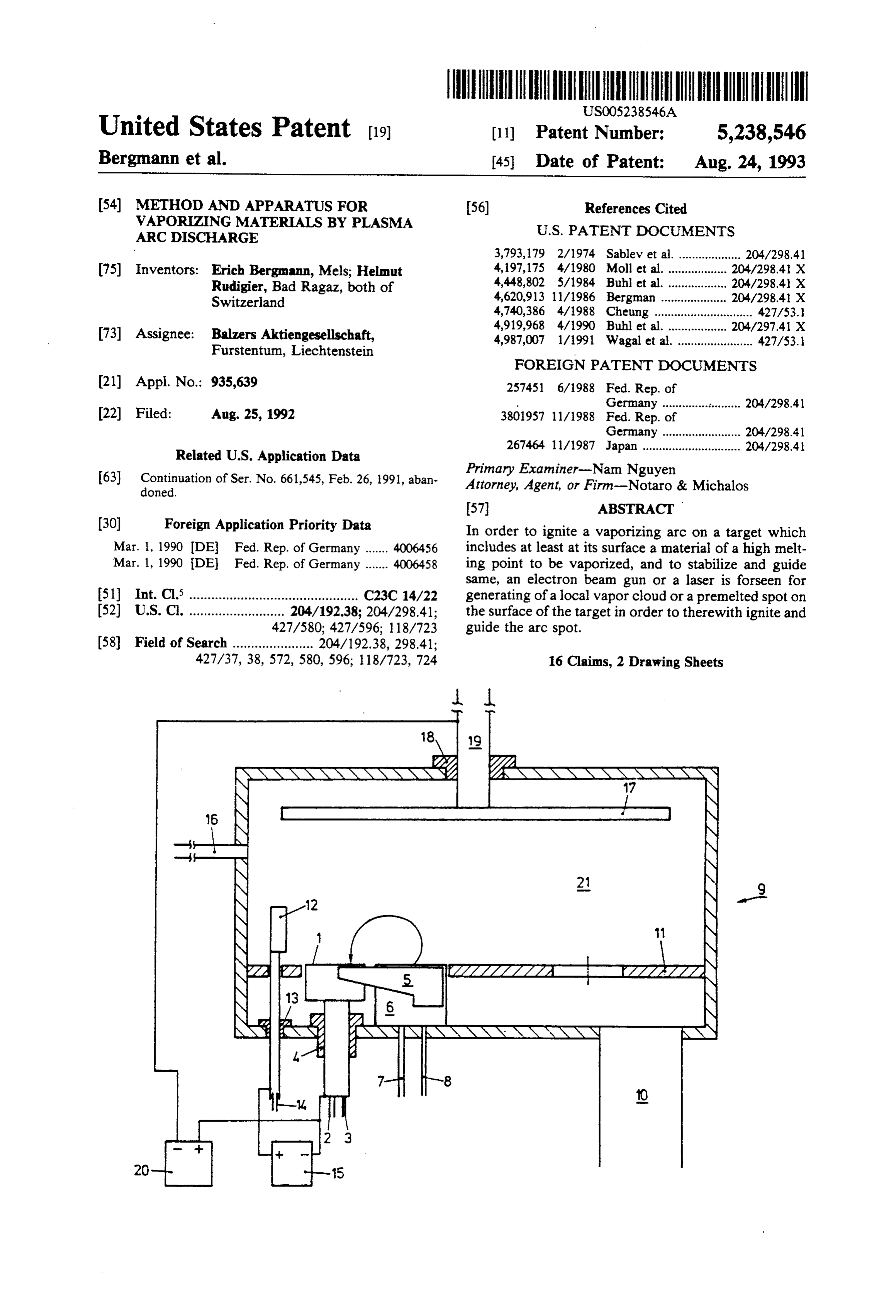
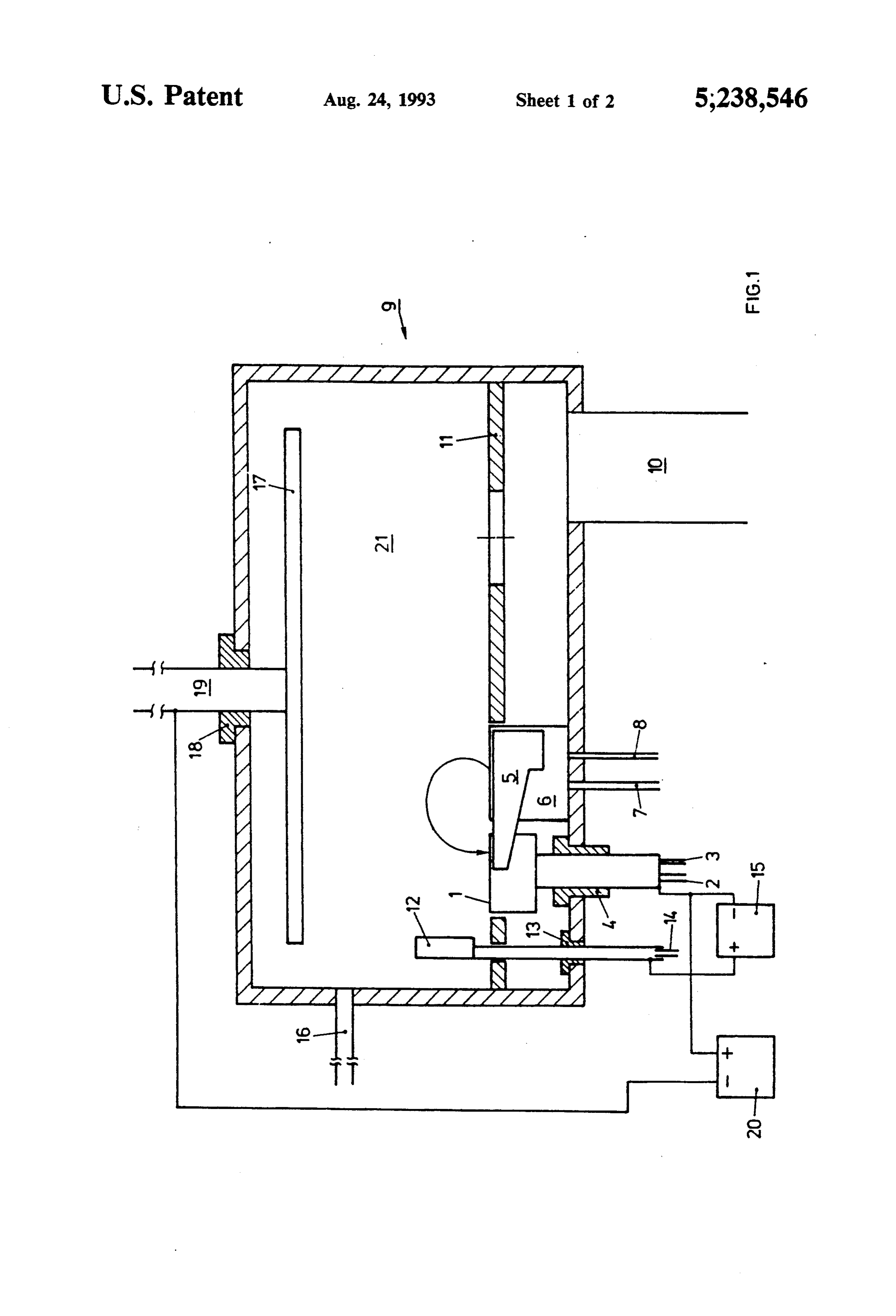
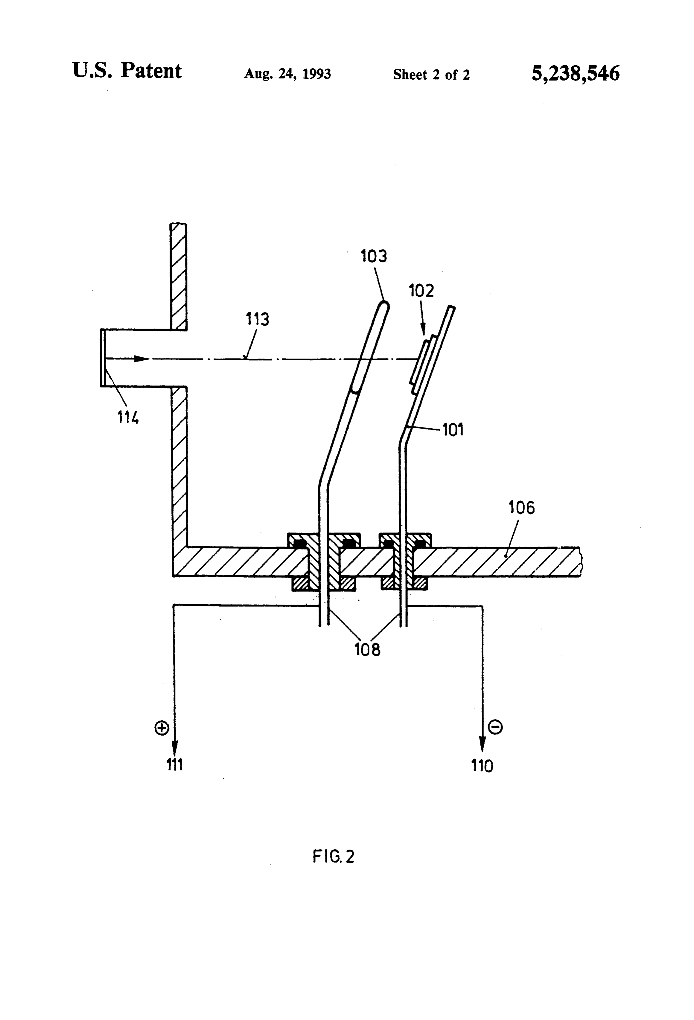
whereby the guiding of the electron beam or laser beam FIG. 1 is an illustration of a high vacuum apparatus can proceed obviously in accordance with a preset having a spark discharge arrangement and an electron pattern according to which a regular eroding of the 25 gun; and surface of the target by means of the guided arc or spark FIG. 2 illustrates a schematic of a principle arrange spot is guaranteed. ment of an inventive apparatus, suitable for practicing Still a further object is to provide a method operated examples 4 and 5 herein.
such that, taken at a mean time span, the operational output of the arc discharge exceeds the operational 30 DESCRIPTION OF A PREFERRED output of the electron beam or of the laser and the EMBODIMENT vaporizing of the material at the surface of the target A conventional electron gun 6 is mounted in a high occurs predominantly by means of the arc discharge. vacuum apparatus 9 having a corresponding pumping Yet a further object is to provide a method in which opening 10 for the evacuating of the vacuum apparatus the energy density of the electron beam or laser beam is 35 9 which gun 6 is cooled by a water cooling circuit 7, 8. controlled such that a discharge current of more than 30 The electron gun 6 is arranged such that an electron amperes at a discharge voltage of merely 10 to 15 volts beam emitted from the electron gun is guided by the is made possible. pole shoes of an electromagnet 5 to impact on the rotat A further object is to provide a method in which a ing target 1 mounted by means of an insulator 4 insu thinned atmosphere of an inert gas, oxygen, nitrogen, a lated against the bottom of the apparatus, which target gaseous carbon compound, a metal-organic gaseous or 1 is also cooled by a water cooling circuit 2, 3. boron containing compound is maintained in the vapor The target 1 acts simultaneously as cathode of the izing space located above the target. spark discharge. This spark discharge includes a water Yet a further object is to provide a method, in case cooled anode 12 having a water cooling circuit 14 and the surface of the target contains an easy melting mate 45 which is insulated against the apparatus by an insulator rial, in which the electron beam or laser beam is defo 13. In an exemplary embodied apparatus the anode 12 cussed to such an extent that the puddle around the foot has the dimensions of 30X 10 centimeters and is point of the arc of the arc discharge forms continuously mounted at a distance of about 10 centimeters from the a funnel whereby liquid target material flows repeatedly target 1.
in the bottom thereof, wherewith the arc is stabilized, A intermediate floor 11 acts as pressure stage for the without a guiding. case when reactive or inert gases are fed in via a gas Still a further object is to provide a method in which inlet 16 such that the pressure in the charging chamber the movement of the electron beam or laser focal point 21 does exceed the maximal allowable pressure for the occurs at such a high speed that the movement proper electron gun.
of the foot point of the arc discharge, which preferably 55 The circuit 15 symbolizes the power supply of the is a cathode foot point, is suppressed. spark whereby such can for instance be a high current Yet a further object is to provide an apparatus which generator. The articles to be coated, such as for instance is specifically suitable for an application in a plasma optical substrates, are mounted onto the rotating sub arrangement for depositing of coatings on a substrate. strate support 17 which is insulated by means of insula A further object is to provide a method of igniting the tors 18 against the apparatus. The passing through drive vaporizing arc at the target by means of an electron 19 for rotating support 14, is water cooled. The support beam or a laser in that a pre-melted spot is generated on for the substrate can be arranged to have a negative the surface of the target or a local vapor cloud is gener potential relative to the cathode by means of a voltage ated over a small area of the surface of the target, which source 20.
is sufficient for the igniting of a spark or the arc. 65 If now the high vacuum apparatus 9 is put into opera A further object is to provide a method in which the tion an electron beam is led onto the surface of the size of the spot of ignition is selected, where using an target 1 by means of the electron gun and the pole shoes electron beam of less than 10 square millimeters, to be of the electromagnet 5. By means of such a point like
Page 7
spot of the material to be vaporized, the material is through the center of the apparatus. Test specimens pre-melted on the surface on the target and this material were arranged on the mentioned disk. The charge of the is partly evaporated. By the impulse ionization of the vessel were 350g titanium and after charging the cruci evaporizing material with the electrons of the electron ble the apparatus was closed and pumped off. The speci beam, a partial ionization of the vapor is produced. This mens were heated by a method commonly known for ionization is sufficient for the ignition of the spark by a coatings of tools and their surfaces were cleaned in an switching of a no-load voltage between the two elec argon plasma. Thereafter, the electron beam gun was trodes of the spark, or between the target 1 and the switched anode 12. The jumping spark or arc, jumps, further watts. Theonvoltage and its output was increased up to 700 between the filament and the cruci more, onto the premelted, point-like spots on the sur 10 ble was 10.6 kV. The crucible was made to rotate a 2 face of the target. rpm. The focal spot with a diameter of about 1 millime The electron beam gun 6 is preferably arranged in such a way in the high vacuum apparatus 9 that the ter was focussed on the sector of the vessel located closer to the exit opening of the electron beam. The electron beam can be randomly guided on the surface of pressure inside of the chamber was less than 0.002 Pa. the target 1. By this movement, the arc can also be 15 Thereafter, arbitrarily guided on the surface of the target such that Its no-load the welding transformer was switched on. voltage was 41 Volts. A annular groove a more even and less sputtering evaporating of the ma terial of the target is possible. By interrupting the arca formed in the melt of which the bottom corresponded new spark is ignited automatically at the surface of the to the foot point of the electron beam. A very bright target by the point-like melting of the surface of the 20 plasma formed itself over this melt. target and accordingly the arc is sustained. By means of an additional supply apparatus the sub The depositing of a coating on the substrate which is strates were brought to a voltage of -80 V against the mounted on the substrate support 17 proceeds in accor potential of the crucible. The ion flow on the substrate dance with generally known techniques. support amounted to 8 amperes. Without the welding It is quite obviously possible to arrange a laser in the 25 transformer the substrate current was too low to be high vacuum apparatus instead of the electron gun 6 measured. After 15 minutes the current supply was shut wherewith now the surface of the target 1 is melted off and the apparatus flooded. A finely crystalline layer locally by a corresponding laser beam. Again, the ignit of 4 um titanium was present on the substrates. The ing of the spark occurs by the requisite ionization of the roughness of the surface of the test specimens remained vaporized material or, however, of the residual gas 30 unchanged and corresponded to a mean roughness atmosphere in the charging chamber 21. Also when depth of Ra, 0.04 um.
installing a laser in place of an electron beam gun it is EXAMPLE 2 possible to guide the corresponding spot on the surface of the target after the igniting of the arc by a guiding The same structure as in the example 1 was used. The thereof in order to secure a more even and less sputter 35 crucible was charged with 330g titanium. Thereafter, ing erosion of the surface of the target: initially the same procedure as in example 1 was fol The exemplary illustrated application of an electron lowed. The output of the electron beam gun was con beam gun in FIG. 1 is suitable for the igniting and guid trolled to 7.4 kW. The rotation of the crucible was not ing of a spark in any kind of vacuum apparatus. switched on. The electron beam was focussed to the EXEMPLARY EMBODIMENTS center of the vessel. The diameter of the focal point was
EXAMPLE 1
about 7 millimeters. The electron beam was wobbled by means of an automatic device with a frequency of 30
A cubic evaporating apparatus of the type BAI 640K Hertz. Thereafter argon, and specifically 40 standard was equipped as follows: A water-cooled crucible was cm3 per minute was led in. Thereafter, the welding mounted into the bottom of the apparatus in a decentral 45 transformer was switched on and its current was con ized manner. Adjacent the crucible an electron beam trolled up to 110 amperes. The voltage of operation was gun having an axial magnetic field was mounted in the 10 volts. A very bright plasma formed again over the botton of the apparatus. A cathode chamber of the melt, which plasma followed the wobble movement. apparatus was pumped off differentially and the dis Nitrogen was then fed, and specifically 420 standard tance between the exit of the electron bean and the 50 cm3 per minute.
center point of the cathode amounted to 100 millime . The substrates were subject to a DC-voltage of -20 ters. The electron beam gun had a maximal output of 8 volts. After one hour the power and gas supplies were kW. The crucible was made of copper, was water shut off and the apparatus was opened. 8 um stoichio cooled and had a diameter of 80 millimeters. It was metric golden coloured titanium-nitride was precipi electrically insulated with respect to the bottom of the 55 tated on the test disks. The hardness of the coating was chamber and also with respect to the ground of the gun. 2300 HV. It displayed an excellent resistance against It could be set into rotation by means of a motor. The erosion. The process temperature did not exceed 222 crucible was connected by a cable which was led, in an Celsius.
insulated means into the apparatus, to the negative pole EXAMPLE 3 of a DC supply apparatus of the kind used as a welding transformer (max. 250A) with copper cables of 10 milli A cubic vapor deposition apparatus of the type BAI meters. The positive pole of the supply apparatus was 640K was equipped a follows: A water-cooled crucible connected by a separate, electrically insulated and wa was mounted decentralized in its bottom. An electron ter-cooled throughput to a water cooled auxiliary an beam gun with an axial magnet field was mounted adja ode. This anode was rectangular, 250X 100 millimeters 65 cent the crucible in the bottom. The cathode space was and stood like a flag at a distance of 60 millimeters from pumped off differentially. The distance between the exit the crucible. A rotating disk was located opposite the of the electron beam and the center of the cathode bottom of the apparatus and had an axis extending amounted to 160 millimeters. The electron beam gun
Page 8
had a maximal output of 8 kW. The crucible was made material and having a focal length of 500 millimeters of copper, was water-cooled and had a diameter of 80 located in front of the rotating mirror. millimeters. It was insulated electrically against the After reaching 2*103 Pa the power supply appara bottom of the chamber and the ground of the gun. It tus was switched on and a voltage of 100 V established could be made to rotate by means of a motor. The vessel between the cathode and the anode. Thereafter, the was connected by a cable which extended in an insu spark was ignited by means of a laser pulse of a duration lated manner into the apparatus to the negative pole of of 6 milliseconds and an energy of 30.5 joules. Thereaf a DC supply apparatus of the kind used as a welding ter, the not guided spark ran at about 20 Volts and 90 transformer (max. 250A) with copper cables of 10 milli amps. It has been discovered, that the condition of igni meters. The positive pole of the supply apparatus was O tion (threshold energy of the laser pulse) depends connected by a separate, electrically insulated and strongly on the surface condition of the target (ability of water cooled throughput to a water cooled auxiliary reflection) and on the rotational speed of the laser beam. anode. This anode was rectangular, 250X 100 millime The time interval between pulses can be selected such ters and stood like a flag at a distance of 60 millimeters that the bottom discharge burns continuously. This from the vessel. Opposite the bottom, a calotte having 15 allows a guiding of the spark on the surface of the cath plates was placed. The vessel was charged with 60 g ode. Instead of the mirror, it is also possible to use other silicon and the apparatus was closed and pumped off. optical elements, such as concave mirrors or screens. Thereafter, oxygen was led into the chamber and its Instead of the Nd:YAG laser it is also possible to use gas flow was controlled such that the pressure in the appa or semiconductor lasers.
ratus did not exceed 0.09 Pa. Thereafter, the electron 20 beam gun was switched on and its output was increased EXAMPLE 5 up to 600 Watts. In a cubic apparatus BAI 760Ka water cooled, circu About at the same time the crucible was set into rotat lar cathode support (diameter 120 millimeters, thickness ing and the welding transformer was switched on. Its 10 millimeters) was mounted at a distance of 200 milli current was controlled to amount to 140 amperes. After 25 meters from the center of the apparatus, that the angle 30 minutes the power supply was shut off. At the open between the perpendicular line on the surface and the ing of the apparatus it was seen that a transparent sili axis of the apparatus so amounted to 70. A rectangular con-oxide coating had been deposited on the glass pan tin target which was soldered onto a copper plate hav els. ing a thickness of 5 millimeters was screwed onto this 30 cathode support 50 that a good electrical contact could
EXAMPLE 4
be established between the tin target and the cathode
Such as schematically illustrated in FIG. 2, a water support. At a distance of 35 millimeters from the cath cooled, circular cathode support 101 (diameter 120 ode an anode was mounted which extended in an insu millimeters, thickness 10 millimeters) was mounted in a lated manner through the bottom of the apparatus, was cubic apparatus BAI 760K at a distance of 200 millime 35 water cooled and of an annular (inner diameter 70 mm) ters from the center of the apparatus such, that the angle shape having a circular cross-section (diameter 12 milli between the perpendicular line onto the surface and the meters), which anode was arranged parallel to the cath axis of the plant amounted to 70'. A circular titanium ode.
target 102 (diameter 120 millimeters) having a thickness The cathode (and accordingly the tin target) was of 3 millimeters which was soldered onto a circular (60 grounded and connected to the negative pole of a weld mm diameter) copper block of a thickness of 12 millime ing transformer (max. 250 amps). The anode was con ters was screwed on such, that it was possible to estab nected to the positive pole of this power source. The lish a good electrical contact between the titanium tar laser beam of a pulsed Nd:YAG lasers (500 Watts) was get and the cathode support. A water cooled (at 108) led through a window (diameter 40 millimeters) which annular (inner diameter 70 millimeters) anode 103 hav 45 at both sides was coated by a anti-reflecting layer into ing a circular cross-section (diameter 12 millimeters) the apparatus and focussed through the anode onto the was mounted parallel to the cathode, whereby the dis surface of the cathode. The distance between the win tance between the cathode and the anode was 35 milli dow and the cathode amounted to 280 millimeters. The meters and the anode extended in an insulated manner focussing of the laser beam was made by a lense (focus 13 through the bottom 106 of the apparatus. The cath 50 500 millimeters) covered at both sides with a anti-reflec ode was grounded and connected to the negative pole tion layer. The movement of the focussed laser beam 110 of a welding transformer (max. 250 amps), the with an area of 50 millimeters diameter on the target anode 103 was connected to the positive pole 111 of this was accomplished in that the laser was mounted outside power source. The laser beam 113 of a pulsed Nd:YAG of the apparatus onto a massive table which could be laser (500W) was led through a window 114 (diameter 55 moved in two directions independent from each other. 40 millimeters) which at both sides was coated by a After reaching 2*10-3 Pa argon was fed into the antireflection layer into the apparatus and focussed vacuum chamber until a pressure of 210-1 Pa was through the anode onto the surface of the cathode. The reached. By switching on the power supply apparatus a distance between the window and the cathode was 280 voltage of 100 Volts was established between the cath millimeters. The laser beam was deflected by 90 out ode an the anode. The spark was ignited by means of a side of the apparatus by means of a rotating di-electric laser pulse of a duration of 6 milliseconds and an energy mirror 112 of which the surface formed an angle of 0.5 of 2 joules and ran on the tin target. with the axis of rotation 122. By means of this rotation Thereafter, the spark ran at about 20 volts and 90 it was possible to rotate the focal point, i.e. spot (diame amps. It was seen that the condition of ignition (thresh ter 0.7 millimeters) of the laser beam on the titanium 65 old energy of the laser pulse) depended strongly on the target. The speed of rotation could be adjusted between condition of the surface of the target (capability of re 0 and 6000 rpm. The focussing was made by means of a flection) and, evidentially, from the rotational speed of biconvex lens 116 coated at both sides by an antireflex the laser beam.
Page 9
EXAMPLE 6 the arc discharge, the beam being in addition to the arc discharge and the spot following the local melt
In a cubic apparatus BAI 760K a cathode support ing; and was mounted at a distance of 200 millimeters from the means for guiding the beam over the surface of the center of the apparatus, which cathode support was target in order to stabilize and guide movement of water cooled and had a circular shape (diameter 120 the spot as it follows the local melting and the millimeters, thickness 10 millimeters) and such that the vapor cloud.
angle between the perpendicular line onto the surface 2. The apparatus of claim 1, wherein said means for and the axis of the apparatus amounted to 70. A round creating a beam comprises a laser, the beam comprising tungsten target (diameter 30 millimeters) of a thickness 10 a laser beam, the means for guiding comprising an ob of 5 millimeters was clamped onto this cathode support ject lens through which the laser beam passes, and so that a good electrical contact between the tungsten means for displacing the object lens for moving the target and the cathode support was established. At a small spot formed by the laser beam on the material to distance of 35 millimeters from the cathode an anode, be vaporized, in a guided periodically moving manner which extended in an insulated manner through the 15 on the surface of the target.
bottom of the apparatus, was water cooled and of an 3. The apparatus of claim 1, wherein said means for annular (inner diameter 70 millimeters) shape with a creating a beam comprises a laser for creating a laser circular cross-section (diameter 12 millimeters), was beam, the means for guiding comprising a moveable mounted parallel to the cathode. mounted mirror for deflecting the laser beam onto the The cathode was grounded and connected to the 20 material to be vaporized at the small spot, for guiding negative pole of a welding transformer (max. 250 amps). and moving the small spot on the surface of the target. The anode was connected to the positive pole of this 4. The apparatus of claim 1, wherein the means for power supply source. The laser beam of a pulsed guiding comprises means for displacing the target to Nd:YAG laser (500 watts) was led through a window move in a periodic repeating manner so that the small (diameter 40 millimeters) which at both sides was 25 spot moves on the surface of the target. coated by an anti-reflection layer into the apparatus and 5. The apparatus of claim 1, wherein the means for focussed through the anode onto the surface of the creating a beam comprises a laser for creating a laser cathode. The distance between the window and the beam including lens means for focusing the laser beam cathode amounted to 280 millimeters. The focussing of onto the small spot, the lens means having a focal length the laser bean (diameter of the laser beam onto the 30 exceeding 40 millimeters.
target: 0.65 millimeters) proceeded by a biconvex lense 6. The apparatus of claim 5, wherein the laser com (focus 500 millimeters) mounted outside of the appara prises a pulsed laser for igniting the arc. tus and coated at both sides by a anti-reflection material, 7. A method of vaporizing material in a vacuum by which lens could be arbitrarily moved on the tungsten means of an arc at a target wired as a cathode, which target. The controlling of the movement was computer 35 target includes at least at a portion of its surface, a mate controlled. After reaching 2*10-3Pa the power supply rial to be vaporized, the method comprising: apparatus was switches on and a voltage of 100 Volts forming an arc discharge within an area where a established between the cathode and the anode. There substantial part of an arc current of the discharge after, the spark was ignited by means of a ladder shaped flows mostly through a small spot at the surface of impulse of a total duration of 5 milliseconds and an the target which is wired as a cathode, for defining energy of 7.5 joules. The spark was recorded by a stor a footprint;
age cathode beam oscilloscope. forming a local vapor cloud by means of a beam at the By means of a procedure similar to the one of exam surface of the target, wherein the footprint follow ple 4 and 5 the spark could be guided continuously. the cloud, the beam being created at a location While there have been shown and described present 45 spaced from the arc discharge; and preferred embodiments of the invention it shall be dis stabilizing the footprint of the arc, by guiding the tinctly understood that the invention is not limited to beam to control the vapor cloud to be over the same and can be variously embodied and practiced footprint.
within the scope of the following claims. 8. The method of claim 7, comprising the production We claim: 50 of a puddle below the vapor cloud on the surface of the 1. An apparatus for vaporizing material under vac target.
uum conditions by means of an arc, and with a target 9. The method of claim 8, wherein the surface of the which includes at least at a part of its surface, a material target consists a melting material and the beam is defo to be vaporized, comprising: cussed to such an extent that the puddle around the base means for wiring the target as cathode of an arc evap 55 point of the arc forms continuously a funnel into which orator of the cathode spot type wherein an arc further liquid target material flows continuously where discharge burns on the material to be vaporized at with the arc is stabilized without any guiding. a small defined spot on the material; 10. The method of claim 7, in which the bean is means for forming an arc discharge and for directing guided on the surface of the target.
the arc discharge onto an area of the material, and 11. The method of claim 7, in which at a mean time where a substantial part of an arc current from the span an output of the arc exceeds the output of the means for wiring flows mostly through the small beam.
spot on the material; 12. The method of claim 7, in which an energy den means for creating a beam directed toward the target sity of the beam is controlled such that a discharge for locally melting the material of the target and 65 current of more than 10 amperes at a discharge voltage thus producing a local vapor cloud on the surface of merely 10 to 15 volts is made possible. of the target near the spot, the means for creating 13. The method of claim 7, in which an atmosphere of the beam being spaced from the means for forming an inert gas, oxygen, nitrogen, a gaseous carbon com
Page 10
pound, a metal-organic gaseous compound or a com rial in a vapor depositing by plasma arc on to the sub pound containing boron is maintained in the vaporiza State.
tion space located above the target. 16. The method of claim 15 including providing an 14. The method of claim 7 wherein the beam com prises an electron beam or a laser beam having a focal atmosphere in the vacuum selected from the group point, and wherein the movement of the electron beam consisting of nitrogen, oxygen and a gaseous carbon or the laser beam focal point proceeds with such speed compound, so that the vaporized material reacts with that the movement proper of the footprint of the arc the atmosphere and condenses on the substrate in the discharge is suppressed. form of a coating selected from the group consisting of 15. The method of claim 11, including a substrate in 10 carbides, oxides and nitrites.
the vacuum and means for utilizing the vaporized mate k sk
Provenance
- Collection
- Cited prior art
- Original PDF
- patentimages.storage.googleapis.com →
- Filed
- 1992-08-25
- Pages
- 10
- Method
- pdftotext (the PDF's own text layer) + pdftoppm 300dpi page scans
- Source
- Google Patents bibliographic record
- Granted
- 1993-08-24
- Inventors
- Erich Bergmann; Helmut Rudigier; Balzers AG
- Transcribed from
- patentimages.storage.googleapis.com →