patent · US5152309
Valve control apparatus
6 October 1992
Page 1 — bibliographic record
United States Patent (19) 11 Patent Number: 5,152,309 Twerdochlib et al. (45) Date of Patent: Oct. 6, 1992 (54) VALVE CONTROL APPARATUS which is controlled by a computer 32 to open or close 75 Inventors: Michael Twerdochlib, Oviedo; David the valve in steps within a gas flow line 24 to deliver a E. Bateman, Geneva, both of Fla. desired rate of flow. A flowmeter 30 is provided along the gas flow line 24 for measuring the flow and input 73) Assignee: Westinghouse Electric Corp., ting this flow to the computer 32. The computer 32 Pittsburgh, Pa. calculates rate of flow information obtained from the 21 Appl. No.: 706,912 flowmeter 30 and controls the stepper motor 28 to open 22 Filed: May 29, 1991 or close the valve 22 as necessary in accordance with the received rate of flow information and a desired rate 51) Int. Cl. ............................................... G05D 7/06 of flow preprogrammed into the computer 32. As a 52 U.S. C. ........................................ 137/8; 137/480; result, a precise desired rate of flow can be obtained. 37/487.5 Also, position indicators 34 may be added to the valve 58) Field of Search ..................... 137/486, 487.5, 8, 2 22 to indicate when the valve 22 is completely open or 56) References Cited completely closed. The valve 22 may be provided with
a return spring 36 to automatically close the valve 22 in the event of a power loss. The computer 32 may be 3,776,249 12/1973 Wailes ............................. 137/486 X programmed to detect a significant increase in the rate 4,134,423 1/1979 Mayer ........... ... 137/487.5 X of gas flow being closing the valve 22 accordingly. 4,690,163 9/1987 Steinemann ..................... 37/486 X Additionally, a pressure switch 38 may be provided 4,813,443 3/1989 Pounder ........ ... 137/487.5 4,926,903 5/1990 Kawaii............................. 137/486X along the gas flow line 24 to cause the valve 22 to close upon a pressure change. Finally, temperature 40 and
Primary Examiner-Alan Cohan pressure 42 sensors may be added along the gas flow 57 ABSTRACT line so that the computer 32 can calculate and maintain The present invention provides a valve control appara a specific mass flow of gas. tus which can be programmed to deliver a desired flow of gas. A valve 22 is connected to a stepper motor 28 21 Claims, 4 Drawing Sheets
COMPUTER
DISPLAY
Page 2
Drawing sheet — no readable text.
Page 3
Drawing sheet — no readable text.
Page 4
Drawing sheet — no readable text.
Page 5
Drawing sheet — no readable text.
Page 6
Another object of the present invention is to provide
WALWE CONTROL APPARATUS a valve control apparatus whose operation can be veri fied.
BACKGROUND OF THE INVENTION A further object of the present invention is to provide 1. Field of the Invention a valve control apparatus that automatically prevents a The present invention is directed to a valve control gas flow in the event of a power loss. apparatus for controlling a gas control valve to deliver Another object of the present invention is to provide a precisely measured flow of gas, and more particularly, a valve control apparatus that automatically prevents a gas flow immediately upon detection of a sudden large to a valve control apparatus which controls a valve to 10 increase in gas flow.
precisely obtain a particular rate of gas flow or maintain A still further object of the present invention is to the flow within a particular range, by controlling the provide valve to open or close in accordance with a measured prevents aa control gas flow apparatus that quickly and briefly upon detection of excessive pres rate of flow to obtain a desired rate of gas flow. sure in the environment in which it operates. 2. Description of the Related Art 15 Finally, an object of the present invention is to pro It is often necessary to control or limit a flow of gas vide quickly and precisely. For example, a gas flow line can mass aflow valve control apparatus that provides a constant have a flowmeter for monitoring gas flow. The flowme perature. of gas independent of gas pressure and tem ter is a delicate and expensive device. If the gas flow in The present invention attains the above objects by the gas flow line exceeds a certain rate (or delivery), the 20 providing a valve control apparatus which can be pro flowmeter will be damaged or destroyed.
For example, in an Air Inleakage Monitor (AIM), connected to deliver grammed to
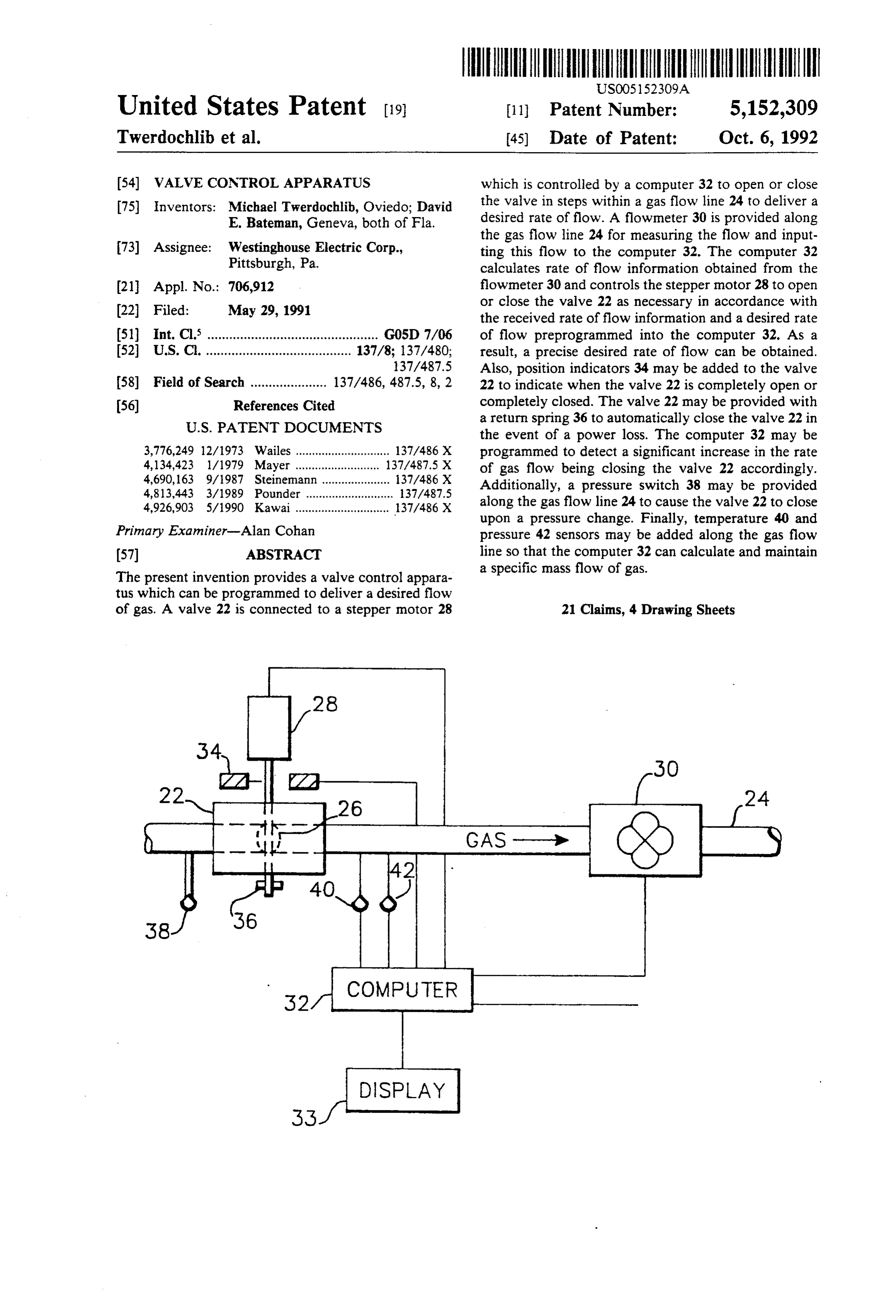
a desired flow of gas. A valve is stepper motor which is controlled by a produced by Westinghouse Electric Corp., a flowmeter computer to open or close the valve within a gas line to is used to measure the leakage of air into a steam tur deliver a desired rate of flow. A flowmeter is provided bine. As shown in FIG. 1, air is routed from the pipe 2 25 along the gas line to provide a rate of flow signal and through a flowmeter 4 via the by-pass 6 as long as the this signal is input to a control device such as a con flow is below 50 cfm. However, when air flow in the puter. The computer determines rate of flow from the by-pass reaches 50 cfm, a bladder 8 is deflated by a flowmeter input and controls the stepper motor to open valve control unit 10 so that the air flows through the pipe 2, thus significantly reducing air flow through the 30 or close the valve as necessary in accordance with the rate of flow and pursuant to a desired rate of flow pre by-pass 6. The by-pass 6 is connected to the flowmeter programmed into the computer. In this manner, a pre 4 at a pipe joint 11 and to an extension of pipe 2 at pipe cise desired rate of flow can be obtained. 12. During normal operation of the turbine, deflation of These together with other objects and advantages the bladder is sufficient to prevent air flow through the which will be subsequently apparent, reside in the de flowmeter from exceeding 50 cfm, so that damage to the 35 tails of construction and operation as more fully herein flowmeter is avoided and measurement of air flow by after described and claimed, reference being had to the the flowmeter can continue, although less accurately. accompanying drawings forming a part hereof, wherein However, there are certain circumstances in which net like numerals refer to like parts throughout. air flow through the air inleakage monitor is considera bly higher than in normal operation. For example, dur BRIEF DESCRIPTION OF THE DRAWINGS ing pump-down the net flow can reach and exceed 6000 FIG. 1 illustrates a prior art air inleakage monitor cfm. Under these circumstances, the air flow through without the computer controlled gas control valve pro the flowmeter can exceed 50 cfm even when the blad vided by the present invention; der is deflated. Thus, the bladder device offers no pro FIG. 2 is an illustration of the computer controlled tection against damage or destruction to the flowmeter. 45 gas control valve of the present invention; and SUMMARY OF THE INVENTION FIGS. 3A and 3B are a flowchart of the control pro cess performed by the computer to control the gas con
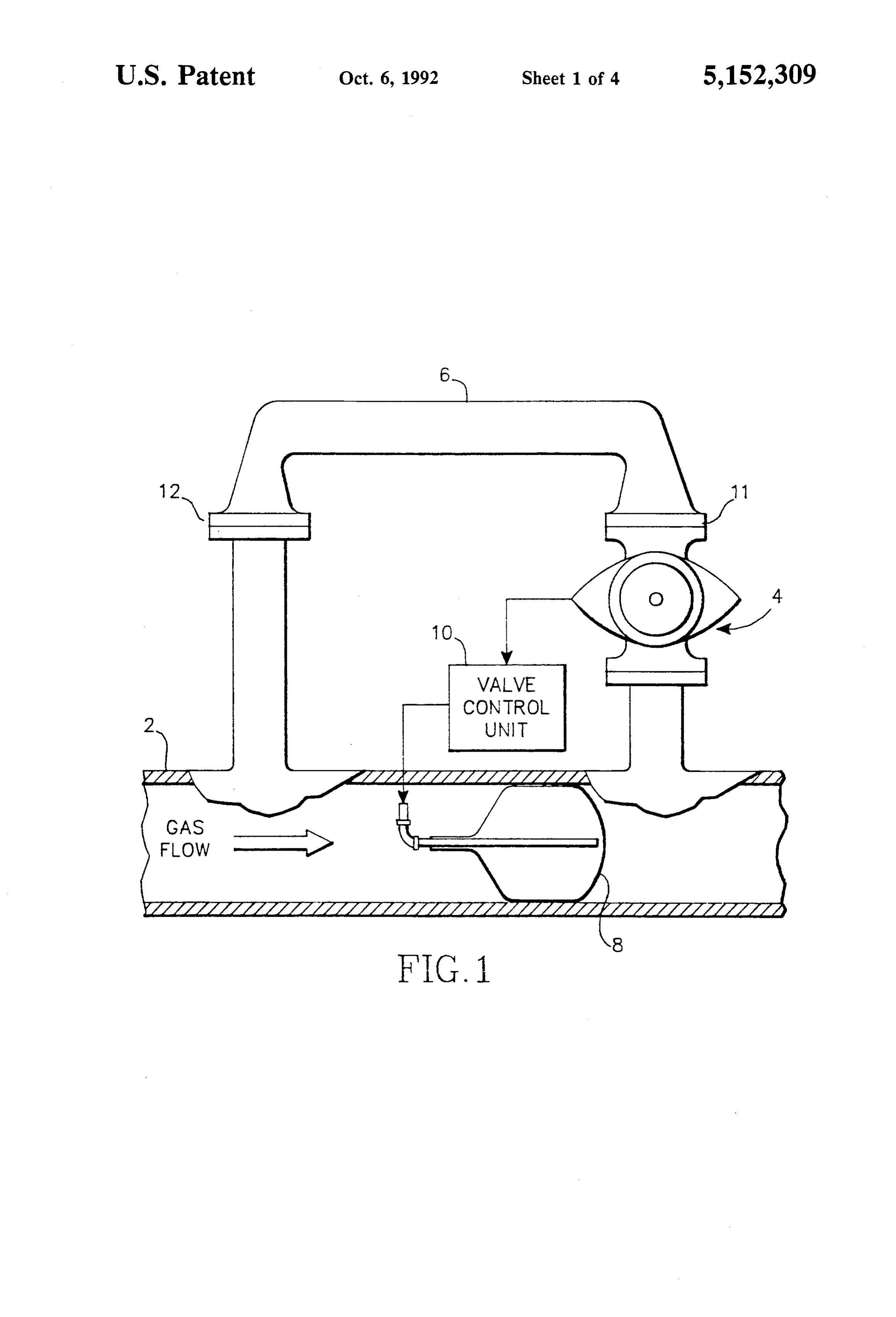
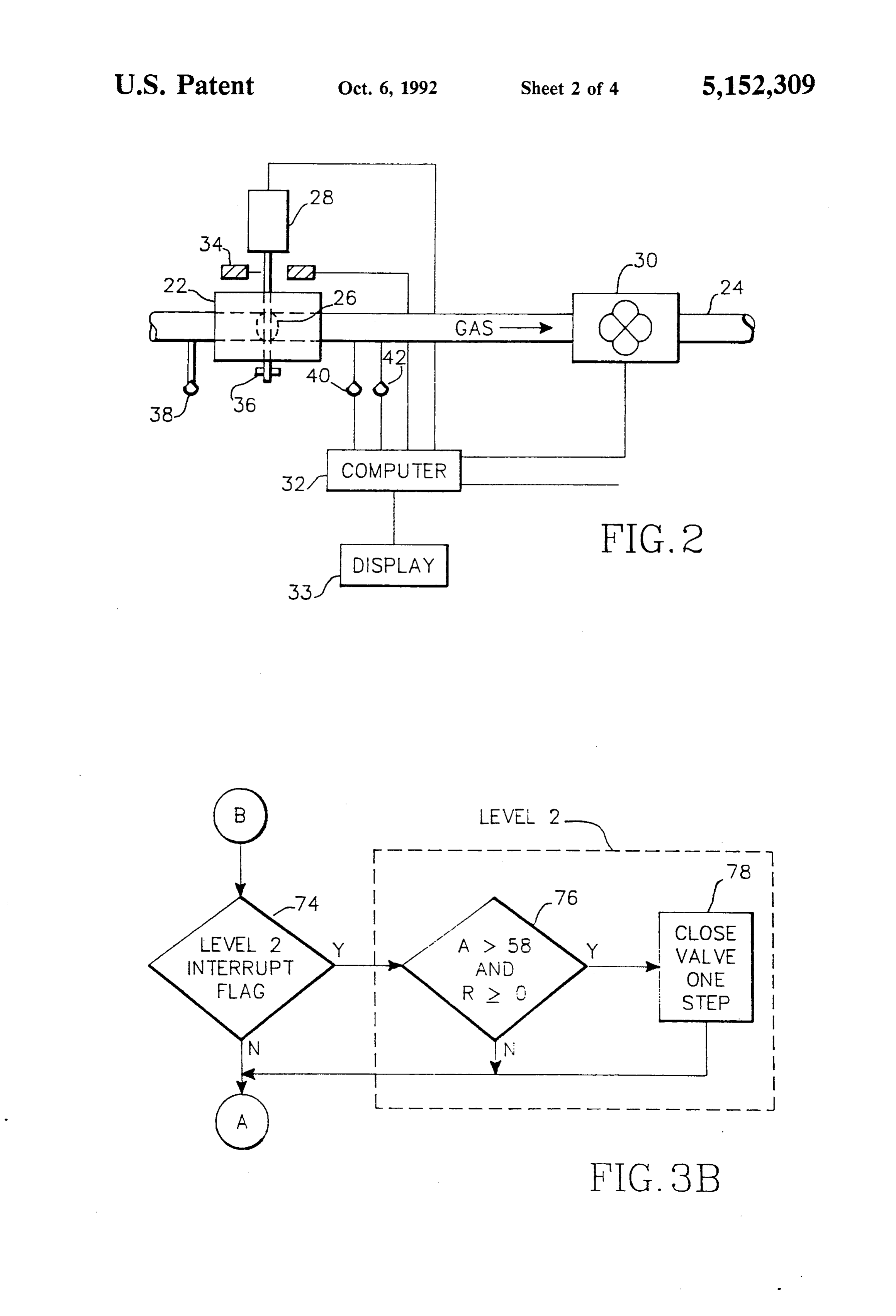
An object of the present invention is to provide con trol valve in the present invention;
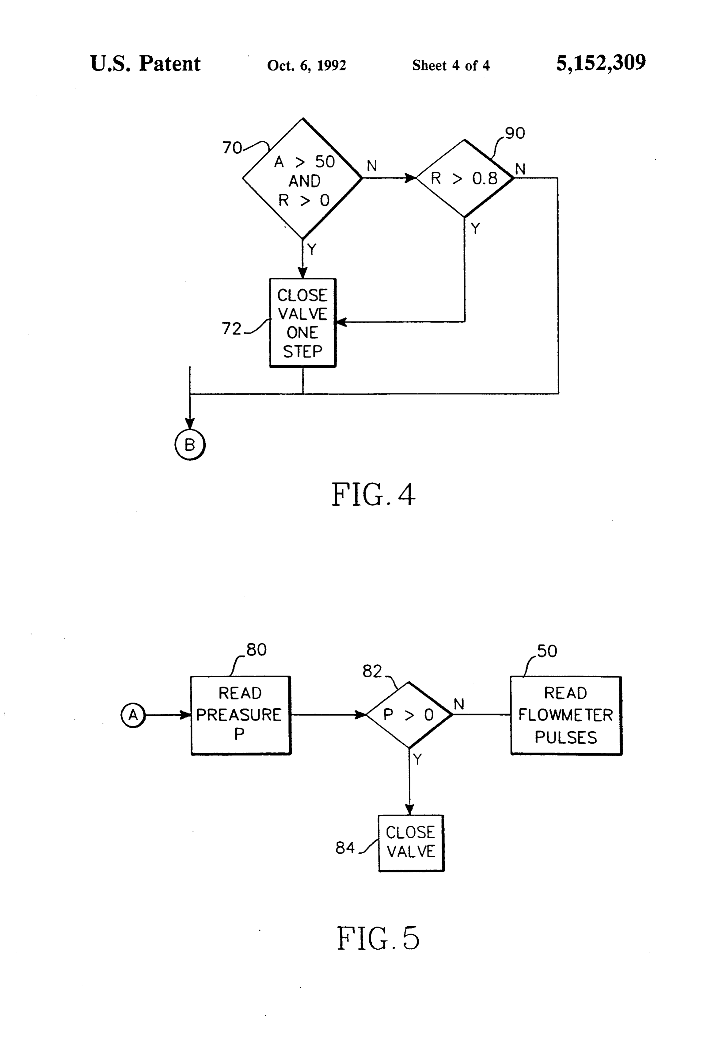
trol of a gas flow with a high degree of precision. FIG. 4 is a flowchart of the control performed in the Another object of the present invention is to provide 50 fourth embodiment of the present invention; control of the gas flow in accordance with a prepro FIG. 5 is a flowchart of the control performed in the grammed desired flow rate. fifth embodiment of the present invention. A further object of the present invention is to provide DESCRIPTION OF THE PREFERRED control of a gas flow in accordance with a measured EMBOOMENTS current flow rate. 55
Also, an object of the present invention is to prevent FIG. 2 is an illustration of the valve control apparatus a gas flow if the rate of flow reaches a certain amount. of the present invention. A conventional throttle plate Still another object of the present invention is to valve 22 is provided in a gas flow line 24 to control the reduce or prevent a gas flow if the rate of flow increases rate of gas flow therein. The plate valve is preferably very rapidly. inserted between the pipes at joint 12 and a correspond An object of the present invention is to prevent dam ing thickness spacer is provided in joint 11. However, age to equipment such as a flowmeter due to an exces other positions along pipe 6 are possible. The valve is sive rate of flow. manufactured by Westinghouse. The supplier to Wes A still further object of the present invention is to tinghouse is Electrical Design and Development, 7240 prevent damage to a flowmeter by controlling the 65 Old Cheney Hwy., Orlando, Fla. 32807. The throttle amount of gas that flows therethrough without sacrific plate valve 22 has a throttle plate 26 positioned within ing continuing operation of the flowmeter when possi the gas flow line 24. The throttle plate 26 is movable ble. within the gas flow line 24 by a conventional stepper
Page 7
motor 28 to allow a variable amount of gas to flow puter. If the position data provided by the position through the throttle plate valve 22. The stepper motor indicators 34 is not consistent with the instruction pro 28 adjusts the throttle plate 26 in small increments so as vided to the throttle plate valve 22, the computer deter to provide a precise opening that may fall anywhere mines that a malfunction has occurred and display an within a wide range from all the way open to all the indication of the malfunction of the display 33. way closed. In a third embodiment of the present invention, the A flowmeter 30, like the flowmeter 4 of the prior art, throttle plate valve is provided with a return spring 36 is also provided in the gas flow line 24 at a position which causes the throttle plate valve 22 to automati downstream from the throttle plate valve 22. The flow cally close in the event of a power loss. The return meter 30 indicates a rate of gas flow along the gas flow 10 spring 36 should be strong enough to close the throttle line 24 by outputting to a computer 32 tach pulses repre plate 26, but weak enough so as not to overpower the senting rotations of the flowmeter 30. A suitable com stepper motor. A spring meeting these requirements can puter 32 is a SC87C451CCA68 available from SYG be made by Servo Meter Corp. The spring is 25 ounce NETICS. inches when closed and 30 ounce inches when open. The computer 32 calculates the gas flow from the 15 In a fourth embodiment of the present invention, the tach pulses and displays the flow on a display 33 and computer 32 detects an increase in the rate of gas flow calculates a rate of change in the gas flow by comparing through the flowmeter 30 when the rate of tach pulses averages of the most recently calculated gas flows. The increases, and operates the stepper motor to begin clos computer 32 is also connected to the stepper motor 28. ing the throttle plate valve 22 when the rate of increase The computer 32 controls operation of the stepper 20 of the gas flow is significant (i.e. 0.8 cfm per tach pulse), motor 28 in accordance with a desired rate of gas flow so as to anticipate a sudden large flow increase. Specifi preprogrammed in the computer 32, in accordance with cally, since the computer 32 continually calculates the a current gas flow, and in accordance with the rate of gas flow, gas flows determined by the computer 32 over change of the gas flow. This process will be discussed in a period of time are averaged and compared to a previ more detail with respect to FIGS. 3A and 3B. 25 ous average to calculate a rate of change in the gas flow. For example, in a first embodiment of the present If the rate of change is an increase which exceeds a invention, the computer 32 is programmed to maintain preprogrammed amount, the computer operates the the rate of gas flow at just less than a specified amount stepper motor to begin to close the throttle plate valve. preprogrammed in the computer. When the computer The computer can be similarly programmed to respond 32 determines that the gas flow exceeds the specified 30 to a sudden decrease in flow.
amount and the flow rate is increasing, it operates the In a fifth embodiment of the present invention, a stepper motor 28 to close the throttle plate 26 by a step. pressure switch 38 is provided along the gas flow line 24 If, on the other hand, the computer 32 determines that and connected to the computer. When an excessive gas the gas flow is under the specified amount and the rate flow occurs along the gas flow line 24, the excessive of low is not increasing, it operates the stepper motor to 35 flow is detected by the pressure switch 38 and indicated open the throttle plate 26 by a step. The computer 32 to the computer. In response, the computer rapidly constantly reads the tach pulses from the flowmeter 30 and calculates the gas flow upon every tach pulse so closes the throttle plate valve 22 so as to prevent a gas that precise and rapid control of the throttle plate valve ment providedthealong flow through flowmeter 30 or other sensitive equip the gas flow line 24 that might 22 can be obtained. This process will be described in damage the flowmeter 20 or the sensitive equipment. detail in FIGS. 3A and 3B and the related discussion Control and analysis of the gas flow is then continued thereto.
As discussed, the prior art Air Inleakage Monitor closed. with the throttle plate valve 22 completely starting shown in FIG. 1 is incapable of preventing damage to In a sixth embodiment of the present invention, a the flowmeter 4 when net air flow through the air in 45 temperature leakage monitor is so excessive that airflow through the vided along sensor the 40 and pressure sensor 42 are pro gas flow line and connected to the by-pass exceeds 50 cfm even when the bladder is de computer 32. The computer 32 reads temperature data flated or when an air surge occurs. However, by pro and pressure data from these sensors and uses this data viding the computer controlled gas control valve 22 at to compute a desired mass flow of the gas that is inde joint 12 along the by-pass 6 in FIG. 1, air flow through SO pendent of the gas pressure and temperature. Specifi the by-pass 6 can be precisely controlled, so that the cally, the flow rate v (liters/sec), as calculated by the valve 22 limits air flow to the flowmeter 4 when the computer calculates that the gas flow approaches 50 computer as explained above, is multiplied by Pressure (in atmosphere)\temperature (in cfm. As a result, damage to the flowmeter 4 is avoided Kelvin)x1\R and, when air flow through the flowmeter 4 is not great 55 enough to damage the flowmeter 4, the operation of the where R is the ideal gas constant R=0082 liter atmos flowmeter 4 can be continued as efficiently as possible. pheres mole Kelvin.
In a second embodiment of the present invention, the FIG. 3 is a flowchart of the control process per throttle plate valve 22 is provided with position indica formed by the computer to control the gas control tors 34. The computer reads position data from the valve in the present invention. It is preferred that this position indicators 34 to determine if the throttle plate process be implemented in a language such as Cand 851 26 is completely open or completely closed within the product line assembly language. The computer reads 50 gas flow line 24. The computer uses this information to tachometer type (tach) pulses output by the flowmeter verify operation of the throttle plate valve 22. For ex and determines 52 whether a level 1 interrupt flag has ample, if the computer has instructed the throttle plate 65 been set indicating that the process denoted level 1 in valve 22 to maintain the throttle plate 26 to be com FIG. 3 is to be executed. The level 1 interrupt flag is set pletely open within the gas flow line 24, the position if a tach pulse is received from the flowmeter or if 4.0 indicators 34 should indicate this position to the com seconds elapses. If the level 1 interrupt flag has been set,
Page 8
the computer reads 54 a count that has accumulated control valve is controlled in real time and the gas flow between the tach pulses. If the count is determined 56 to is controlled quickly and accurately. exceed a maximum count, such as 44, 444, 460, which FIG. 4 is a flowchart of the control performed by the indicates that so much time has passed that the flowme computer 32 in the fourth embodiment. As discussed, in ter is not turning, the flow is set 58 to a minimum flow the fourth embodiment, the computer 32 begins closing amount, such as O. cfm. If, however, the count does not the stepper motor when the gas flow rate increases exceed the maximum count, then the computer calcu significantly. In FIG. 4, step 90 is provided in addition lates 60 the flow with an inverse function of the count, to the control shown in FIG. 3. The computer deter such as in the formula: mines 90 whether the rate of change exceeds 0.8 cfm per O tach pulse. If so, the computer closes the valve by one step by transmitting a signal to the valve.
4444444 FIG. 5 is a flowchart of the control performed in the FLOW (iii)x O fifth embodiment. As discussed in the fifth embodiment, the computer responds to an excessive gas flow de
Next, the computer 32 calculates 62 an average flow 15 tected by the pressure switch 38 by rapidly closing the (A) by averaging the most recently determined flows. signal PInfrom valve. FIG. 4, the computer reads 80 a pressure the pressure switch 38. If the pressure
For example, an average is computed for the last three exceeds a threshold flows. The computer 32 calculates 64 a conventional changes, for example,amount, from 0 then the pressure signal to 1. The computer deter rate of change (R) of the flow using the most recently mines 82 whether the pressure signal indicates an exces calculated average flows. For example, if the flow is sive pressure. If so, the computer closes 84 the valve by below 10 cfm, the most recently computed average is transmitting a signal to the value, and control proceeds used to calculate the rate of change. If the flow is be to step 50, as in FIG. 3.
tween 10 and 20 cfm, an average of the last three aver The many features and advantages of the invention ages is used. If the flow is greater than 20 cfm, the last 25 are apparent from the detailed specification and thus it four averages are used. If the computer determines 66 is intended by the appended claims to cover all such both that the average flow is less than 50 CFM and that features and advantages of the invention which fall the rate of change of the flow is not increasing, then the within the true spirit and scope of the invention. Fur computer 32 opens 68 the valve by one step by transmit ther, since numerous modifications and changes will ting a signal to the valve. If the computer 32 determines 30 readily occur to those skilled in the art, it is not desired 70 that the average flow is greater than 50 CFM or that to limit the invention to the exact construction and the rate of change of flow is increasing, then the com operation illustrated and described, and accordingly all puter 32 closes 72 the valve by one step by transmitting suitable modifications and equivalents may be resorted a signal to the valve. Otherwise, the valve remains in its to, falling within the scope of the invention. current position. 35 What is claimed is:
By executing the level 1 process for every tach pulse 1. A valve control apparatus for precisely controlling received from the flowmeter, the computer maintains a fluid flow in a fluid flow line, comprising: precise and immediate control of the gas control valve. measuring means provided in the fluid flow line, and A rapid change in the amount of gas flow is thereby for producing a flow signal corresponding to the responded to quickly. fluid flow, a temperature signal corresponding to The computer 32 executes a level 2 process, as illus fluid temperature and a pressure signal correspond trated in FIG.3B, every 0.1 seconds to provide a highly ing to fluid pressure;
accurate control of the gas flow without overcontroll a valve provided inside the fluid flow line; and con ing the valve. As a result, if 0.1 seconds has elapsed 45 trol means for controlling said valve to vary flow since the last execution of the level 2 process, at the end in the gas flow line responsive to the flow signal, of the level 1 process the level 2 process is executed. the temperature signal and the pressure signal.
Thus, the computer 32 determines 74 whether a level 2 wherein A valve control apparatus according to claim 1, interrupt flag is set indicating that 0.1 seconds has sive to a said rate control means controls said valve respon of change of the flow.
elapsed. If so, the computer determines 76 whether the 3. A valve control apparatus according to claim 1, average flow exceeds 58 CFM and the rate of change of further comprising position indicators operatively con flow is not decreasing. If both these conditions are met, nected to said valve and indicating when said valve is the computer closes 78 the valve by one step by trans fully open and fully closed to said control means. mitting a signal to the valve. A fine control is thus main tained of the gas control valve by using a position 55. further valve 4. A control apparatus according to claim 1, comprising a return spring operatively con change every 0.1 seconds if necessary. As a result, the nected to said valve and closing said valve during a computer controlled gas control valve is preferably power loss.
utilized in an air inleakage monitor to prevent or limit 5. A valve control apparatus according to claim 1, gas flow through the flowmeter only when the flow further comprising a pressure switch provided within becomes so excessive that the flowmeter could be dam the fluid flow line, and said control means closes said aged. At all other times, the gas flow is allowed to valve when said pressure switch detects a pressure ex proceed and the flowmeter 4 can be utilized to measure ceeding a predetermined pressure.
the gas flow. 6. A valve control apparatus according to claim 1, The process described in FIGS. 3 and 4 is performed further comprising a temperature sensor and a pressure in a continual loop within the computer so that the 65 sensor, provided within the fluid flow line and produc computer continually checks the level 1 and level 2 ing the temperature and pressure signal, and interrupt flags to determine whether the level 1 and said control means calculates a constant mass flow of level 2 processes should be executed. Thus, the gas fluid based on the temperature and pressure and
Page 9
flow signals, and said control means controls said flow line by moving the valve responsive to the rate of valve to obtain the constant mass flow of fluid. change of the measures.
7. A valve control apparatus according to claim 2, 14. A method according to claim 12, wherein step (a) wherein said control means moves said valve to narrow includes reading tach pulses from a flowmeter and cal the opening when the flow exceeds a predetermined culating the fluid flow based on a time between the tach flow and when the rate of change of flow exceeds a pulses.
predetermined rate of change. 15. A method according to claim 12, further compris 8. A valve control apparatus according to claim 2, ing step (f) closing the valve when the rate of change of wherein said control means moves said valve to the fluid flow exceeds a predetermined rate of change. broaden the opening when the flow does not exceed a O 16. A method according to claim 13, wherein step (e) predetermined flow and when the rate of change does includes moving the valve to narrow the opening when not exceed a predetermined rate of change. the fluid flow exceeds a predetermined flow and when 9. A valve control apparatus according to claim 2, the rate of change of the fluid flow exceeds a predeter wherein: mined rate of change.
said flow measuring means comprises a flowmeter, 15 17. A method according to claim 13, wherein step (e) and the flow signal comprises tach pulses corre includes moving the valve to broaden the opening when sponding to rotations of the flowmeter caused by the fluid flow does not exceed a predetermined flow the fluid flow, and and when the rate of change of the fluid flow does not said control means controls said valve when said exceed a predetermined rate of change. flowmeter produces one of the tach pulses. 20 18. A method according to claim 14, further compris 10. A valve control apparatus according to claim 2, ing step (c), repeating steps (a) and (e) every time the wherein said control means controls said valve when a flowmeter produces one of the tach pulses. predetermined time has elapsed, 19. A method according to claim 14 further compris 11. A valve control apparatus for precisely control ing step (c) repeating steps (a) and (e) every time a ling a fluid flow in a fluid flow line, comprising: 25 predetermined time elapses. a flowmeter, disposed in the fluid flow line, and nea 20. A method for precisely controlling fluid flow in a suring a fluid flow in the fluid flow line by output fluid flow line, comprising the steps of: ting tach pulses corresponding to rotations of said (a) reading pulses from a flowmeter indicating an flowmeter caused by the fluid flow; amount of the fluid flow in the fluid flow line; a throttle plate valve, disposed along the fluid flow 30 (b) performing steps (c) through (h) when one of the line and having a throttle plate movable inside the pulses is read and every predetermined time period; fluid flow line to create an opening in the fluid flow (c) obtaining a time count between times when each line; of the pulses is read;
a stepper motor, operatively connected to said throt (d) calculating a flow based on an inverse function of tle plate valve, and moving the plate in said throttle 35 the count when the count exceeds a maximum plate valve a step at a time to change the opening; count, and setting the flow equal to a minimum a temperature sensor, disposed along the fluid flow flow when the count exceeds the maximum count; line and measuring a temperature in the fluid flow (e) calculating an average flow based on the flow and line; previous flows;
a pressure sensor, disposed along the fluid flow line (f) calculating a rate of change of flow based on the and measuring a pressure in the fluid flow line; and average flow;
a computer, operatively connected to said flow me (g) opening a valve in the fluid flow line by a step ter, said temperature sensor, said pressure sensor when the average flow is less than a predetermined and said stepper motor, and controlling said step flow and when the rate of change of flow is de per motor to open and close the throttle plate in 45 creasing or equal;
said throttle plate valve responsive to the tempera (h) closing the valve by a step when the average flow ture, the pressure and the tach pulses received from exceeds a predetermined flow and when the rate of said flowmeter. change of flow is increasing; 12. A method for precisely controlling a fluid flow in (i) performing step (j) every predetermined time per a fluid flow line, comprising the steps of: 50 riod;
(a) measuring the fluid flow in the fluid flow line; () closing the valve when the average flow exceeds a (c) measuring a temperature of the fluid in flow line; second predetermined flow and when the rate of (d) measuring a pressure of the fluid in the flow line; change of flow is not decreasing; and and (k) repeating steps (a) through (j). (e) varying an opening in the fluid flow line by mov 55 21. A method according to claim 20, further compris ing a valve responsive to the fluid flow, tempera ing the steps of:
ture and pressure measures. (1) obtaining a pressure within the fluid flow line; and 13. A method according to claim 12, wherein step (a) (m) closing the valve when the pressure exceeds a includes calculating a rate of change of the fluid flow, predetermined amount.
and step (e) includes varying the opening in the fluid 60
Provenance
- Collection
- Cited prior art
- Original PDF
- patentimages.storage.googleapis.com →
- Filed
- 1991-05-29
- Pages
- 9
- Method
- pdftotext (the PDF's own text layer) + pdftoppm 300dpi page scans
- Source
- Google Patents bibliographic record
- Granted
- 1992-10-06
- Inventors
- Michael Twerdochlib; David E. Bateman; Westinghouse Electric Corp
- Transcribed from
- patentimages.storage.googleapis.com →