patent · US4790749
Kiln for firing ceramic materials such as tiles and the like
13 December 1988
Page 1 — bibliographic record
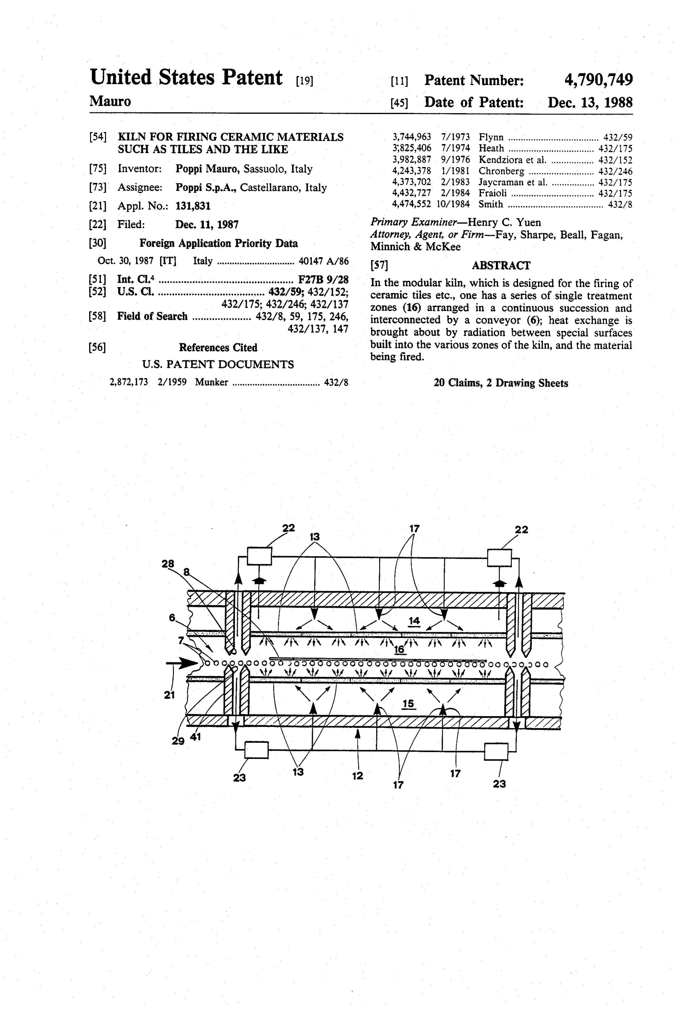
United States Patent (19) 11 Patent Number: 4,790,749 Mauro (45) Date of Patent: Dec. 13, 1988 54 KILN FOR FIRING CERAMIC MATERIALS 3,744,963 7/1973 Flynn .................................... 432/59 SUCH ASTILES AND THE LIKE 3,825,406 7/1974 Heath .................................. 432/175 3,982,887 9/1976 Kendziora et al................., 432/152 75) Inventor: Poppi Mauro, Sassuolo, Italy 4,243,378 1/1981 Chronberg .......................... 432/246 73) Assignee: Poppi S.p.A., Castellarano, Italy 4,373,702 2/1983 Jaycraman et al. ................. 432/175 4,432,727 2/1984 Fraioli................................. 432/175 (21) Appl. No.: 131,831 4,474,552 10/1984 Smith ..... - -- - ---- ---- -- -- -- --- --- 432/8
(22 Filed: Dec. 11, 1987 Primary Examiner-Henry C. Yuen
Attorney, Agent, or Firm-Fay, Sharpe, Beall, Fagan, (30) Foreign Application Priority Data Minnich & McKee
Oct. 30, 1987 (IT) Italy ............................... 40147 A/86 (57) ABSTRACT 51) Int. Cl." ................................................ F27B9/28 In the modular kiln, which is designed for the firing of 52 U.S. C. ...................................... 432/59; 432/152; ceramic tiles etc., one has a series of single treatment 432/175; 432/246; 432/137 zones (16) arranged in a continuous succession and 58 Field of Search ..................... 432/8, 59, 175, 246, interconnected by a conveyor (6); heat exchange is 432/137, 147 brought about by radiation between special surfaces (56) References Cited built into the various zones of the kiln, and the material
being fired.
2,872,173 2/1959 Munker .................................. 432/8 20 Claims, 2 Drawing Sheets
AATT.
: I -N 1N, -1N %
Page 2
Drawing sheet — no readable text.
Page 3
Drawing sheet — no readable text.
Page 4
KLN FOR FRING CERAMIC MATERIALSSUCH BRIEF DESCRIPTION OF THE DRAWINGS ASTILES AND THE LIKE The invention will now be described in detail, by way of example, with the aid of the accompanying drawings,
BACKGROUND OF THE INVENTION 5 in which:
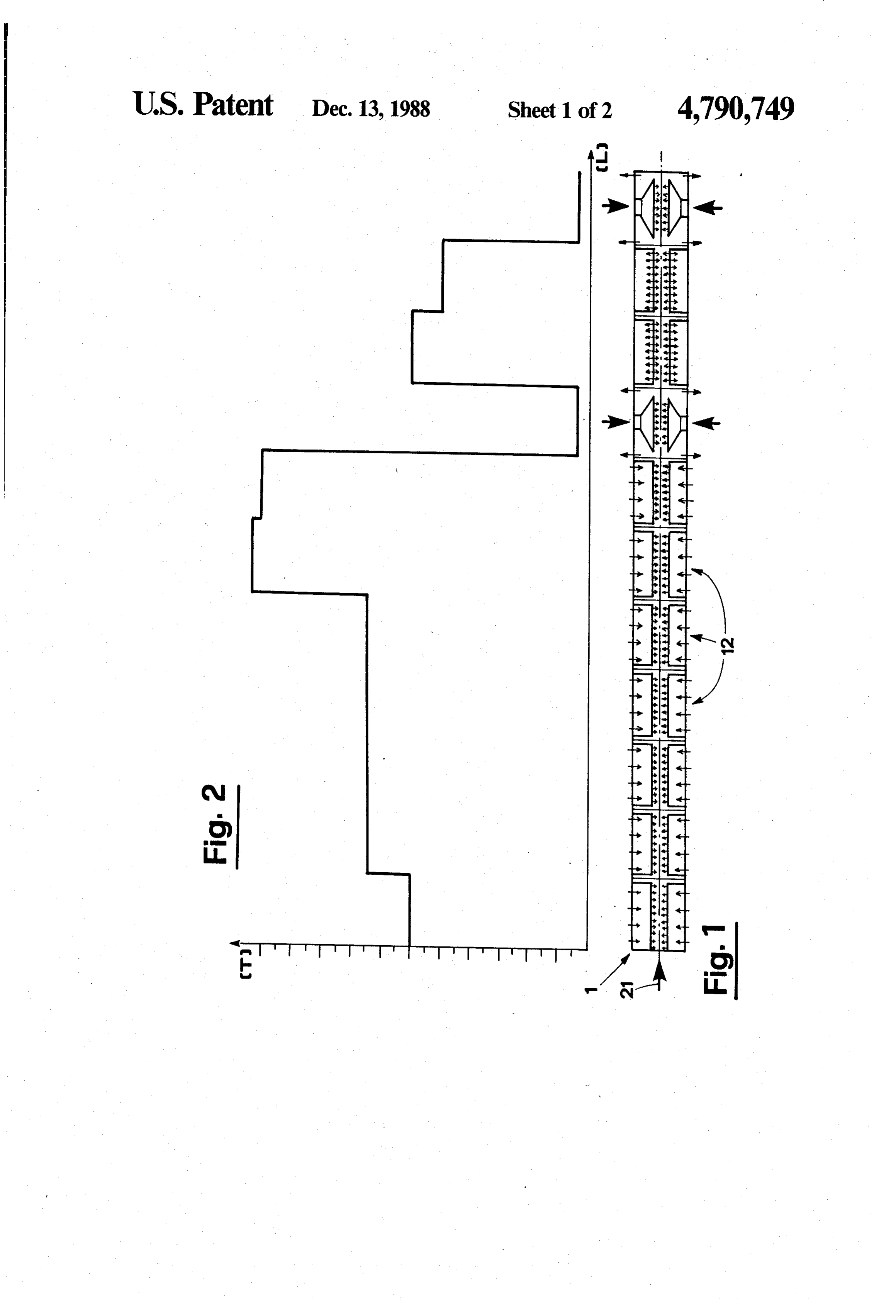
The invention relates to a kiln in which to fire ce FIG. 1 is the schematic representation of a kiln ac ramic materials such as tiles and the like. cording to the invention, viewed in longitudinal section Such a kiln is intended specifically, though not exclu through FIG. 2 a vertical plane;
shows an example of the firing curve obtained sively, for use in high speed firing processes effected on 10 with the kiln of FIG. 1;
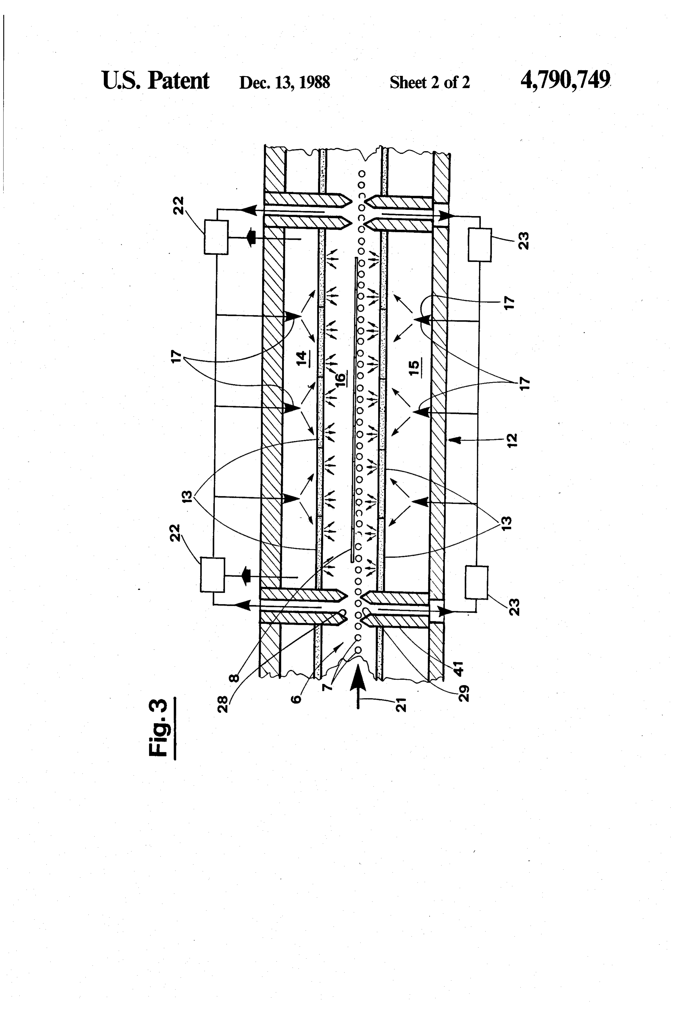
ceramic materials, and on ceramic tiles in particular. FIG. 3 illustrates a detail of the kiln, viewed in en Conventional high speed firing cycles are implemented larged scale.
using continuous roller kilns, in which material is fired while running through from end to end; more exactly, DESCRIPTION OF THE PREFERRED with the kiln operating at regular tempo, a precise dis 15 EMBODIMENT tribution of temperature is achieved along the longitudi With reference to the drawings, 1 denotes a kiln (con nal axis, from entry to exit. sidered in its entirety) suitable for firing ceramic tiles 8 This temperature appears as a continuous curve ex at high speed; the kiln comprises a series of sections, or hibiting an initial rise, an intermediate stretch, and a fall. treatment zones, arranged in succession and connected Passing through the kiln, the material is subjected to a 20 one to the next by way of a conveyor system consisting steadily increasing temperature while in the pre-heat in a table 6 made up of a plurality of power driven zone, then to maximum firing temperature, and thereaf rollers 7 disposed side by side with axes parallel in such ter, to a relatively gradual cooling; in practical terms, a way as to form a continuous bed. Each such zone the ceramic material is conveyed along the length of the features a precise temperature level that will be ob kiln from entry to exit through a succession of zones, 25 served in the graph of FIG. 2, in the case of the example being invested with thermal energy in some, and di illustrated; 'L' on the x axis, indicates the length of the vested of thermal energy in others. The method most kiln, and 'T', on the y axis, the temperature level. widely adopted in bringing about such exchanges of The single zones are thus identifiable from the rela heat in roller kilns is one based on convection, charac 30 tive temperature levels, and it will be seen in FIG. 1 that terized by the creation of two continuous and colliding each 12, such zone consists in at least one module, denoted illustrated in detail in FIG. 3. 21 denotes the direc flow paths: on the one hand, the ceramic material being tion in which the fired, which is carried forward into the firing zone by hence through thetiles 8 are conveyed through the kiln, single treatment zone, or module 12.
the rollers, and on the other, hot gases which pass from Tiles 8 sitting on the rollers 7 internally of the module the firing zone out into the flue. 35 12 are in receipt of thermal energy radiated from sur To obtain a given firing curve, different levels of faces located at given relative distances above and thermal energy are applied in order to produce a break below the table 6. The radiating surfaces are embodied in the effects of the collision for a given space and hold as panels 13 suspended side by side in a continuous one section of the kiln at constant temperature (the succession, which feature high thermal conductivity section in which the chemical and physical reactions and a high heat radiation coefficient, even at low tem relative to the firing process proper are allowed to take peratures.
place). The panels 13 are heated by burners 17, the hot gases This basic system of applying heat is beset by draw from which are played onto their reverse sides (the side backs deriving from the fact that, in passing through the opposite from that offered to the rollers, in each case) kiln, the material encounters convection currents of 45 internally of chambers 14 and 15 that are sealed off from dissimilar temperature, direction and rate of flow, and the chamber 16 occupied by the roller table and tiles, contact with the gases can only be considered nomi i.e. the firing zone proper. Accordingly, heat exchange nally uniform at best. internally of the two sealed burner chambers 14 and 15 A further drawback with such types of kiln is that 50 is effected partly by radiation, and partly by convection treatment of the material cannot be modified during through the combustion gases from the burners 17, firing so as to produce particular effects, for example, whereas in the firing zone 16, heat is transferred exclu such as those requiring special types of controlled atmo sively by radiation from the surfaces of the panels 13 to sphere. the tiles 8. Ready passage of heat from the gases to the Accordingly, the object of the invention is to over 55 panels 13 internally of the burner chambers 14 and 15 is come the drawbacks and shortcomings discernable in gases enhanced by embodying the surfaces in contact with the prior art kilns as described above. in such a way as to gain a high heat exchange coefficient.
SUMMARY OF THE INVENTION The circulation of air internally of the firing zone 16 The stated object is achieved with a roller kiln as 60 zones of thenil,modules is virtually and interference with the corresponding fore and aft is therefore avoided.
disclosed and claimed herein, which consists in a series More exactly, the chamber 16 of a given module 12 is of treatment zones corresponding in number to the separated from those of the two modules on either side number of characteristic thermal energy levels envis (see arrow 21) by thin voids, or suction vents 28 and 29; aged for a given firing process.
In embodiment, this signifies a succession of single 65 collect from points adjacent to the rollerpressure, these are maintained at slightly negative and modules that are rendered mechanically and thermally tween one module and the next. A total separationbeis table 6 independent so that no one module can be influenced by achieved between adjacent modules below the level of another. the rollers 7, as the position of the lower bulkheads 41
Page 5
indicates, whereas above the level of rollers, one has a a means for recovering heat from the gases removed gap of dimensions such as to accommodate the thick from said chamber.
ness of the tile 8. The gap in question, which appears to 6. The kiln of claim 1 further comprising: allow communication between the firing zones 16 of a plurality of bulkheads, one separating each of said adjacent modules by allowing a space for high speed 5 plurality of heat treatment zones from each adja passage of the tiles, is in effect closed by virtue of the cent heat treatment Zone; and, negative pressure draught created through the vents 28 a suction means provided in at least one of said bulk and 29. heads for withdrawing gas from adjacent said con Thermal energy held in the air taken out through the veyor means.
vents 28 and 29, and in the gases issuing from the burner 10 7. The kiln of claim 6 wherein a plurality of panels are chambers 14 and 15, is recaptured by heat recovery suspended in a side by side arrangement between each units 22 and 23 and reutilized in fuelling the burners 17. two bulkheads so as to present a continuous wall surface With the firing chambers of adjacent modules 12 toward said conveyor means.
isolated in this way, interference is avoided, and a step 8. An apparatus for heat treating materials, compris of as much as several hundred degrees Celsius can be 15 1ng:
maintained between on modula and the next. This per a furnace including a plurality of heat treatment zones mits of effecting high speed firing cycles in which mate arranged in succession, at least one of said zones rial is subjected to a given number of sharp rises or falls including a heater;
in temperature brought about in quick succession, each a conveyor means for transferring a material that is to followed, if appropriate, by a period of stabilization; 20 be heat treated through said furnace; and, furthermore, one or more of the modules 12 making up a plurality of non-permeable panels which are inter the kiln can be utilized for firing in a controlled atmo posed between said conveyor means and said sphere. heater, said panels being positioned in an edge-to In a kiln according to the invention, cooling can be edge relationship so as to isolate said heater from effected in modules identical to those used for firing, in 25 the material being heat treated and allow only a terms of basic embodiment; naturally enough, there will radiant transfer of thermal energy, wherein one be no burners 17 fitted, and the direction of the heat face of each panel serves as a heat radiating surface. exchange is inverted such that thermal energy passes 9. The apparatus of claim 8 further comprising a from the hot tiles 8 to the panels 13, which will be plurality of bulkheads, one separating each of said plu maintained at a markedly lower temperature. 30 rality of heat treatment zones from each adjacent heat In alternative embodiments of the kiln 1, the single treatment Zone.
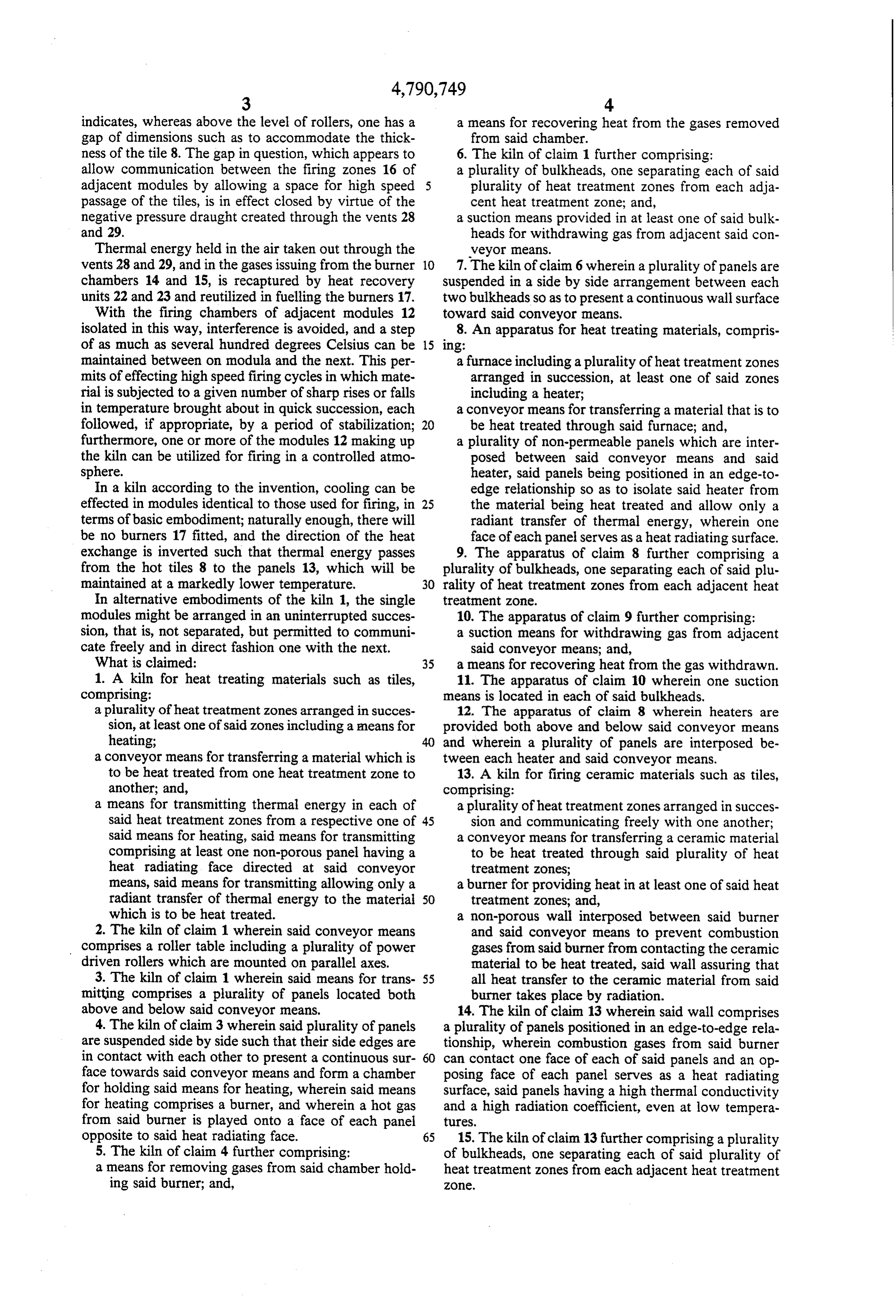
modules might be arranged in an uninterrupted succes 10. The apparatus of claim 9 further comprising: sion, that is, not separated, but permitted to communi a suction means for withdrawing gas from adjacent cate freely and in direct fashion one with the next. said conveyor means; and, What is claimed: 35 a means for recovering heat from the gas withdrawn. 1. A kiln for heat treating materials such as tiles, 11. The apparatus of claim 10 wherein one suction comprising: means is located in each of said bulkheads. a plurality of heat treatment zones arranged in succes 12. The apparatus of claim 8 wherein heaters are sion, at least one of said zones including a means for provided both above and below said conveyor means heating; and wherein a plurality of panels are interposed be a conveyor means for transferring a material which is tween each heater and said conveyor means. to be heat treated from one heat treatment zone to 13. A kiln for firing ceramic materials such as tiles, another; and, comprising:
a means for transmitting thermal energy in each of a plurality of heat treatment zones arranged in succes said heat treatment zones from a respective one of 45 sion and communicating freely with one another; said means for heating, said means for transmitting a conveyor means for transferring a ceramic material comprising at least one non-porous panel having a to be heat treated through said plurality of heat heat radiating face directed at said conveyor treatment zones;
means, said means for transmitting allowing only a a burner for providing heat in at least one of said heat radiant transfer of thermal energy to the material 50 treatment Zones; and, which is to be heat treated. a non-porous wall interposed between said burner 2. The kiln of claim 1 wherein said conveyor means and said conveyor means to prevent combustion comprises a roller table including a plurality of power gases from said burner from contacting the ceramic driven rollers which are mounted on parallel axes. material to be heat treated, said wall assuring that 3. The kiln of claim 1 wherein said means for trans 55 all heat transfer to the ceramic material from said mitting comprises a plurality of panels located both burner takes place by radiation. above and below said conveyor means. 14. The kiln of claim 13 wherein said wall comprises 4. The kiln of claim 3 wherein said plurality of panels a plurality of panels positioned in an edge-to-edge rela are suspended side by side such that their side edges are tionship, wherein combustion gases from said burner in contact with each other to present a continuous sur can contact one face of each of said panels and an op face towards said conveyor means and form a chamber posing face of each panel serves as a heat radiating for holding said means for heating, wherein said means surface, said panels having a high thermal conductivity for heating comprises a burner, and wherein a hot gas and a high radiation coefficient, even at low tempera from said burner is played onto a face of each panel tures.
opposite to said heat radiating face. 65 15. The kiln of claim 13 further comprising a plurality 5. The kiln of claim 4 further comprising: of bulkheads, one separating each of said plurality of a means for removing gases from said chamber hold heat treatment zones from each adjacent heat treatment
Page 6
16. The kiln of claim 15 further comprising a suction comprising a means for removing gases from said cham means for withdrawing gases from adjacent said con ber.
veyor means. 19. The kiln of claim 18 further comprising a means for recovering heat from the gases removed from the 17. The kiln of claim 16 further comprising a means chamber.
for recovering heat from the gases withdrawn. 20. The kiln of claim 13 wherein burners are provided 18. The kiln of claim 15 wherein said wall extends both above and below said conveyor means and between two adjacent ones of said plurality of bulk wherein a wall is interposed between each burner and said conveyor means.
heads to enclose the burner in a chamber and further 10 g k k k
Page 7
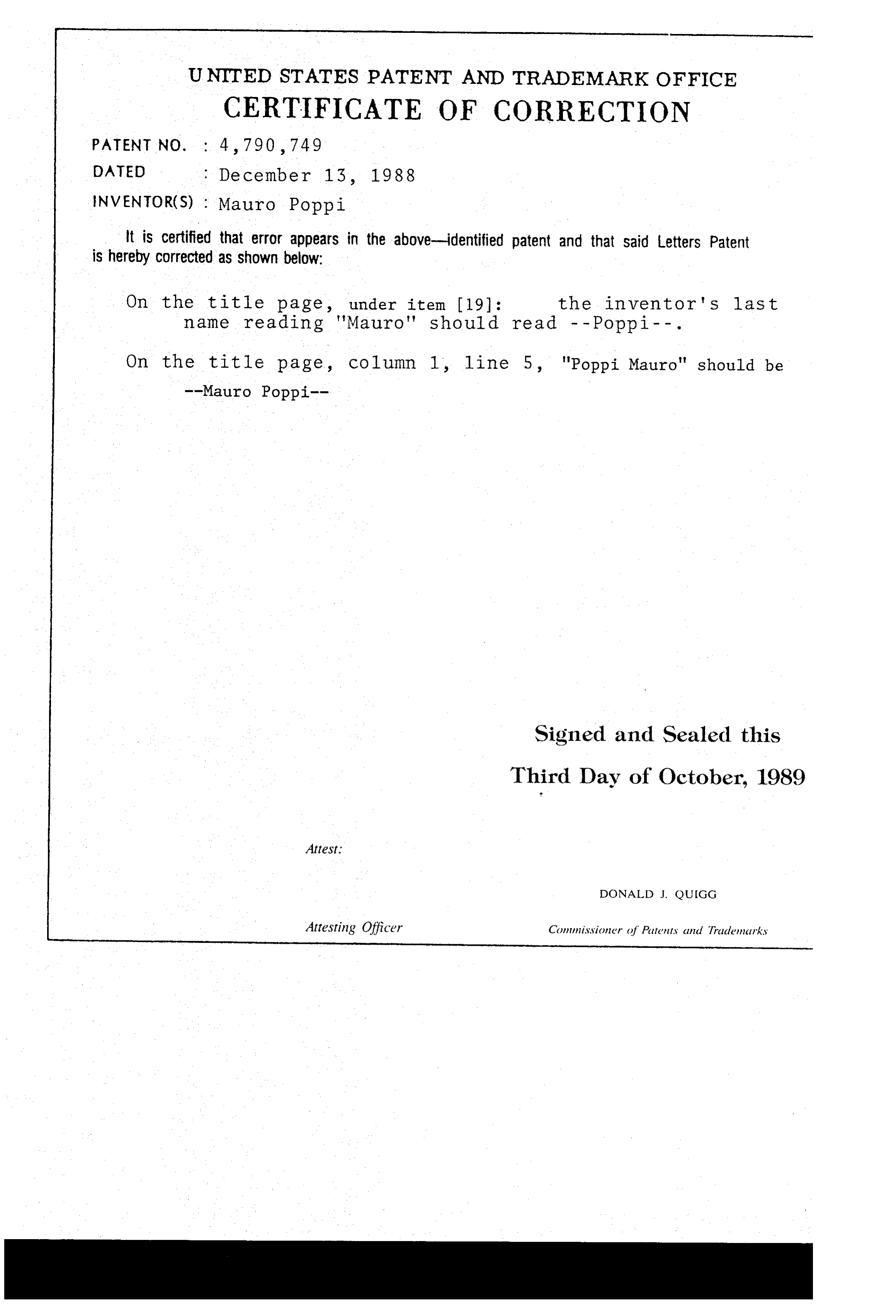
UNITED STATES PATENT AND TRADEMARK OFFICE
CERTIFICATE OF CORRECTION
INVENTOR(S) : Mauro Poppi
It is certified that error appears in the above-identified patent and that said Letters Patent is hereby Corrected as shown below:
On the title page, under item (19): the inventor's last name reading "Mauro" should read - - Poppi - - .
On the title page, column 1, line 5, "Poppi Mauro" should be --Mauro Poppi
Signed and Sealed this
Third Day of October, 1989
Attest.
DONALD J. QUIGG
Attesting Officer Commissioner of Patents and Trademarks
Provenance
- Collection
- Cited prior art
- Original PDF
- patentimages.storage.googleapis.com →
- Filed
- 1987-12-11
- Pages
- 7
- Method
- pdftotext (the PDF's own text layer) + pdftoppm 300dpi page scans
- Source
- Google Patents bibliographic record
- Granted
- 1988-12-13
- Inventors
- Poppi Mauro; Poppi SpA
- Transcribed from
- patentimages.storage.googleapis.com →