patent · US4406261
Intake air flow rate control system for an internal combustion engine of an automotive vehicle
27 September 1983
Page 1 — bibliographic record
United States Patent (19) 11) 4,406,261 Ikeura 45) Sep. 27, 1983 (54) INTAKE AIR FLOW RATE CONTROL . 4,237,833 12/1980 Des Lauriers ...................... 123/339 SYSTEM FOR AN INTERNAL COMBUSTION 3. 13, 3. sigawa is a a so a w w a E,3. ENGINE OF AN AUTOMOTI VE at W Yano . . . . . . . . . . . . . . . . . . . . . . . . . . . . . . . . . . . VE VEHICLE 4,242,994 l/1981 Keely .................................. 123/339 75 Inventor: Kenji Ikeura, Yokosuka, Japan 4,291,656 9/1981 Miyagi ................................ 123/339 73) Assignee: Nissan Motor Company, Limited, 4,336,779 619. SemenceC . . . . . . . . . . . . . . . . . . . . . . . . . . . . . 123/339
Kanagawa, Japan FOREIGN PATENT DOCUMENTS 21 Appl. No.: 152,094 1339404 12/1973 United Kingdom................ 123/339
22 Filed: May 21, 1980 . 1546880 5/1979 United Kingdom................ 123/339 (30) Foreign Application Priority Data 1547915 6/1979 United Kingdom ................ 123/339 May 25, 1979 JP Japan .................................. 54.64340 Primary Examiner-Ronald B. Cox 51) Int. Cl. .............................................. F02D 11/10 Attorney, Agent, or Firm-Lowe, King, Price & Becker 52 U.S. Cl. .................................... 123/339; 180/170; 57 ABSTRACT 123/328; 123/340;74/850 Disclosed herewith an intake air flow rate control sys 58 Field of Search ....................... 123/340,339, 328; tem for an internal combustion engine including a 180/170; 74/850 means for detecting acceleration and deceleration of the (56) References Cited vehicle and controlling the air flow rate in response to
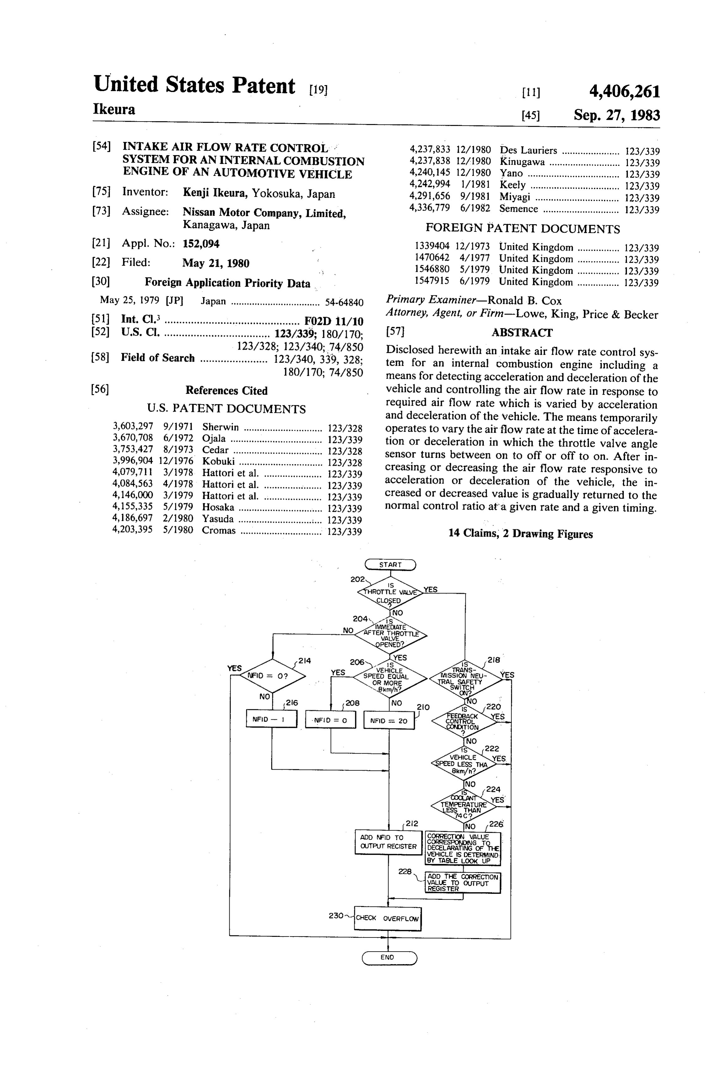
and deceleration of the vehicle. The means temporarily 3,603,297 9/1971 Sherwin .............................. 123/328 operates to vary the air flow rate at the time of accelera 3,670,708 6/1972 Ojala ..... ... 123/339 tion or deceleration in which the throttle valve angle 3,753,427 8/1973 Cedar ... ... 123/328 sensor turns between on to off or off to on. After in 3,996,904 12/1976 Kobuki ......... ... 123/328 creasing or decreasing the air flow rate responsive to 4,079,711 3/1978. Hattori et al. ... ... 123/339 4,084,563 4/1978 Hattori et al. ... ... 123/339 acceleration or deceleration of the vehicle, the in 4,146,000 3/1979 Hattori et al. ... 123/339 creased or decreased value is gradually returned to the 4,155,335 5/1979 Hosaka ...... ... 23/339 normal control ratio at a given rate and a given timing. 4,186,697 2/1980 Yasuda .. ... 123/339 4,203,395 5/1980 Cromas ..... ... 123/339 14 Claims, 2 Drawing Figures
VEHICLE
SPEED EQUAL
DECELARATING OF HE
WEHICLE IS DEERMIND
BY TALE look UP
CHECK OWERFLOW
Page 2
Drawing sheet — no readable text.
Page 3
MMEDIATE
AFTER THROTTLE
VALVE
SPEED EQUAL
OR MORE TRAL SAFETY
EDBACK
CONTROL
TEMPERATURE
ESS THAN
ADD NFD TO CORRECTION VALUE
OUTPUT RECISTER CORRESPONDING TO
DECELARATING OF THE
VEHICLE IS DETERMIND
BY TABLE LOOK UP
ADD THE CORRECTION
VALUE TO: OUTPUT
REGISTER
CHECK OVERFLOW
Page 4
relative to that of required, delay of response is an in
INTAKE AIR FLOW RATE CONTROL SYSTEM . herent characteristic.
FOR AN INTERNAL COMBUSTON ENGINE OF The present invention is intended to solve the above AN AUTOMOTIVE VEHICLE mentioned difficulties or disadvantages in the prior art by providing an improved system for responding to
BACKGROUND OF THE INVENTION . . . varying of required air flow rate. 1. Field of the Invention
SUMMARY OF THE INVENTION
The present invention relates generally to an intake air flow rate control system for an internal combustion Therefore, it is an object of the present invention to O provide an intake air flow rate control system having an engine of an automotive vehicle. More specifically, the present invention relates to a control system for control improved response characteristics for varying the air flow rate to correspond to required air flow rate due to ling an intake air flow rate in the engine idling condi accelerating tion, wherein the vehicle's transient operating charac or decelerating the vehicle. Another and teristics can be improved in response to variation of 15, is to provide means a specific object of the present invention required air flow rate corresponding to variation in rate through the idleforport temporarily controlling air flow and/or the bypass passage in throttle valve angle of the vehicle. response to opening and closing of the throttle valve.
In recent years, pollution of the atmosphere by nitro According to the present invention, there is provided gen oxides NOx, carbon monoxide CO, gaseous sulfu 20 an intake air flow rate control system for an internal combustion engine including means for detecting an rous acid and the like, as produced in the exhaust gas of engine driving condition and for controlling the air automotive vehicles, has become a serious social prob flow rate in response to required air flow rate which is lem. In addition to this, the price of fuel, i.e. gasoline or petrol, for automotive vehicles, has become higher and varied by the engine driving condition. The means tem higher, because of the limited resources thereof. For 25 porarily operates to vary the air flow rate at the time of acceleration or deceleration in which the throttle valve preventing atmospheric pollution caused by exhaust angle sensor turns from ON to OFF or from OFF to gases of automotive vehicles and for economic usage of ON.
fuel, it has become necessary for current automotive Preferably, after once operating the means to control vehicles to control engine speed accurately even when the vehicle engine is idling. . . ,, 30 the air flow rate so as to adapt to the required rate, the In an air flow rate control system, when the vehicle increasedratio value is gradually returned to the normal starts driving after idling, required air flow rate through control
The other at a given rate and a given timing.
objects and advantage sought in the pres an idle port passage and a bypass passage for delivery to ent invention will become the intake manifold of the internal combustion engine is 35 tions given hereinbelow. more apparent from descrip considerably increased. On the other hand, when the vehicle is rapidly decelerated and therefor the throttle BRIEF DESCRIPTION OF THE DRAWINGS valve is completely closed, required air flow rate is The present invention will become more fully under increased a considerable rate. For the conventional control system, it is impossible to follow such substan stood from the detailed description given below, and tial changes in required air flow rate. Therefore, re from the accompanying drawings of the preferred em sponse to change of the required air flow rate is neces bodiment of the present invention, which, however, is sarily delayed. Indeed, in the conventional system, the not be taken as limitative of the present invention in any air flow rate is varied gradually at a given rate to follow way, but is for the purpose of clarification and explana tion only.
the change of required air flow rate. However, when 45 In the drawings:
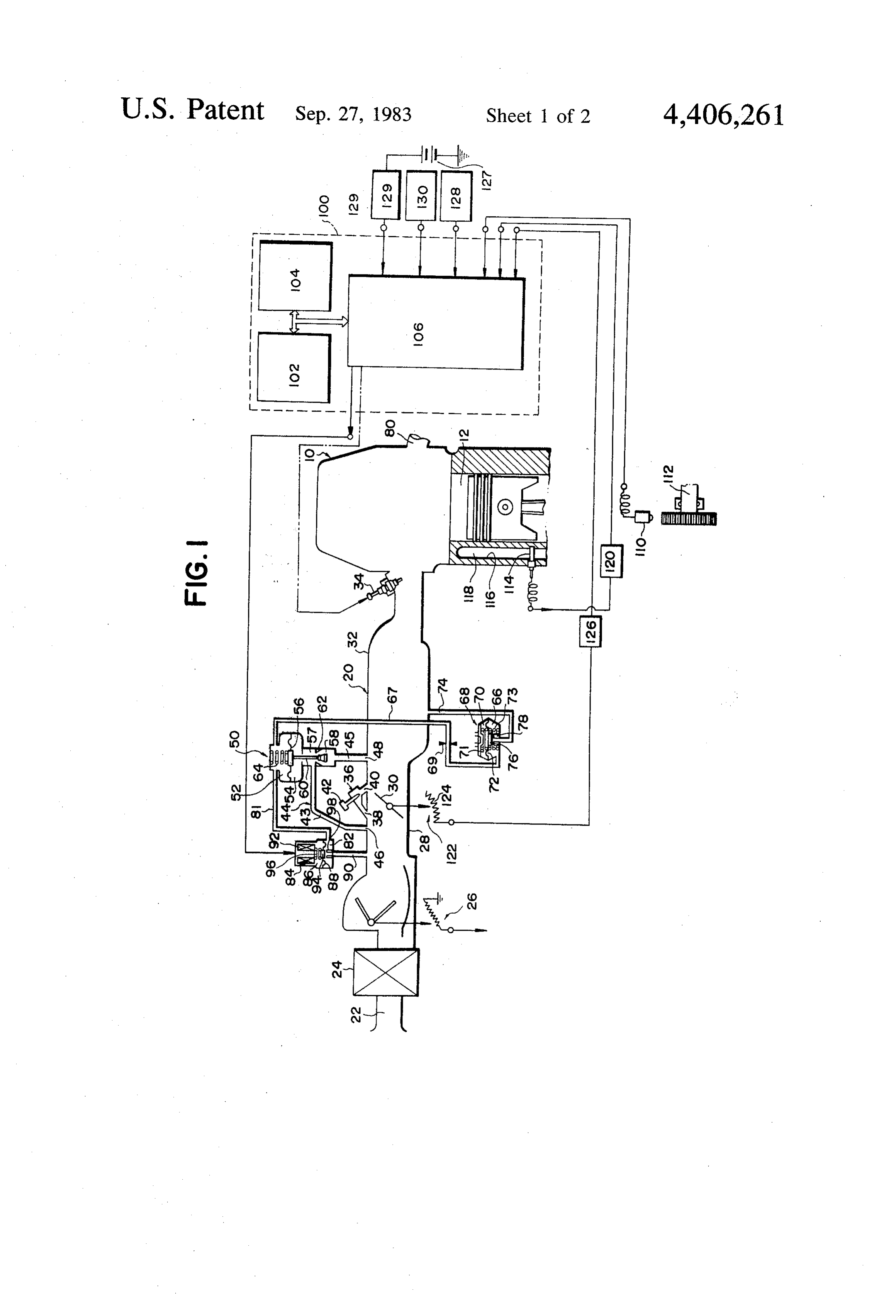
the difference of the air flow rate between the present FIG. 1 is a diagramatical illustration of an intake air rate and the required rate is quite large, particularly flow rate control system for an internal combustion when the required rate is too large relative to the pres engine ent rate, it is impossible for the conventional system to present according invention;
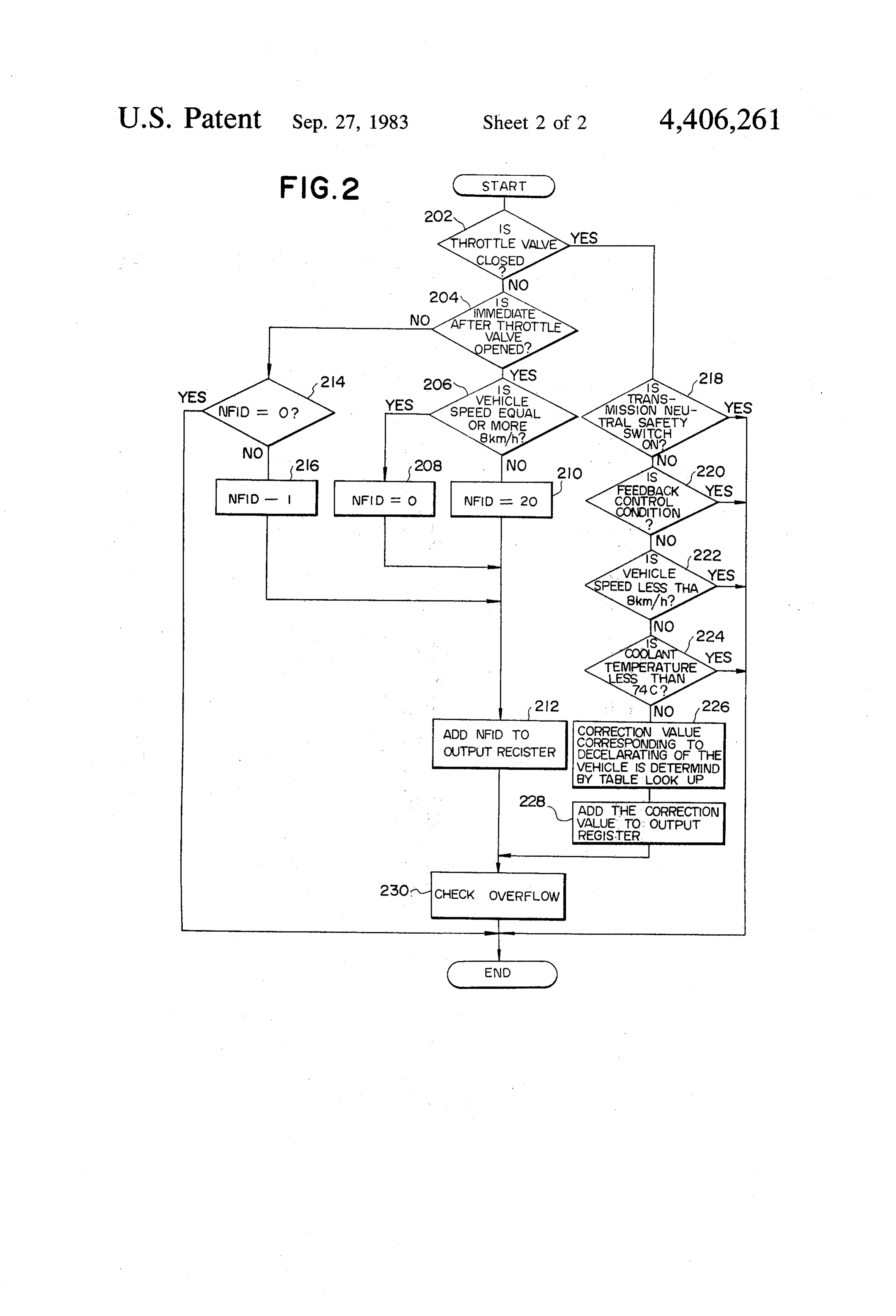
to the preferred embodiment of the and follow the changed requirements rapidly. Therefore, 50 FIG. 2 is a flowchart of a program to be executed by conventional systems may possibly cause engine stalling a microcomputer so as to adjust the control signal in under such circumstances.
On the other hand, in situations of response to in response to acceleration or deceleration of the vehicle. creased air flow rate corresponding to rapid decelera DESCRIPTION OF THE PREFERRED tion of the vehicle, and therefore in response to closure 55 EMBODIMENT of the throttle valve, various systems have been devel Referring now to the drawings, and particularly to oped to improve response characteristics corresponding to change of required air flow rate, such as a so-called FIG. 1, there is shown the general construction of an internal combustion engine having a computer con dash-pot system. In the conventional system, the throt trolled fuel injection system to be provided on an auto tle valve is provided with a bypass passage with a valve motive vehicle. An air flow rate control system accord means which is opened in response to excessive intake ing to the present invention is shown in conjunction vacuum in the intake manifold. In this system, the vac with the specific internal combustion engine as an exam uum in the intake manifold is measured sequentially and ple and for the purposes of explanation only, and should when the vacuum reaches a given value, a control com not be taken as limitative of the scope of the present mand is applied to open the valve means to deliver the 65 invention. Before proceeding with a detailed descrip intake air through the bypass passage. However, in such tion of the invention, it should be appreciated that the a system, since the control for adjusting the air flow rate air flow rate control system according to the present is made in response to exceeding of the air flow rate invention will be applicable to any type of internal com
Page 5
bustion engine which can be controlled by a microcom The chamber 52 of the idle control valve 50 commu puter mounted on the vehicle. nicates with one chamber 66 of a pressure regulating In FIG. 1, each of the engine cylinders 12 of an inter valve 68 as the constant vacuum source through a vac nal combustion engine 10 communicates with an air uum passage 67. The pressure regulating valve 68 is intake passage generally designated by 20. The air in separated into two chambers 66 and 70 by a diaphragm take passage 20 comprises an air intake duct 22 with an 72. The chamber 66 of the pressure regulating valve 68 air cleaner 24 for cleaning atmospheric air, an air flow also communicates with the intake manifold 32, so as to meter 26 provided downstream of the air intake duct 22 introduce vacuum from the intake manifold 32 there to measure the amount of intake air flowing there into, through a passage 74. The chamber 70 is open to through, a throttle chamber 28 in which is disposed a :10 the atmosphere in a well known manner. To the dia throttle valve 30 cooperatively coupled with an accel phragm 72 is secured a valve member 76 which is op erator pedal, not shown, so as to adjust the flow rate of posed to a valve seat 78 provided at the end of the intake air flowing therethrough, and an intake manifold passage 74. In the chambers 66 and 70 there are respec 32 having a plurality of branches not clearly shown in tively disposed helical compression coil springs 71 and FIG. 1. Although not clearly illustrated in FIG. 1, the 15 73. The springs 71 and 73 are generally of equal spring air flow meter is incorporated with another engine con pressure in a position in which the diaphragm 72 is in trol system which determines fuel injection rate, for neutral position. It will be noted that, though it is not so example. A fuel injector 34 is provided on the intake shown, the chamber 66 can also be connected with an manifold 32. The rate of injection of fuel through the exhaust-gas recirculation (EGR) control valve which fuel injector 34, is controlled by an adjusting device, 20 recirculates a part of the exhaust gases flowing through such as, an electromagnetic actuator (not shown). The an exhaust passage 80 to the intake manifold 32. adjusting device is electrically operated by the other The diaphragm 72 is moved upwards or downwards engine control system which determines fuel injection by change of the balance of the vacuum in the chamber rate, fuel injection timing and soon, corresponding to 66 and the atmospheric pressure introduced into the engine condition sensed by various engine parameter 25 chamber 70. By this movement of the diaphragm 72, the sensing means. It should be noted that, although the fuel valve member 76 is moved toward or away from the injector 34 is disposed on the intake manifold 32 in the valve seat 78, so as to regulate a reference vacuum for shown embodiment, it is possible to locate it in the the idle control valve 50. The reference vacuum regu combustion chamber 12 in a well known manner. lated in the pressure regulating valve means 68 is intro An idle port passage 36 is provided opening into the 30 duced to the chamber 52 of the idle adjusting valve throttle chamber 28. One end port 38 of the idle port means 50 through the vacuum passage 67 with an orifice passage 36 opens upstream of the throttle valve 30, and 69. The orifice 69 restricts varying-of vacuum flowing the other end port 40 opens downstream of the throttle into the chamber 52 so as to smooth the valve operation. valve 30, so that the idle port passage 36 bypasses the The chamber 52 of the idle control valve 50 is further throttle valve 30. An idle adjusting screw 42 is provided 35 communicated with a chamber 82 of an intake air valve in the idle port passage 36. The idle adjusting screw 42 84 through an air passage 81. The intake air valve means is manually operable so as to adjust the flow rate of 84 is divided into two chambers 82 and 86 by a dia intake air flowing through the idle port passage 36. A phragm.88. The chamber 82 is also communicated with bypass passage 44 is also provided to the intake air the air intake passage 20-upstream of the throttle valve passage 20. One end 46 of the bypass passage 44 opens 40 30 through a passage 90. An electromagnetic actuator between the air flow meter 26 and the throttle valve 30 92 is disposed within the chamber 86 and is electrically and the other end 48 opens downstream of the throttle operated in response to a train of pulse signals generated valve 30, adjacent to the intake manifold 32. Thus the based on a control signal from the control signal genera bypass passage 44 bypasses the throttle valve 30 and tor in a hereinafter described control unit in use with a connects the section upstream of the throttle valve 30 to 45 microcomputer. On the diaphragm 88 is provided a the intake manifold 32. An idle control valve, generally valve member 94 which is electromagnetically moved designated by 50, is provided in the bypass passage 44. by the actuator 92. In practice, by varying the width, The idle control valve 50 generally comprises two i.e. the pulse duty cycle of the pulse signal, based on the chambers 52 and 54 separated by a diaphragm 56. The control signal, the ratio, of the energized period and chamber 54 communicates with the atmosphere (not 50 deenergized period of the actuator 92 is varied. The shown). The bypass passage 44 is thus separated by the pulse duty is a ratio of the time period of the ON-pulse valve means 50 into two portions 43 and 45 respectively to the period of one cycle of the pulse signal. Therefore located upstream and downstream of the port 57 of the the ratio of the opening period and the closing period of valve 50. The valve means 50 includes a poppet valve the valve 94 is varied so as to control the flow rate of 58 disposed within the portion 57 in a manner that it is 55 the air flowing through the intake air valve 84. In the movable between two position. In one position the chamber 86 there is further provided a helical compres valve is opened to establish communication between the sion coil spring 96 which biases the diaphragm together portions 43 and 45 of the passage 44, and in the other the with the valve member 94 toward the end of the passage valve is closed. The poppet valve element 58 has a stem 90, so as to seat the valve member 94 onto a valve seat 60 whose end is secured to the diaphragm 56 so as to 98 provided at the end of the passage 90. By the vacuum cooperatively move therewith. The diaphragm 56 is from the pressure regulating valve 68, the diaphragm 56 biased downwards in the drawing, so as to release the together with the valve element 58 are moved to con valve element 58 from a valve seat 62, by a helical com trol the flow of air through the bypass passage 44. The pression coil spring 64 disposed within the chamber 52 vacuum in the chamber 52 is controlled with control of the valve means 50. Thereby, the valve 50 is nor 65 ling the flow rate of the air flowing through the intake mally opened, and normally communicates the portions air valve 84 and the air passage 81. :. . 43 and 45 of the bypass passage 44 to one another, via its When the internal combustion engine 10 is in an valve port 57. idling condition, the throttle valve 30 is generally
Page 6
closed so as to ristrict the flow of intake air there ON when the vehicle speed is lower than a given through. Therefore, during idling of the internal com speed, e.g., 8 kph, and is OFF otherwise, bustion engine 10, the intake air substantially flows and a battery voltage signal, fed from the battery 127 through both the idle port passage 36 and the bypass through the A/D converter 129. passage 44, which bypass the throttle valve 30 and con It will be appreciated that, although, in the shown nect the upstream and the downstream areas of the embodiment there is employed a variable resistor 124 in throttle valve 30. Air flow rate through the idle port the throttle valve angle sensor 122 for detecting the passage 36 is adjusted by the idle adjusting screw 42, closed position of the throttle valve, an ON/OFF and the air flow rate through the bypass passage 44 is switch could substitute for the variable registor 124, generally controlled by the idle control valve 50. The 10 which could become ON when the throttle valve 30 is idle control valve 50 is operated by vacuum fed from in the closed position.
the intake manifold 32 through the passage 74, the pres In the air flow rate control system according to the sure regulating valve 68, and the vacuum passage 67. present invention, either feedback control or open loop The vacuum in the chamber 52 is adjusted by the atmo control is selectively carried out corresponding to en spheric intake air flowing thereinto through the passage 15 gine driving condition. In open loop control, a control 90, the electromagnetic valve 84 and the passage 81. signal which determines the pulse signal to be applied to The valve element 58 is operated to control the air flow the actuator 92 is determined corresponding to the en rate through the passage 44 by the vacuum within the gine coolant temperature measured by the coolant tem chamber 52. Since the engine speed depends on the 20 perature sensor 114. On the other hand, in feedback intake air flow rate, it can thus be controlled by control control, the control signal is determined corresponding ling the air flow rate through the idle port passage 36 to an actual engine speed and a difference between the and the bypass passage 44 when the internal combustion actual engine speed and a reference engine speed. In the engine 10 is in the idling condition. - present application, the word "actual engine speed' The control operation for adjusting the intake air 25 should be understood as an engine revolution rate flow rate performed by controlling the electromagnetic within a unit time, in which the rate is measured and actuator 92 is described hereinafter. The controlling of determined based on a signal from the crank angle sen air flow rate, and thus the control of engine speed dur sor 110. Further, the word “reference engine speed” ing idling of the internal combustion engine 10, can also should be understood as a target engine revolution rate be carried out by adjusting the idle adjusting screw 42. within a unit time, in which the rate is basically deter The idle adjusting screw 42 is controlled manually so as 30 mined corresponding to the engine coolant temperature to set the initial engine idling speed. : and is corrected with control parameters indicative of Now, returning to FIG. 1, a microcomputer 100, engine driving condition.
employed for automatically controlling the air flow The intake air flow rate will be corrected under the rate, comprises generally a central processing unit 35 specific driving condition that the throttle valve angle (CPU) 102, a memory unit 104, and an input/output unit sensor 122 detects the throttle valve being opened, and 106 i.e. an interface. As inputs of the microcomputer further detects that the transmission is in driving range, 100, there are provided various sensor signals, such as: the vehicle speed exceeds 8 km/h, the coolant tempera a crank pulse and a crank standard pulse, the crank ture is higher than 74° C. and that open loop control is pulse being generated at every one degree, or at being carried out. The correction of the control signal is other predetermined increments of the crank angle, carried out by way of table look up with respect to the and the crank standard pulse being generated at following correction table relative to the engine speed: every given crank standard angle by a crank angle sensor 110 detecting the amount of rotation of a TABLE crank shaft 1.12; the crank pulse and the crank stan 45 Correction Correction dard pulse are input as an input indicating engine Engine Speed Value Engine Speed Value speed and engine crank position; (r.p.m.) (%) (r.p.m.) (%) a coolant temperature signal, produced by a tempera O O 1600 8.5 ture sensor 114 which is inserted into a coolant 200, O 1800 13 passage 116 provided around the engine cylinder 50 400
112, and exposed to the coolant 118; the tempera 800 O 2400 30 ture sensor 114 generates an analog signal in re 1000 O 2600 35 sponse to the coolant temperature and feeds this 1200 0 2800 40 signal to the input/output unit 106 through an ana 1400 3.5 30002 45 log-digital converter (A/D converter) 120, in 55 which the coolant temperature signal is converted In the above table, the percentage of the correction into a digital code i.e. a binary number signal, value corresponds to the ratio of the increased part of which is suitable as an input for the microcom the duty cycle by correction to the one cycle of a pulse, puter;
a throttle valve angle signal, derived from an analog 60 when the one cycle of a pulse is assumed to be 100%. signal produced by a throttle valve angle sensor the enginecorrecting
In the speed is operation by table look up, when intermediate between two of the 122 which comprises a variable resistor 124 and given speeds the correction rate will be obtained by converted into digital code by an A/D converter interpolation in known manner.
126, Now referring to FIG. 2, there is illustrated a flow a signal from a transmission neutral switch 128, which 65 chart of a program to be excecuted to correct the con is input in the form of an ON/OFF signal, a vehicle speed signal, fed from a vehicle speed sensor trol signal and thereby to correct the air flow rate in response to acceleration and deceleration of the vehicle.
130, which is an ON/OFF signal which becomes When the vehicle speed is more than 8 km/h and addi
Page 7
tionally but essentially, the throttle valve is opened, this until the correction rate NFID becomes 0. Namely, in program is executed to correct the control signal. the shown embodiment, the incremented value of the At first, the throttle valve angle sensor signal is control signal, is decreased by 1 for correction of the checked whether the throttle valve is in closed position, ratio NFID at the block 216, which means that the at a decision block 202. When the throttle valve is incremented pulse duty is decreased at a rate of 0.5%. opened and therefore the decision of the block 202 is Therefore, after incrementation of the pulse duty in NO, the condition is checked at a decision block 204 to response to opening of the throttle valve, the incre determine whether the throttle valve was opened in the mented pulse duty is decreased step by step at a rate of immediate past. If so, at a decision block. 206, the vehi 0.5% per step and the correction rate is made to equal 0 cle speed is checked to determine if it is equal to or 10 by 20 iterations of the program. Here, since, generally, more than 8 km/h. When the vehicle speed is equal to the program is executed per 1 cycle of engine revolu or more than 8 km/h, the incremental or increasing tion, the increased pulse duty is returned to normal rate correction rate NFID for the control signal is set to 0 at after 20 cycles of the engine revolution. By this ap a block 208. While, if the vehicle speed is less than 8 proach, the present control system can fullfill the re km/h and therefore, the decision of the block 206 is NO, 15 quirement for increasing of the intake air flow rate upon the incremental correction rate NFID is set to 20 at a starting driving and for preventing engine stalling due block 210. The correction rate NFID determined at the to lack of the air flow rate by gradually reducing the either block 208 or 210 is added to a value of the control. incremented correction rate.
signal to be sent out to the output register at a block 212. On the other hand, when the vehicle is rapidly decel The duty cycle is determined based on the control sig 20 erated, the correction value rate of the duty cycle is nal in the output register. Therefore the duty cycle is determined at the block 226. Actually, at the block 226, increased corresponding to the increase of the value of the correction value of the control signal is determined, the control signal. and based on the corrected value of the control signal When the decision of the block 204 is NO, i.e., the the duty cycle is determined. For detecting decelerating time of decision at the block 204 is not immediate after 25 the vehicle, the driving condition is checked at respec the throttle being opened, the correction rate NFID is tive blocks 218, 220, 222 and 224. When the transmis checked at a decision block 214 to determine whether it is 0. If the decision of the block 214 is YES, then the sion neutral switch is ON, i.e., the transmission is in process of the program goes to the end of the program. not arise,range, neutral and thus an engine brake condition will it is unnecessary to correct the duty cycle. If
Otherwise, the correction rate NFID is decremented by 30 the neutral switch is OFF but feedback control is taking 1 at a block 216 and thereafter added to the value of the control signal to be sent out to the output register at the place, since it is also unnecessary to correct the duty cycle, the pulse duty cycle will be corrected by the feed block 212.
back control
On the other hand, if the throttle valve is in a closed engine speed and operation corresponding to the actual position, and therefore, the decision at the block 202 is engine speed and thethereference
YES, the transmission neutral switch is checked at a condition, a further correctingengine speed. If in such operation is to take decision block 218 to determine whether it on. If the decision at the block 218 is NO, then decision block 220 place, it will cause an excessive increase of the pulse checks whether the control is carried out by feedback 8duty cycle. Further, when the vehicle speed is less than control. When the decision at the block 220 is NO, the 40 Inkm/h,this an engine braking condition will also not arise.
situation, even if the throttle valve is closed and vehicle speed is checked at a decision block 222 to the neutral switch is OFF, the indication is that the determine whether it is less than 8 km/h a decision block 222. If the vehicle speed is equal to or more than vehicle is being decelerated without engine braking. 8 km/h, and therefore, the decision at the block 222 is Additionally, when the coolant temperature is lower NO, the coolant temperature is checked to determine 45 than 74 C., correction of the duty cycle will take place corresponding to the coolant temperature. Therefore, it whether it is or is not less than 74, at a decision block is unnecessary to increment the duty cycle depending 224. If the decision at the block 224 is NO, the table for determining the correction rate corresponding to decel on deceleration of the vehicle. As stated above, if the eration of the vehicle is looked up to determine the combination of conditions occurs wherein the neutral correction rate corresponding to the engine speed, at a 50 switch is OFF, the feedback control is not taken place, block 226. Thereafter, the correction rate determined at vehicle speed is equal to or more than 8 km/h and the the block 226 is added to the value of the control signal coolant temperature is equal to or higher than 74 C., to be sent out to the output register at a block 228. then correction by table look up takes place at the block Meanwhile, if any of the decisions at the blocks 218, 226. However, although in the shown embodiment the 220, 222 and 224 is YES, the program goes to the end. 55 correction rate is determined by table look up, it will be After processing at the block 212 or 228, the value of possible to obtain the correction rate otherwise, for the control signal to be sent out to the output register is example by using, a formula indicative of function rela checked with respect to overflow, at a block 230. tive to the actual engine speed. The numerical value "1' of the correction rate NFID While the specific construction is disclosed herein corresponds to the 0.5% increase of the pulse duty of a 60 above for illustration of the present invention, it will be pulse signal applied to the actuator 92. Therefore, when possible to provide various modification for various the correction rate is determined by increment 20 at the features or elements which comprise the present inven block 210, the pulse duty is actually incremented by tion. Therefore, the present invention should not be 10% of the one pulse cycle which is 100%. The incre limited to the specific embodiment given above and mented pulse duty is thereafter decreased gradually by 65 should be understood to include any modifications decreasing the value of the control signal gradually. which do not depart from the principle of the present The blocks 214 and 216 provide a process for gradually invention. -
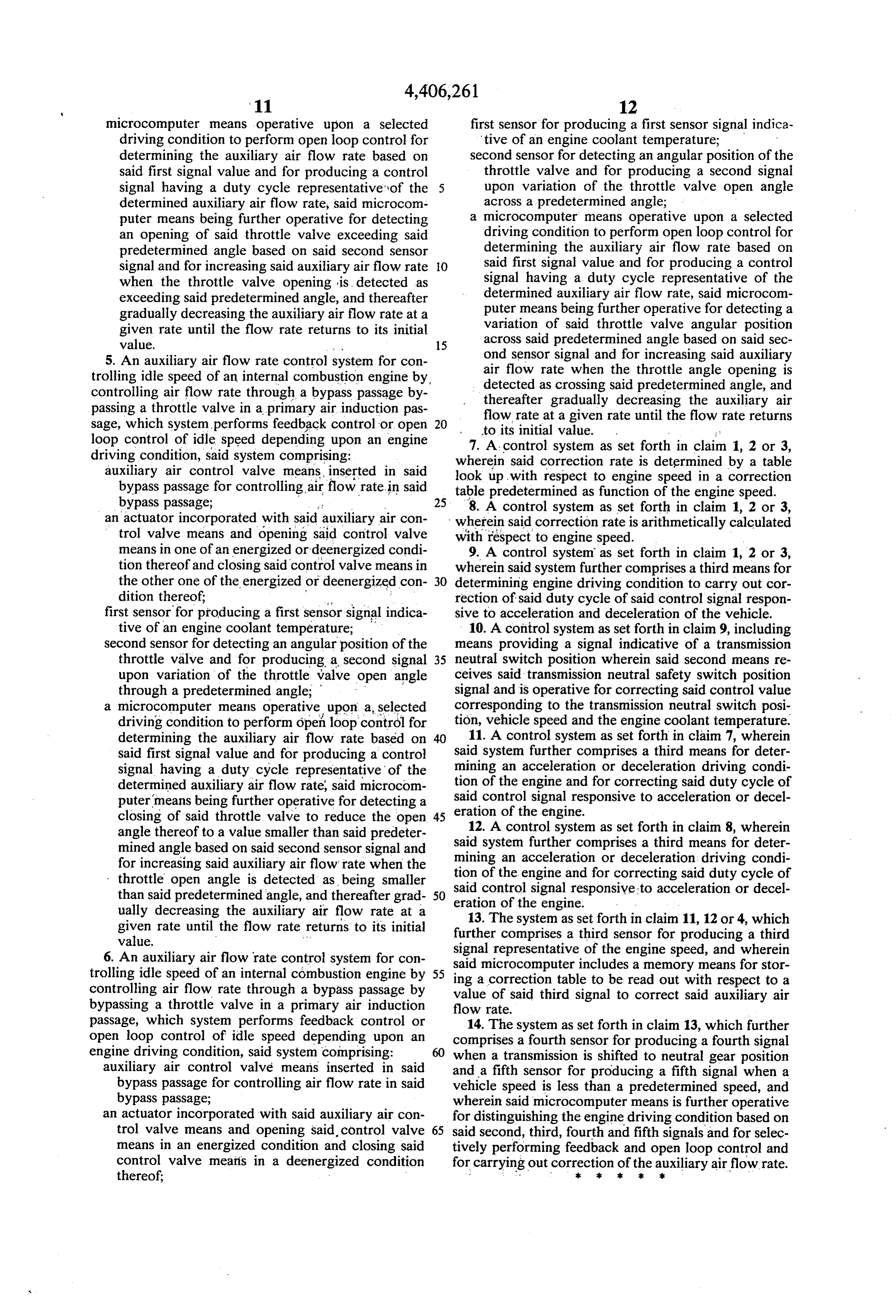
decreasing the incremented value of the control signal What is claimed is:
Page 8
1. An intake air flow rate control system for an inter ter decreasing said increased duty cycle of said nal combustion engine, in which either feedback control control signal at a given rate and a given timing or open loop control for controlling auxiliary air flow until the duty cycle returns to its particular initial rate is selectively carried out corresponding to an en value, gine driving condition, said system including an auxil 5 3. An intake air flow rate control system for an inter iary air flow rate control valve means with an actuator nal combustion engine, in which either feedback control being operative in response to a control signal applied or open loop control for controlling auxiliary air flow
wherein said system comprising: '. rate is selectively carried out corresponding to an en an engine coolant temperature sensor for detecting 10 iary gine driving condition, said system including an auxil engine coolant temperature and producing an en beingairoperative flow rate control valve means with an actuator in response to a control signal applied gine coolant temperature signal indicative of the thereto, detected engine coolant temperature; wherein said system comprising: a throttle angle sensor responsive to a throttle valve angular position smaller than a predetermined open 15 anengine engine coolant temperature sensor for detecting an coolant temperature and producing an en angle for producing a throttle angle signal; gine coolant temperature signal indicative of the a first means for determining a control value in open detected engine coolant temperature; loop control based on the engine coolant tempera a throttle angle sensor responsive to a throttle valve ture signal and for providing to said control signal angular position smaller than a predetermined open a duty cycle indicative of said control value for 20 angle for producing a throttle angle signal; controlling the ratio of energized and deenergized periods of said actuator, said control signal being an engine speed sensor for detecting engine speed and provided a particular duty cycle as an initial value; producing an engine speed signal indicative of the second means, responsive to said throttle angle. a first detected engine speed;
signal, for correcting said control value in response 25 means for determining a control value in open to variation of the throttle valve angular position, loop control based on the engine coolant tempera said second means correcting said control value for ture signal and for providing to said control signal increasing said duty cycle of said control signal at a duty. cycle indicative of said control value for a given rate responsive to an opening of said throt controlling the ratio of energized and deenergized tle valve exceeding said predetermined open angle 30 periods of said actuator, said control signal having and for thereafter gradually decreasing said in a particular duty cycle as an initial value; creased duty cycle of said control signal at a given second means, responsive to said throttle angle rate and a given timing until the duty cycle returns signal and to said engine speed signal, for correct to its initial value. ing said control value in response to variation of 2. An intake air flow rate control system for an inter 35 the throttle valve angular position, said second nal combustion engine, in which either feedback control means correcting said control value for increasing or open loop control for controlling auxiliary air flow said duty cycle of said control signal at a given rate, rate is selectively carried out corresponding to an en which correction rate is a function of an engine gine driving condition, said system including an auxil speed signal value, responsive to a closing condi iary air flow rate control valve means with an actuator tion of said throttle valve angular position in which being operative in response to a control signal applied the angular position of said throttle valve is smaller thereto, than said predetermined open angle, and for there wherein said system comprising: after decreasing said increased duty cycle of said an engine coolant temperature sensor for detecting an control signal at a given rate and a given timing engine coolant temperature and producing an en 45 until the duty cycle returns to the particular initial gine coolant temperature signal indicative of the value.
detected engine coolant temperature; 4. An auxiliary air flow rate control system for con a throttle angle sensor responsive to a throttle valve trolling idle speed of an internal combustion engine by angular position smaller than a predetermined open controlling air flow rate through a bypass passage by ... angle for producing a throttle angle signal; 50 passing a throttle valve in a primary air induction pas a first means for determining a control value in open sage, which system performs feedback control or open loop control based on the engine coolant tempera loop control of idle speed depending upon an engine ture signal and for providing to said control signal driving condition, said system comprising: a duty cycle indicative of said control value for auxiliary air control valve means inserted in said controlling the ratio of energized and deemergized 55 bypass passage for controlling air flow rate in said periods of said actuator, said control signal being bypass passage;
provided at a particular duty cycle as an initial an actuator incorporated with said auxiliary air con value; trol valve means and opening said control valve second means, responsive to said throttle angle means in one of an energized or deenergized condi signal, for correcting said control value in response tion thereof and closing said control valve means in to variation of the throttle valve angular position, the other one of the energized ordeenergized con said second means correcting said control value for dition thereof;
increasing said duty cycle of said control signal at first sensor for producing a first sensor signal indica a given rate, which correction rate is a function of tive of an engine coolant temperature; engine speed, responsive to a closing condition of 65 second sensor for detecting an angular position of the said throttle valve angular position in which the throttle valve and for producing a second signal angular position of said throttle valve is smaller . upon variation of the throttle valve open angle than the predetermined open angle, and for thereaf. through a predetermined angle;
Page 9
microcomputer means operative upon a selected first sensor for producing a first sensor signal indica driving condition to perform open loop control for tive of an engine coolant temperature; determining the auxiliary air flow rate based on second sensor for detecting an angular position of the said first signal value and for producing a control throttle valve and for producing a second signal signal having a duty cycle representative of the upon variation of the throttle valve open angle determined auxiliary air flow rate, said microcom across a predetermined angle; puter means being further operative for detecting a microcomputer means operative upon a selected an opening of said throttle valve exceeding said driving condition to perform open loop control for predetermined angle based on said second sensor determining the auxiliary air flow rate based on signal and for increasing said auxiliary air flow rate O said first signal value and for producing a control when the throttle valve opening is detected as signal having a duty cycle representative of the exceeding said predetermined angle, and thereafter determined auxiliary air flow rate, said microcom gradually decreasing the auxiliary air flow rate at a puter means being further operative for detecting a given rate until the flow rate returns to its initial variation of said throttle valve angular position value. - 15 across said predetermined angle based on said sec 5. An auxiliary air flow rate control system for con ond sensor signal and for increasing said auxiliary trolling idle speed of an internal combustion engine by, air flow rate when the throttle angle opening is controlling air flow rate through a bypass passage by detected as crossing said predetermined angle, and passing a throttle valve in a primary air induction pas thereafter gradually decreasing the auxiliary air sage, which system performs feedback control or open 20 flow rate at a given rate until the flow rate returns
loop control of idle speed depending upon an engine 7. A control system as set forth in claim 1, 2 or 3, driving condition, said system comprising: wherein said correction rate is determined by a table auxiliary air control valve means inserted in said look up, with respect to engine speed in a correction bypass passage for controlling airflow rate in said table predetermined as function of the engine speed. bypass passage; 25 8. A control system as set forth in claim 1, 2 or 3, an actuator incorporated with said auxiliary air con wherein said correction rate is arithmetically calculated trol valve means and opening said control valve with respect to engine speed.
means in one of an energized ordeenergized condi 9. A control system as set forth in claim 1, 2 or 3, tion thereof and closing said control valve means in wherein said system further comprises a third means for the other one of the energized ordeenergized con 30 determining engine driving condition to carry out cor dition thereof; rection of said duty cycle of said control signal respon first sensor for producing a first sensor signal indica sive to acceleration and deceleration of the vehicle. tive of an engine coolant temperature; 10. A control system as set forth in claim 9, including second sensor for detecting an angular position of the means providing a signal indicative of a transmission throttle valve and for producing a second signal 35 neutral switch position wherein said second means re upon variation of the throttle valve open angle ceives said transmission neutral safety switch position through a predetermined angle; signal and is operative for correcting said control value a microcomputer means operative upon a, selected corresponding to the transmission neutral switch posi driving condition to perform open loop control for tion, vehicle speed and the engine coolant temperature. determining the auxiliary air flow rate based on 40 11. A control system as set forth in claim 7, wherein said first signal value and for producing a control said system further comprises a third means for deter signal having a duty cycle representative of the mining an acceleration or deceleration driving condi determined auxiliary air flow rate, said microcom tion of the engine and for correcting said duty cycle of said control signal responsive to acceleration or decel puter means being further operative for detecting a eration closing of said throttle valve to reduce the open 45 of the engine.
angle thereof to a value smaller than said predeter said12.system
A control system as set forth in clain 8, wherein further comprises a third means for deter mined angle based on said second sensor signal and mining an acceleration for increasing said auxiliary air flow rate when the tion of the engine and fororcorrecting deceleration driving condi said duty cycle of throttle open angle is detected as being smaller said control signal responsive to acceleration or decel than said predetermined angle, and thereafter grad 50 ually decreasing the auxiliary air flow rate at a eration of the engine.
13. The system as set forth in claim 11, 12 or 4, which given rate until the flow rate returns to its initial further comprises a third sensor for producing a third 6. An auxiliary air flow rate control system for con signal representative of the engine speed, and wherein
trolling idle speed of an internal combustion engine by 55 said microcomputer includes a memory means for stor controlling air flow rate through a bypass passage by value correction ing a of said table to be read out with respect to a third signal to correct said auxiliary air bypassing a throttle valve in a primary air induction flow rate.
passage, which system performs feedback control or 14. The system as set forth in claim 13, which further open loop control of idle speed depending upon an comprises a fourth sensor for producing a fourth signal engine driving condition, said system comprising: when a transmission is shifted to neutral gear position auxiliary air control valve means inserted in said and a fifth sensor for producing a fifth signal when a bypass passage for controlling air flow rate in said vehicle speed is less than a predetermined speed, and bypass passage; wherein said microcomputer means is further operative an actuator incorporated with said auxiliary air con for distinguishing the engine driving condition based on trol valve means and opening said control valve 65 said second, third, fourth and fifth signals and for selec means in an energized condition and closing said tively performing feedback and open loop control and control valve means in a deenergized condition for carrying out correction of the auxiliary airflow rate. thereof; . . . k . . . .
Provenance
- Collection
- Cited prior art
- Original PDF
- patentimages.storage.googleapis.com →
- Filed
- 1980-05-21
- Pages
- 9
- Method
- pdftotext (the PDF's own text layer) + pdftoppm 300dpi page scans
- Source
- Google Patents bibliographic record
- Granted
- 1983-09-27
- Inventors
- Kenji Ikeura; Nissan Motor Co Ltd
- Transcribed from
- patentimages.storage.googleapis.com →