patent · US4159706A
Solar collector comprising an evacuated absorber cover tube
3 July 1979
Page 1 — bibliographic record
United States Patent (19) (11) 4,159,706 Mahdjuri 45) Jul. 3, 1979 (54) soLAR COLLECTOR COMPRISING AN
EVACUATED ABSORBER COVERTUBE
1989,999 2/1935 Niederle ............................... 26/271 2,133,649 10/1938 Abbot ....... ... 126/271 2,213,894 9/1940 Barry ............ ... 126/271 75 Inventor: Faramarz Mahdjuri, Aachen, Fed. 3,227,153 1/1966 Godel et al.. ... 126/271 Rep. of Germany 3,957,029 5/1976 Nozik ........... ... 126/270 3,981,293 9/1976 Gillery ......... ... 126/271 73) Assignee: U.S. Philips Corporation, New York, 3,985,119 10/1976 Oakes, Jr. ........ ... 126/27 N.Y. 4,010,732 3/1977 Sawata et al. ........................ 126/271 (21) Appl. No.: 777,037 Primary Examiner-Albert W. Davis, Jr. 22 Filed: Mar. 14, 1977 Assistant Examiner-James C. Yeung Attorney, Agent, or Firm-Thomas A. Briody; William 30 Foreign Application Priority Data J. Streeter; Rolf E. Schneider
51) Int. Cl’................................................. F24, 3/02 52 U.S. C. ..................................... 126/270; 126/271 A solar collector comprising an evacuated, transparent 58 Field of Search ............... 126/270, 271; 237/1 A; cover tube sealed at its ends and an associated selective 350/1; 60/641; 136/89 absorber, the inner surface of at least one end of the
cover tube being provided with a metallic reflective layer.
1,801,710 4/1931. Abbot ................................... 126/271 6 Claims, 4 Drawing Figures
2 a. ZZZZZZZZZZZZZZZZZZZZZZZZZZZZZZZZZZZZU
aaaaae
are ayes areast as as areer salary sers artsSeries area reas
signs,
Page 2
Drawing sheet — no readable text.
Page 3
Drawing sheet — no readable text.
Page 4
As a result of the provision of a reflective layer on the
SOLAR COLLECTOR COMPRISING AN end face of the cover tube, the heat radiation originating EVACUATED ABSORBER COVERTUBE from the absorber either is not at all taken up by the cover tube or is not radiated by this tube. In a solar
This invention relates to a solar collector, comprising collector comprising an internal absorber, it is sufficient an evacuated, transparent cover tube which is sealed at to provide a reflective layer only on the end face of the its ends and which is provided with a selective heatre cover tube wherethrough the internal absorber has been flective layer on its inner surface along its entire cylin introduced into the cover tube. The cover tube may drical length and over a cross-sectional area of at least also be of a double-walled type. 180 and which is associated with a selective absorber. 10 The reflective layer is preferably made of a metal or Solar collectors serve to convert the major part of the metal alloy having a low thermal emission factor, such radiation spectrum of sunlight into heat and to transfer as gold, silver, aluminium, lead or copper. A metal or a the heat to a transport medium, for example, water. metal alloy having a low heat emission has an emission In order to obtain high efficiency, solar collectors factor e < 0.05. The reflective layer may consist of a should have the following properties as much as possi 15 baked noble metal. Layers of this kind can be deposited ble: w prior to final assembly of the solar collectors. (a) good absorption (absorption factor a 2 0.9) over However, the reflective layer is preferably deposited the whole solar spectrum (N = 0.3 to 2 m). on the end faces only after the evacuation and the seal (b) low emission (emission factore is 0.3) in the range ing of the cover tube. To this end, in a preferred em of heat radiation (A = 3 to 30 pum). 20 bodiment of the solar collector in accordance with the (c) low heat losses due to heat conduction and con invention, a quantity of metal which can be made to vection. evaporate by external heating is preferably provided in (d) low thermal capacity. the cover tube in the vicinity of at least one of the ends. In this respect a selective heat reflective layer is to be When reflectors which extend transversely of the axis understood to mean a layer which is transparent to 25 of the tube are provided at the ends of the cylindrical sunlight (0.3 to 2 pm) and reflective of heat radiation (3 portion of the cover tube, the metal to be evaporated is to 30 pm) and which has an emission factore is 0.3 and provided on the sides of the reflectors which are remote areflective capacity forheatradiationRd 0.7 where(e= from the cylindrical portion.
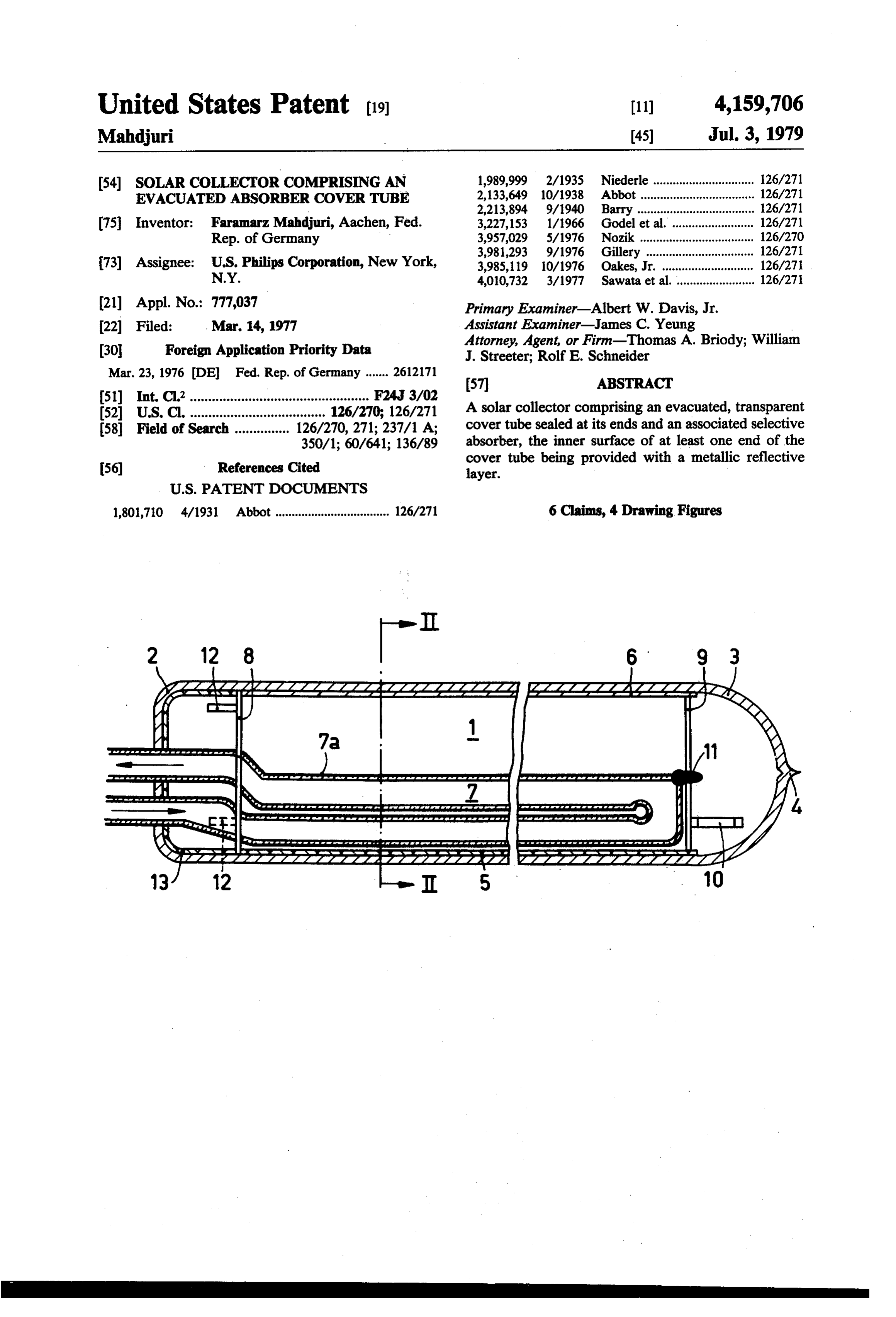
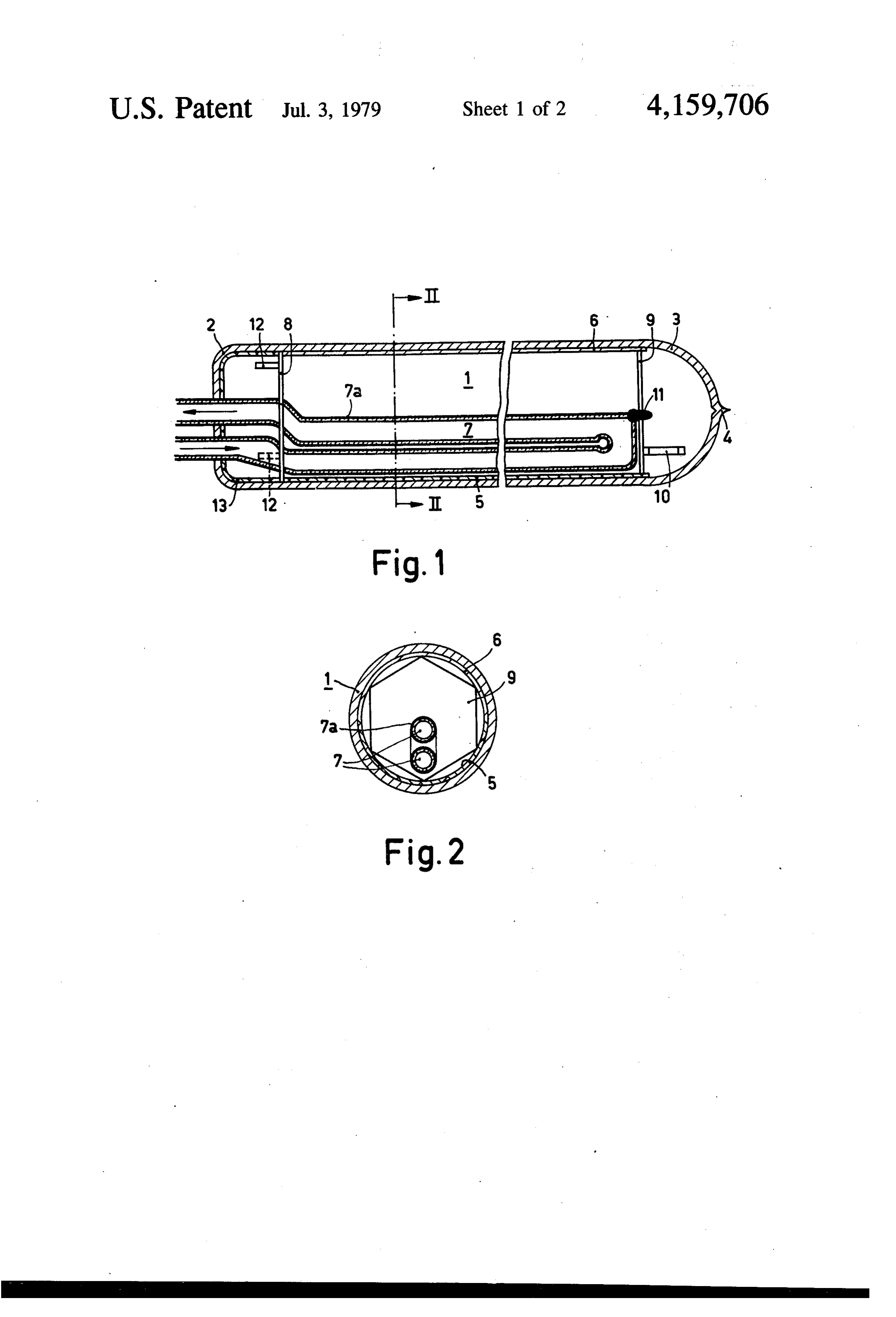
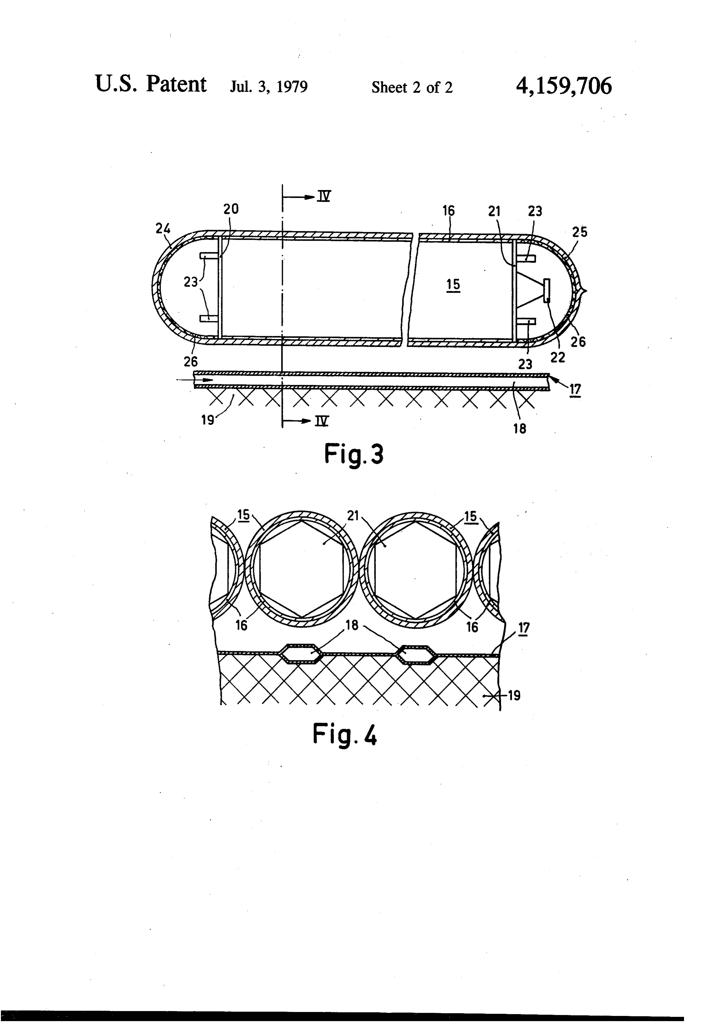
1-R). Heat reflective layers of this kind may be made The invention will now be described in detail herein of gold, silver, tin dioxide or preferably of tin-doped 30 after with reference to two embodiments which are indium oxide. For sunlight (0.3 to 2 um) selective ab diagrammatically shown in the accompanying draw sorbers have an absorption factor a 2 0.85, and for heat ings, in which:
radiation (3 to 30 um) an emission factor e < 0.15. FIG. 1 is a longitudinal sectional view of a solar Selective absorbers of this kind may be made, for exam collector in accordance with the invention, ple, of nickel oxide or copper oxide or of cobalt sul 35 FIG. 2 is a cross-sectional view, taken along the line phide. . . . II-II, of the solar collector shown in FIG. 1. In non-selective absorbers, a 6e 2 0.85. Non-selec FIG. 3 is a longitudinal section view of another solar tive absorbers of this kind are made, for example, of collector in accordance with the invention. black glass enamel. FIG. 4 is a cross-sectional view, taken along the line Solar collectors of the kind set forth are known in 40 IV-V, of the solar collector shown in FIG. 3. which a U-shaped absorber is sealed in an evacuated The solar collector shown in FIGS. 1 and 2 com glass cover tube. Also known are solar collectors in prises a transparent cover tube 1 which is made of glass which a flat absorber is covered by a number of adjoin and which is sealed at its ends, more or less dome ing and contacting evacuated glass tubes. During manu shaped end faces 2 and 3 thus being formed. On the end facture, the cover tubes, provided with a selective heat 45 face 3 there is situated a sealing pumping stem 4 where reflective layer in their cylindrical zones, are sealed at through the interior of the cover tube 1 has been evacu their ends, so that their end faces remain free from any ated to a residual gas pressure of less than 1 millibar. layer whatsoever. However, because the known solar The cover tube 1 is provided with an internal reflective collector with a sealed internal absorber radiates heat layer 5 of vapour-deposited silver along its entire cylin from the end sealing faces of the cover tube, and be 50 drical length and over a cross-sectional area of 180. cause the other known solar collector with various Furthermore, above the reflective layer 5 the cover cover tubes over a flat absorber transfers part of its heat tube 1 is provided on its inner surface, in the cylindrical to the lower halves of the cover tubes, so that this heat zone, with a selective heat-reflective layer 6 which ultimately reaches the noncoated ends of the cover consists of tin-doped In2O3.
tubes by heat conduction, and is subsequently radiated 55 In the end face 2 of the cover tube 1 a tubular ab to the upper half of the ends of the cover tubes, the ends sorber 7 of glass or metal is sealed in a vacuum-tight of the cover tubes which are not provided with a layer manner; this absorber has a U-shaped construction and cause heat losses by radiation. Because glass has a high serves to accommodate a transport medium, for exam emission factor, radiation losses of this kind are compar ple, water, which is to be heated by solar radiation. The atively high, the more so because the ends of the cover central plane of the absorber 7 which extends through tubes which are not provided with a layer represent 5 to the axes of the U-tube is arranged in the plane of sym 10% of the total surface area of the cover tubes. metry of the interior reflective layer 5, between the axis The invention has for its object to eliminate such of the cover tube and the interior reflective layer. In the radiation losses through the ends of the cover tubes. cylindrical zone of the cover tube 1, the absorber in This is achieved in a solar collector of the kind set 65 cludes a black surface layer 7a which consists, for exam forth in that at least one end of the cover tube is pro ple, of black glass enamel.
vided with a metallic reflective layer on its inner sur The absorber 7 is maintained in position in the cover face. tube 1 by means of two flat reflectors 8 and 9. The
Page 5
reflectors extend on both ends of the cylindrical portion 20 and 21 small quantities of metal 23, for example, lead of the cover tube, transversely of the tube axis, and are are provided; these quantities are evaporated by exter made of mica with a vapour-deposited aluminium layer. nal induction heating after the manufacture of the evac The reflector 9 furthermore carries a getter ring 10. A uated cover tube 15. A reflective layer 26 of lead is then glass mandril 11 which engages the reflector 9 in a 5 deposited on the dome-shaped end faces 24 and 25 of supporting manner is fused to the rearmost end of the the cover tubes, the said layer preventing heat radiation absorber 7. inside the cover. tube.
The basic material used for the manufacture of such a In a practical embodiment of a solar collector as solar collector is an open glass tube having a round shown in FIGS. 3 and 4, the diameter of the glass cover section, the interior of the said tube first being provided O tubes 14 amounted to 65 mm, the wall thickness to 1.2 with the layers 5 and 6. The absorber 7 is sealed in on mm and the length to 100 cm. The selective heat-reflec one end of the glass tube. After the mounting of the tive layer 16, made of indium oxide, had a thickness of reflectors 8 and 9, the other end of the tube is closed, 0.3 micron. The absorber 17 had a black cover layer (for and the tube is evacuated and subsequently sealed. example, aquaduct) having a thickness of approximately In order to avoid heat losses from the end face 2, two 15 0.2 mm, an absorption factor a = 0.95 and an emission quantities metal 12 of, for example, aluminium, lead or factor e = 0.8. The distance between the cover tubes 15 copper, are provided on the reflector 8. After evacua and the absorber 17 amounted to 20 mm. The lead re tion of the cover tube 2, it is externally heated by induc flective layer 26 had a thickness of 0.1 micron. When tion in the region of the quantities of metal 12, with the use is made of these cover tubes 15 with a reflective result that the metal 12 evaporates and is deposited as a 20 layer on their ends, a reduction in heat loss of 20% is metallic reflective layer 13 on the end face 2 of the achieved in comparison with cover tubes comprising cover tube 1. The evaporated metal is at the same time uncoated end faces.
also deposited on the absorber tube 7 in the region be What is claimed is:
tween the reflector 8 and the end face 2. This is desir 1. A solar collector, which comprises an evacuated, able to prevent heat radiation from the absorber tube in 25 transparent essentially straight cover tube substantially this region. circular in cross-section and sealed at its ends, a selec The solar collector shown in FIGS. 3 and 4 com tive absorber associated with said cover tube, a selec prises several evacuated glass tubes 15 which are adja tive heat-reflective layer provided on the inner surface cently arranged in contact with each other and whose of said cover tube along its entire cylindrical length and ends are sealed. The glass tubes 15 may be arranged 30 over a cross-sectional area of at least 180, and a metal loosely one against the other or may be interconnected lic reflective layer provided on the inner surface of at by means of glue or fusion. On their inner surface the least one end of the cover tube.
glass cover tubes 15 are provided all around with a 2. A solar collector according to claim 1, in which the selective heat-reflective layer 16 which consists, for metallic reflective layer has a low thermal emission example, of tin-doped In2O3. This layer 16 extends only 35 factor.
along the cylindrical region of the cover tubes 15 for 3. A solar collector according to claim2, in which the manufacturing-technical reasons. metallic reflective layer is formed of gold, silver, alumi The absorber 17 covered by these tubes 15 consists of num, lead or copper.
blackened metal plates which have been cold-welded 4. A solar collector according to claim 1, in which the under pressure, the said plates comprising channel-like 40 metallic reflective layer is formed of a baked noble ducts 18 for the heat transport medium, for example, metal.
water. The absorber 17 may also be provided with a 5. A solar collector according to claim 1, in which the selective absorber layer. The absorber is heat-insulated selective absorber comprises a U-shaped tube extending on its other side by means of an insulating material 19. into the cover tube through said one end, said U-shaped At the ends of the cylindrical portion of the cover 45 tube being in sealing engagement with said one end. tube 15 there are provided reflectors 20 and 21 which 6. A solar collector according to claim 1, in which the extend transversely of the axis of the cover tube and selective absorber comprises a flat plate arranged below which are made of mica with a vapour-deposited alu said cover tube, said flat plate being provided with one minium layer. A getter ring 22 is connected to the re or more tubular channels.
flector 21. Furthermore, in contact with the reflectors 50
Provenance
- Collection
- Patents citing this work
- Pages
- 5
- Method
- pdftotext (the PDF's own text layer) + pdftoppm 300dpi page scans
- Patent office record
- patents.google.com →
- Source
- Google Patents citing-documents table
- Assignee
- U.S. Philips Corporation
- Published
- 1979-07-03
- Transcribed from
- patentimages.storage.googleapis.com →