patent · US4108374
Heat storage water tank
22 August 1978
Page 1 — bibliographic record
United States Patent (19) 11) 4,108,374 Lyon et al. 45) Aug. 22, 1978
(54) HEAT STORAGE WATER TANK Primary Examiner-William F. O'Dea Assistant Examiner-Harold Joyce (75) Inventors: Floyd A. Lyon, Brookville; Henry Attorney, Agent, or Firm-James P. Malone Harrison, Locust Valley, both of
N.Y. 57 ABSTRACT 73) Assignee: Halm Instrument Co., Inc., Glen A heat storage tank suitable for solar house heating Head, N.Y. systems. The tank includes
a supported bottom (21) Appl. No.: 709,587 panel covered with a layer of stones of substantially (22 Filed: Jul. 29, 1976 uniform size which are bonded together thermally and 2 mechanically at their points of contact with each other, 51) Int. C.’.............................................. F24D 11/00 but which have voids forming air passages remaining 52 U.S. Cl. ....................126/27i. %5.6.% between them, bottom insulation below said bottom 58 Field of Search .... 1 %. s: 3./1 A. £6/2. panel, a bottom air passage between the bottom insula 58) Field of Search.... 9 27. 374 26 tion and the bottom panel, and at least one opening in av F is the bottom panel whereby air can pass from said bottom 56) References Cited air passage into said layer of stones.
1,209,956 12/1916 Gesell .............................. 126/271 X 3,369,541 2/1968 Thomason ............................ 126/400 6 Claims, 9 Drawing Figures
N S -- - - - - - -- -ren
CONTROL
N CRCUT 29 - - - -- - - - FG 7
7 . . . . . . . . . . . 7 it 1,24 / 4 S9 '-- - - 2-2 : i. ki, -- - - - Ny.
Ya- S:
N ---
s a R
8 O a.
Yes
2 t in N. Ys" itNao
| Nix N N N. . . 's y is NN w 6
ASE Zo EZEZEZ 77.2 727, 7 A7, e7, a 4 a. 37, so
Page 2
Drawing sheet — no readable text.
Page 3
Drawing sheet — no readable text.
Page 4
Drawing sheet — no readable text.
Page 5
Drawing sheet — no readable text.
Page 6
Drawing sheet — no readable text.
Page 7
surroundings. It is well known that the amount of heat
HEAT STORAGE WATERTANK collector area required by a house heating system which stores heat for an entire year is less than half the collec
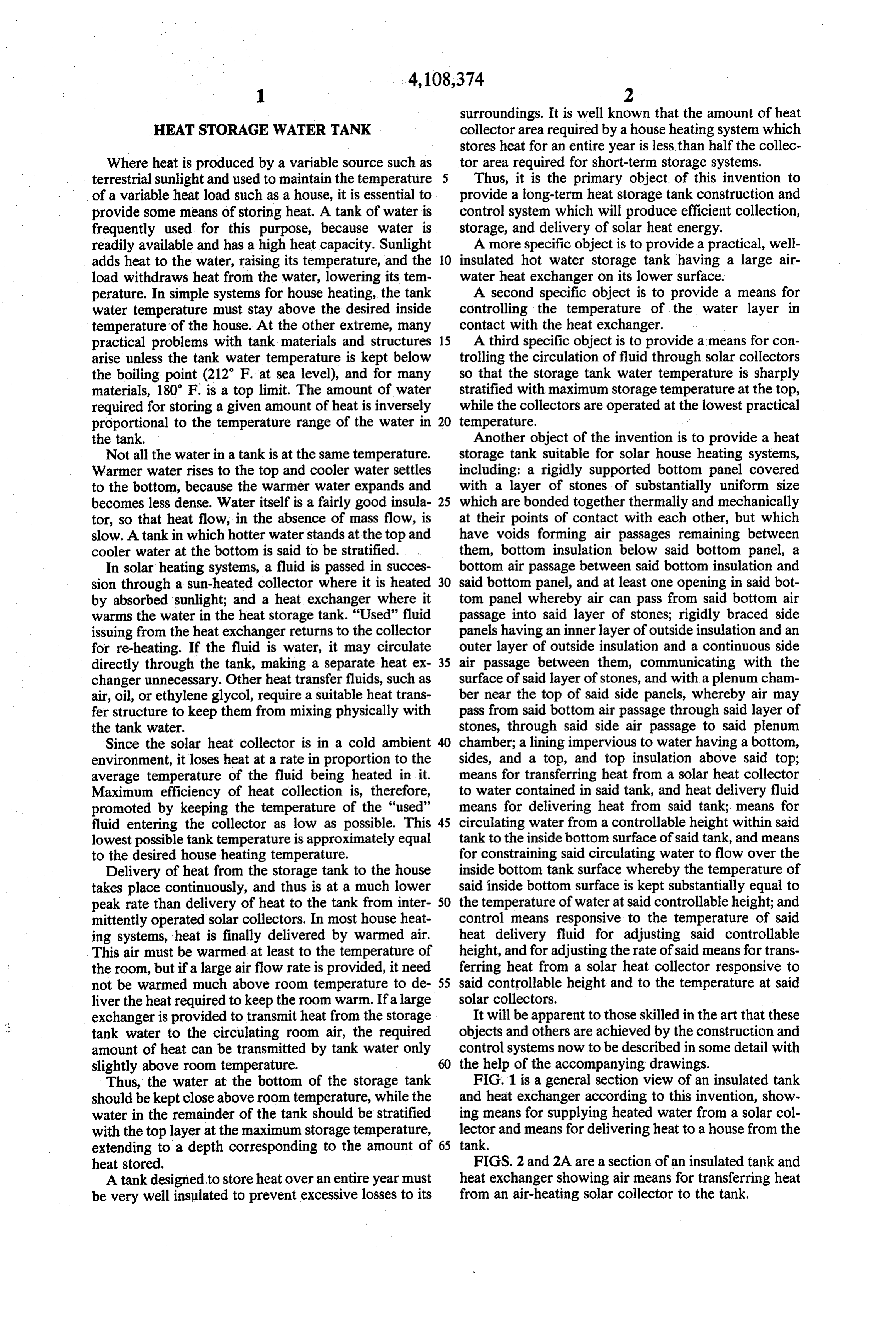
Where heat is produced by a variable source such as tor area required for short-term storage systems. terrestrial sunlight and used to maintain the temperature 5 Thus, it is the primary object of this invention to of a variable heat load such as a house, it is essential to provide a long-term heat storage tank construction and provide some means of storing heat. A tank of water is control system which will produce efficient collection, frequently used for this purpose, because water is storage, and delivery of solar heat energy. readily available and has a high heat capacity. Sunlight A more specific object is to provide a practical, well adds heat to the water, raising its temperature, and the O insulated hot water storage tank having a large air load withdraws heat from the water, lowering its tem water heat exchanger on its lower surface. perature. In simple systems for house heating, the tank A second specific object is to provide a means for water temperature must stay above the desired inside controlling the temperature of the water layer in temperature of the house. At the other extreme, many contact with the heat exchanger.
practical problems with tank materials and structures 15 A third specific object is to provide a means for con arise unless the tank water temperature is kept below trolling the circulation of fluid through solar collectors the boiling point (212 F. at sea level), and for many so that the storage tank water temperature is sharply materials, 180' F. is a top limit. The amount of water stratified with maximum storage temperature at the top, required for storing a given amount of heat is inversely while the collectors are operated at the lowest practical proportional to the temperature range of the water in temperature.
the tank. Another object of the invention is to provide a heat Not all the water in a tank is at the same temperature. storage tank suitable for solar house heating systems, Warmer water rises to the top and cooler water settles including: a rigidly supported bottom panel covered to the bottom, because the warmer water expands and with a layer of stones of substantially uniform size becomes less dense. Water itself is a fairly good insula 25 which are bonded together thermally and mechanically tor, so that heat flow, in the absence of mass flow, is at their points of contact with each other, but which slow. A tank in which hotter water stands at the top and have voids forming air passages remaining between cooler water at the bottom is said to be stratified. . them, bottom insulation below said bottom panel, a In solar heating systems, a fluid is passed in succes bottom air passage between said bottom insulation and sion through a sun-heated collector where it is heated 30 said bottom panel, and at least one opening in said bot by absorbed sunlight; and a heat exchanger where it tom panel whereby air can pass from said bottom air warms the water in the heat storage tank. "Used' fluid passage into said layer of stones; rigidly braced side issuing from the heat exchanger returns to the collector panels having an inner layer of outside insulation and an for re-heating. If the fluid is water, it may circulate outer layer of outside insulation and a continuous side directly through the tank, making a separate heat ex 35 air passage between them, communicating with the changer unnecessary. Other heat transfer fluids, such as surface of said layer of stones, and with a plenum cham air, oil, or ethylene glycol, require a suitable heat trans ber near the top of said side panels, whereby air may fer structure to keep them from mixing physically with pass from said bottom air passage through said layer of the tank water. stones, through said side air passage to said plenum Since the solar heat collector is in a cold ambient chamber; a lining impervious to water having a botton, environment, it loses heat at a rate in proportion to the sides, and a top, and top insulation above said top; average temperature of the fluid being heated in it. means for transferring heat from a solar heat collector Maximum efficiency of heat collection is, therefore, to water contained in said tank, and heat delivery fluid promoted by keeping the temperature of the "used' means for delivering heat from said tank; means for fluid entering the collector as low as possible. This 45 circulating water from a controllable height within said lowest possible tank temperature is approximately equal tank to the inside bottom surface of said tank, and means to the desired house heating temperature. for constraining said circulating water to flow over the Delivery of heat from the storage tank to the house inside bottom tank surface whereby the temperature of takes place continuously, and thus is at a much lower said inside bottom surface is kept substantially equal to peak rate than delivery of heat to the tank from inter 50 the temperature of water at said controllable height; and mittently operated solar collectors. In most house heat control means responsive to the temperature of said ing systems, heat is finally delivered by warmed air. heat delivery fluid for adjusting said controllable This air must be warmed at least to the temperature of height, and for adjusting the rate of said means for trans the room, but if a large air flow rate is provided, it need ferring heat from a solar heat collector responsive to not be warmed much above room temperature to de 55 said controllable height and to the temperature at said liver the heat required to keep the room warm. If a large solar collectors.
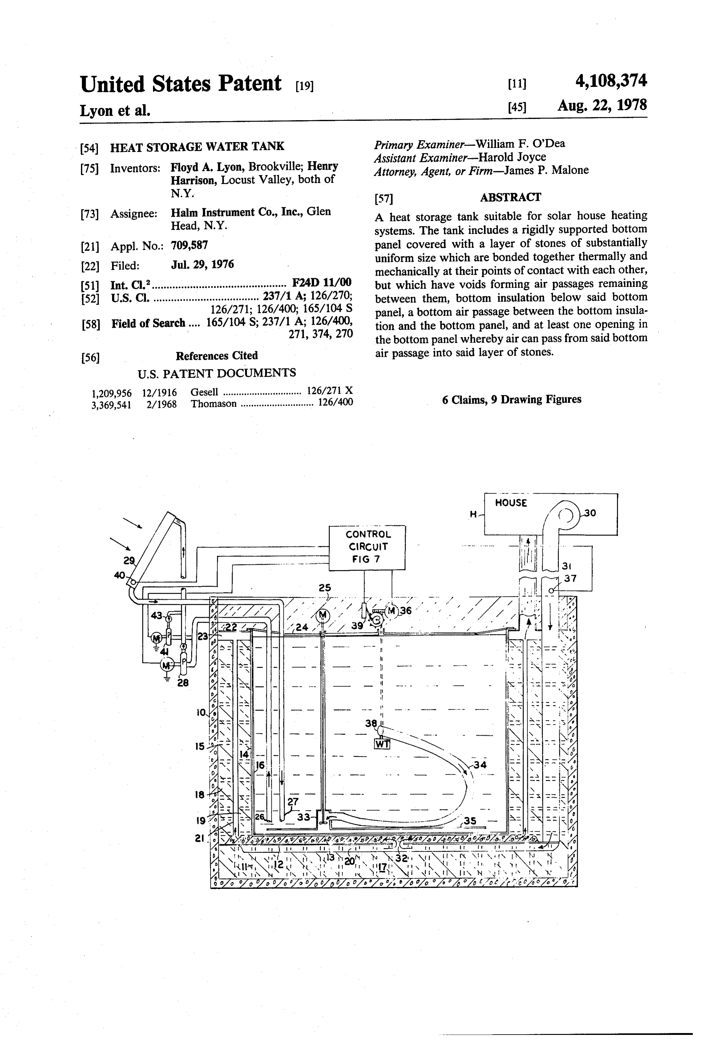
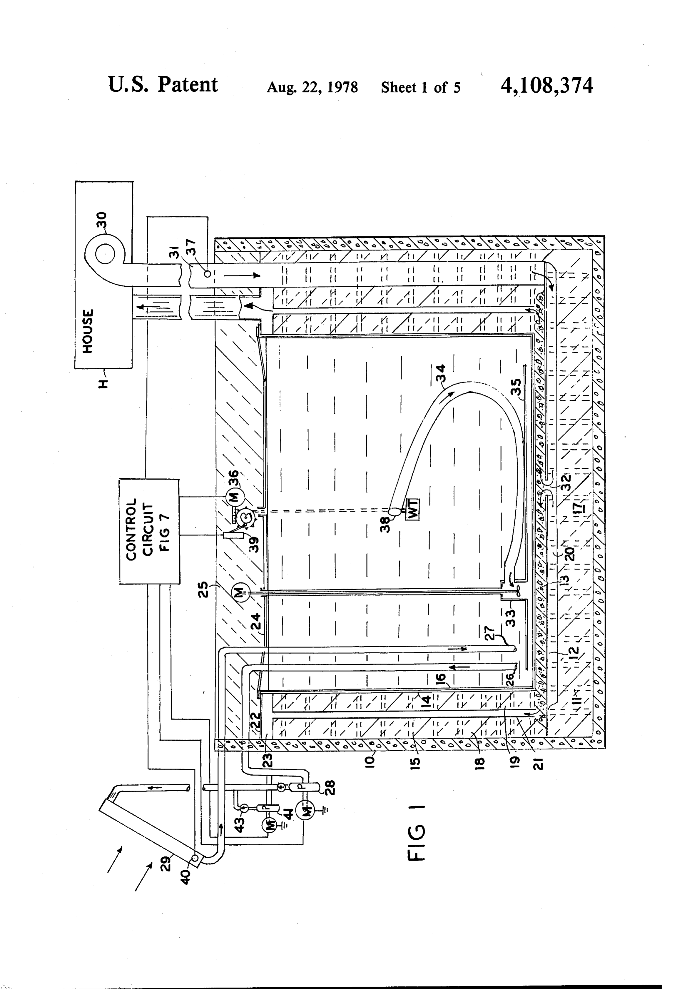
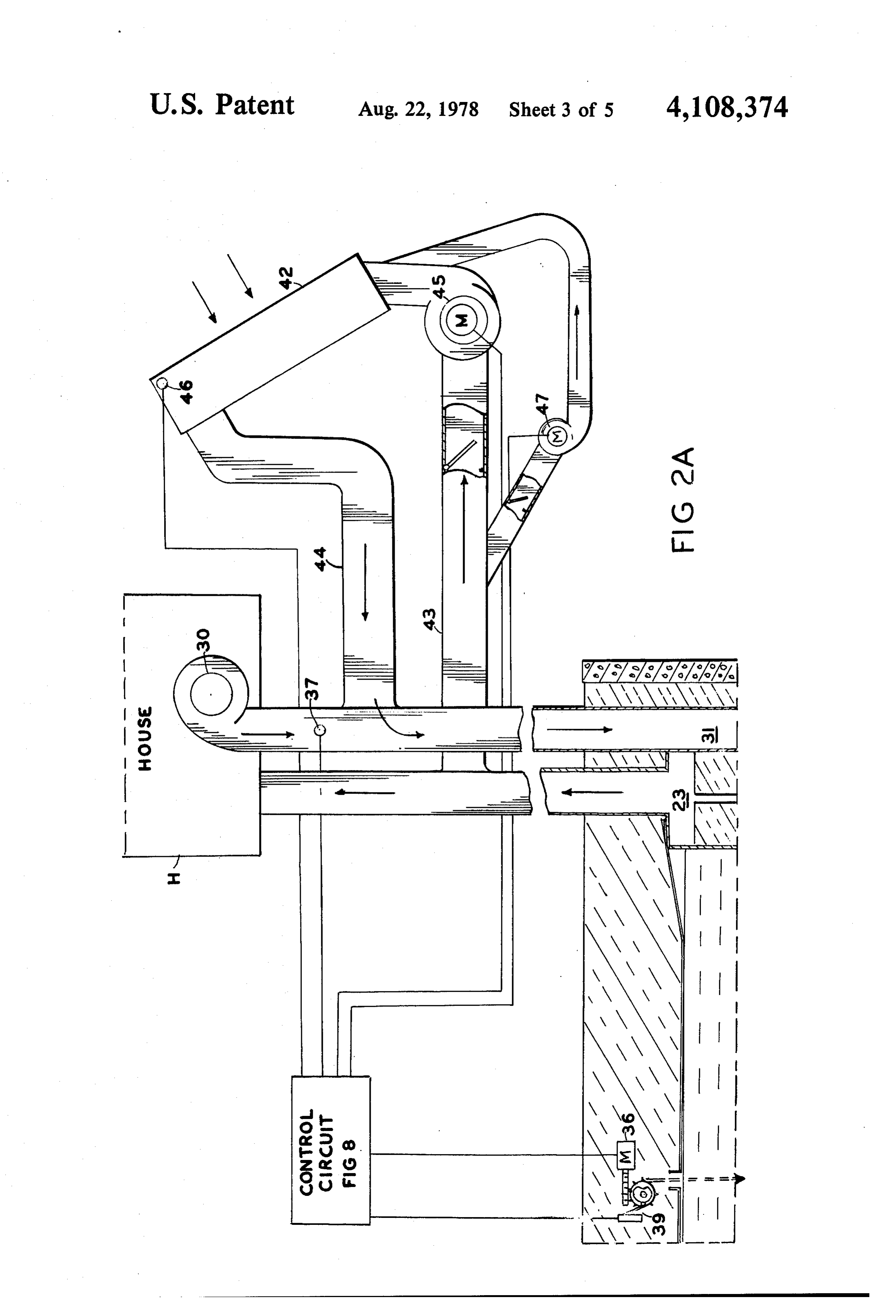
exchanger is provided to transmit heat from the storage It will be apparent to those skilled in the art that these tank water to the circulating room air, the required objects and others are achieved by the construction and amount of heat can be transmitted by tank water only control systems now to be described in some detail with slightly above room temperature. 60 the help of the accompanying drawings. Thus, the water at the bottom of the storage tank FIG. 1 is a general section view of an insulated tank should be kept close above room temperature, while the and heat exchanger according to this invention, show water in the remainder of the tank should be stratified ing means for supplying heated water from a solar col with the top layer at the maximum storage temperature, lector and means for delivering heat to a house from the extending to a depth corresponding to the amount of 65 tank.
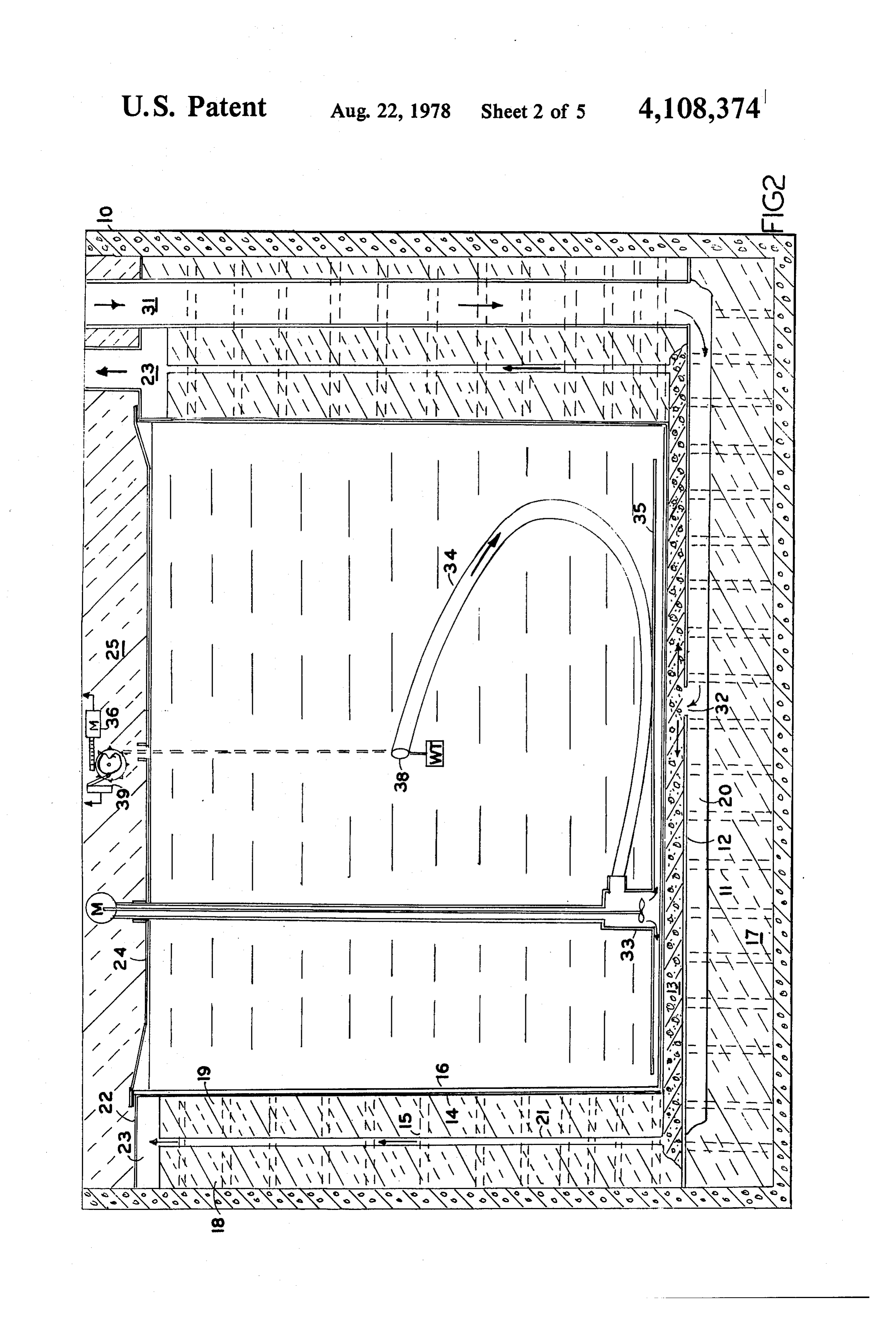
heat stored. FIGS. 2 and 2A are a section of an insulated tank and A tank designed to store heat over an entire year must heat exchanger showing air means for transferring heat be very well insulated to prevent excessive losses to its from an air-heating solar collector to the tank.
Page 8
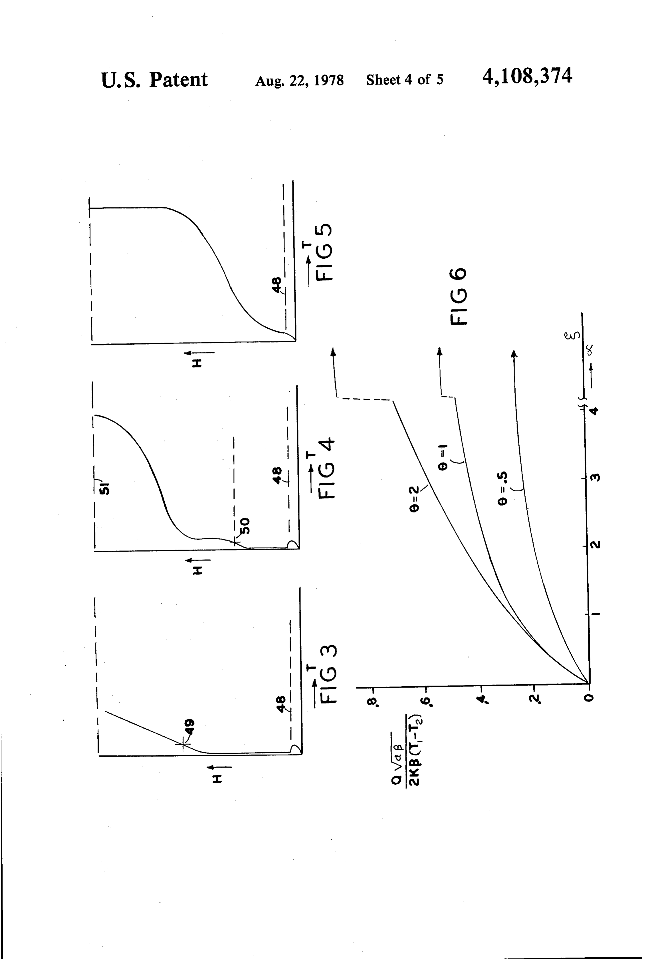
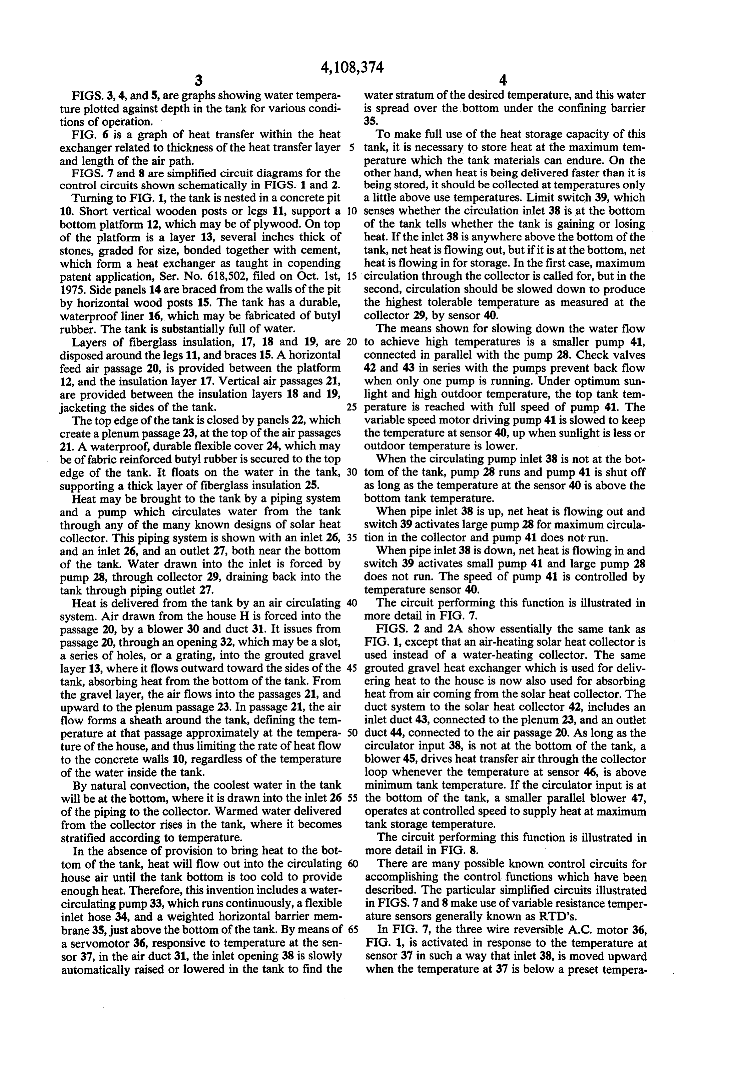
FIGS. 3, 4, and 5, are graphs showing water tempera water stratum of the desired temperature, and this water ture plotted against depth in the tank for various condi is spread over the bottom under the confining barrier tions of operation. 35.
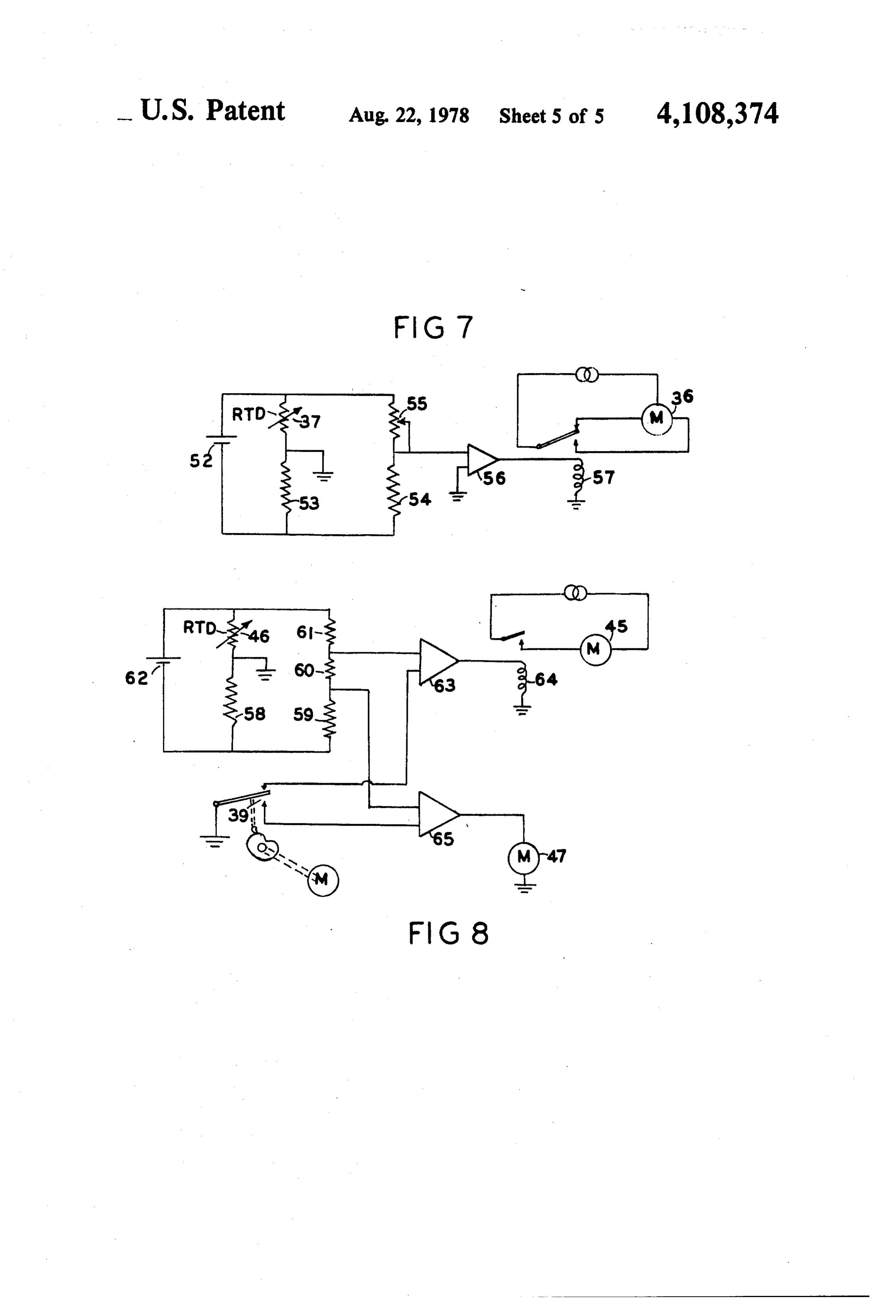
FIG. 6 is a graph of heat transfer within the heat To make full use of the heat storage capacity of this exchanger related to thickness of the heat transfer layer tank, it is necessary to store heat at the maximum tem and length of the air path. perature which the tank materials, can endure. On the FIGS. 7 and 8 are simplified circuit diagrams for the other hand, when heat is being delivered faster than it is control circuits shown schematically in FIGS. 1 and 2. being stored, it should be collected at temperatures only Turning to FIG. 1, the tank is nested in a concrete pit a little above use temperatures. Limit switch 39, which 10. Short vertical wooden posts or legs 11, support a 10 senses whether the circulation inlet 38 is at the bottom bottom platform 12, which may be of plywood. On top of the tank tells whether the tank is gaining or losing of the platform is a layer 13, several inches thick of heat. If the inlet 38 is anywhere above the bottom of the stones, graded for size, bonded together with cement, tank, netheat is flowing out, but if it is at the bottom, net which form a heat exchanger as taught in copending heat is flowing in for storage. In the first case, maximum patent application, Ser. No. 618,502, filed on Oct. 1st, 15 circulation through the collector is called for, but in the 1975. Side panels 14 are braced from the walls of the pit second, circulation should be slowed down to produce by horizontal wood posts 15. The tank has a durable, the highest tolerable temperature as measured at the waterproof liner 16, which may be fabricated of butyl collector 29, by sensor 40.
rubber. The tank is substantially full of water. The means shown for slowing down the water flow Layers of fiberglass insulation, 17, 18 and 19, are 20 to achieve high temperatures is a smaller pump 41, disposed around the legs 11, and braces 15. A horizontal connected in parallel with the pump 28. Check valves feed air passage 20, is provided between the platform 42 and 43 in series with the pumps prevent back flow 12, and the insulation layer 17. Vertical air passages 21, when only one pump is running. Under optimum sun are provided between the insulation layers 18 and 19, light and high outdoor temperature, the top tank tem jacketing the sides of the tank. 25 perature is reached with full speed of pump 41. The The top edge of the tank is closed by panels 22, which variable speed motor driving pump 41 is slowed to keep create a plenum passage 23, at the top of the air passages the temperature at sensor 40, up when sunlight is less or 21. A waterproof, durable flexible cover 24, which may outdoor temperature is lower.
be of fabric reinforced butyl rubber is secured to the top When the circulating pump inlet 38 is not at the bot edge of the tank. It floats on the water in the tank, 30 tom of the tank, pump 28 runs and pump 41 is shut off supporting a thick layer of fiberglass insulation 25. as long as the temperature at the sensor 40 is above the Heat may be brought to the tank by a piping system bottom tank temperature.
and a pump which circulates water from the tank When pipe inlet 38 is up, net heat is flowing out and through any of the many known designs of solar heat switch 39 activates large pump 28 for maximum circula collector. This piping system is shown with an inlet 26, 35 tion in the collector and pump 41 does not run. and an inlet 26, and an outlet 27, both near the bottom When pipe inlet 38 is down, net heat is flowing in and of the tank. Water drawn into the inlet is forced by switch 39 activates small pump 41 and large pump 28 pump 28, through collector 29, draining back into the does not run. The speed of pump 41 is controlled by tank through piping outlet 27. temperature sensor 40.
Heat is delivered from the tank by an air circulating The circuit performing this function is illustrated in system. Air drawn from the house H is forced into the more detail in FIG. 7.
passage 20, by a blower 30 and duct 31. It issues from FIGS. 2 and 2A show essentially the same tank as passage 20, through an opening 32, which may be a slot, FIG. 1, except that an air-heating solar heat collector is a series of holes, or a grating, into the grouted gravel used instead of a water-heating collector. The same layer 13, where it flows outward toward the sides of the 45 grouted gravel heat exchanger which is used for deliv tank, absorbing heat from the bottom of the tank. From ering heat to the house is now also used for absorbing the gravel layer, the air flows into the passages 21, and heat from air coming from the solar heat collector. The upward to the plenum passage 23. In passage 21, the air duct system to the solar heat collector 42, includes an flow forms a sheath around the tank, defining the tem inlet duct 43, connected to the plenum 23, and an outlet perature at that passage approximately at the tempera 50 duct 44, connected to the air passage 20. As long as the ture of the house, and thus limiting the rate of heat flow circulator input 38, is not at the bottom of the tank, a to the concrete walls 10, regardless of the temperature blower 45, drives heat transfer air through the collector of the water inside the tank. loop whenever the temperature at sensor 46, is above By natural convection, the coolest water in the tank minimum tank temperature. If the circulator input is at will be at the bottom, where it is drawn into the inlet 26 55 the bottom of the tank, a smaller parallel blower 47, of the piping to the collector. Warmed water delivered operates at controlled speed to supply heat at maximum from the collector rises in the tank, where it becomes tank storage temperature.
stratified according to temperature. The circuit performing this function is illustrated in In the absence of provision to bring heat to the bot more detail in FIG. 8.
tom of the tank, heat will flow out into the circulating There are many possible known control circuits for house air until the tank bottom is too cold to provide accomplishing the control functions which have been enough heat. Therefore, this invention includes a water described. The particular simplified circuits illustrated circulating pump 33, which runs continuously, a flexible in FIGS. 7 and 8 make use of variable resistance temper inlet hose 34, and a weighted horizontal barrier mem ature sensors generally known as RTD's. brane 35, just above the bottom of the tank. By means of In FIG. 7, the three wire reversible A.C. motor 36, a servomotor 36, responsive to temperature at the sen FIG. 1, is activated in response to the temperature at sor 37, in the air duct 31, the inlet opening 38 is slowly sensor 37 in such a way that inlet 38, is moved upward automatically raised or lowered in the tank to find the when the temperature at 37 is below a preset tempera
Page 9
ture and downward when it is above that preset temper- hot, rising to the top of the tank. This increases the layer ature. A Wheatstone bridge circuit consisting of the of maximum temperature water at the expense of the RTD 37, resistors 53 and 54, and an adjustable rheostat coldest water at the bottom.
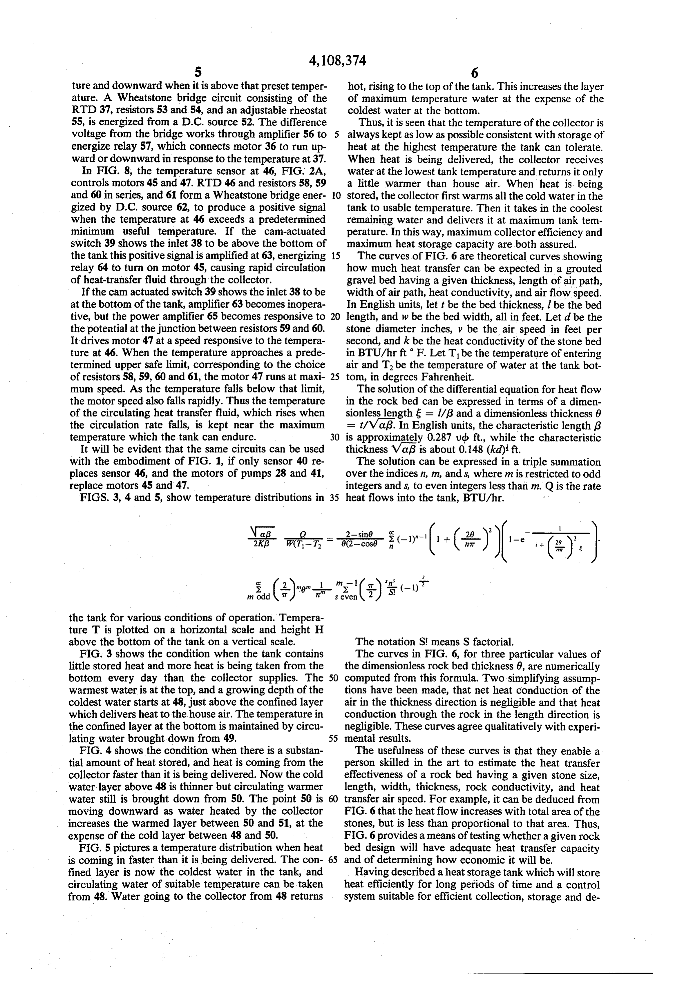
55, is energized from a D.C. source 52. The difference Thus, it is seen that the temperature of the collector is voltage from the bridge works through amplifier 56 to 5 always kept as low as possible consistent with storage of energize relay 57, which connects motor 36 to run up- heat at the highest temperature the tank can tolerate. ward or downward in response to the temperature at 37. When heat is being delivered, the collector receives In FIG. 8, the temperature sensor at 46, FIG. 2A, water at the lowest tank temperature and returns it only controls motors 45 and 47. RTD 46 and resistors 58,59 a little warmer than house air. When heat is being and 60 in series, and 61 form a Wheatstone bridge ener- 10 stored, the collector first warms all the cold water in the gized by D.C. source 62, to produce a positive signal tank to usable temperature. Then it takes in the coolest when the temperature at 46 exceeds a predetermined remaining water and delivers it at maximum tank tem minimum useful temperature. If the cam-actuated perature. In this way, maximum collector efficiency and switch 39 shows the inlet 38 to be above the bottom of maximum heat storage capacity are both assured. the tank this positive signal is amplified at 63, energizing 15 The curves of FIG. 6 are theoretical curves showing relay 64 to turn on motor 45, causing rapid circulation how much heat transfer can be expected in a grouted of heat-transfer fluid through the collector. gravel bed having a given thickness, length of air path, If the cam actuated switch 39 shows the inlet 38 to be width of air path, heat conductivity, and air flow speed. at the bottom of the tank, amplifier 63 becomes inopera- In English units, lett be the bed thickness, l be the bed tive, but the power amplifier 65 becomes responsive to 20 length, and w be the bed width, all in feet. Let d be the the potential at the junction between resistors 59 and 60. stone diameter inches, y be the air speed in feet per It drives motor 47 at a speed responsive to the tempera- second, and k be the heat conductivity of the stone bed ture at 46. When the temperature approaches a prede- in BTU/hr ft F. Let T be the temperature of entering termined upper safe limit, corresponding to the choice air and T be the temperature of water at the tank bot of resistors 58, 59, 60 and 61, the motor 47 runs at maxi- 25 tom, in degrees Fahrenheit.
mum speed. As the temperature falls below that limit, The solution of the differential equation for heat flow the motor speed also falls rapidly. Thus the temperature in the rock bed can be expressed in terms of a dimen of the circulating heat transfer fluid, which rises when sionless length & = l/g and a dimensionless thickness 6 the circulation rate falls, is kept near the maximum = t/Vag. In English units, the characteristic length 6 temperature which the tank can endure. 30 is approximately 0.287 ud ft., while the characteristic It will be evident that the same circuits can be used thickness Vag is about 0.148 (kd) ft. with the embodiment of FIG. 1, if only sensor 40 re- The solution can be expressed in a triple summation places sensor 46, and the motors of pumps 28 and 41, over the indices n, m, and s, where m is restricted to odd replace motors 45 and 47. integers and s, to even integers less than m. Q is the rate FIGS. 3, 4 and 5, show temperature distributions in 35 heat flows into the tank, BTU/hr.
the tank for various conditions of operation. Tempera ture T is plotted on a horizontal scale and height H above the bottom of the tank on a vertical scale. The notation S. means S factorial. FIG. 3 shows the condition when the tank contains The curves in FIG. 6, for three particular values of little stored heat and more heat is being taken from the the dimensionless rock bed thickness 6, are numerically bottom every day than the collector supplies. The 50 computed from this formula. Two simplifying assump warmest water is at the top, and a growing depth of the tions have been made, that net heat conduction of the coldest water starts at 48, just above the confined layer air in the thickness direction is negligible and that heat which delivers heat to the house air. The temperature in conduction through the rock in the length direction is the confined layer at the bottom is maintained by circu- negligible. These curves agree qualitatively with experi lating water brought down from 49. 55 mental results.
FIG. 4 shows the condition when there is a substan- The usefulness of these curves is that they enable a tial amount of heat stored, and heat is coming from the person skilled in the art to estimate the heat transfer collector faster than it is being delivered. Now the cold effectiveness of a rock bed having a given stone size, water layer above 48 is thinner but circulating warmer length, width, thickness, rock conductivity, and heat water still is brought down from 50. The point 50 is 60 transfer air speed. For example, it can be deduced from moving downward as water heated by the collector FIG. 6that the heat flow increases with total area of the increases the warmed layer between 50 and 51, at the stones, but is less than proportional to that area. Thus, expense of the cold layer between 48 and 50. FIG. 6 provides a means of testing whether a given rock FIG. 5 pictures a temperature distribution when heat bed design will have adequate heat transfer capacity is coming in faster than it is being delivered. The con- 65 and of determining how economic it will be. fined layer is now the coldest water in the tank, and Having described a heat storage tank which will store circulating water of suitable temperature can be taken heat efficiently for long periods of time and a control from 48. Water going to the collector from 48 returns system suitable for efficient collection, storage and de
Page 10
livery of solar heat energy, and having explained the 4. A heat storage tank suitable for solar house heating design sufficiently to be useful to those skilled in the art, systems according to claim 2, in which said control What we claim is the following: means controls the means for transferring heat from the 1. A heat storage tank suitable for solar house heating solar collector so that, systems having a solar heat collector, including: 5 water is circulated through said collector by said a rigidly supported bottom panel covered with a pump only when the temperature of said collector layer of stones of substantially uniform size which is above a minimum useful temperature, are bonded together thermally and mechanically at water for circulating to said collector is substantially their points of contact with each other, but which O when the coldest water in said tank, . have voids forming air passages remaining between the coldest water in said tank is below a useful them, bottom insulation below said bottom panel, a temperature, water is circulated to said collector at bottom air passage between said bottom insulation a maximum rate, and and said bottom panel, and at least one opening in when the coldest water in said tank is at least at useful said bottom panel whereby air can pass from said 15 temperature, water is circulated to said collector at bottom air passage into said layer of stones; a reduced rate, returning to said tank at the highest rigidly braced side panels having an inner layer of temperature permissable in said tank. outside insulation and an outer layer of outside systems 5. A heat storage tank suitable for solar house heating insulation and a continuous side air passage be means controls according to claim 3, in which said control tween them, communicating with the surface of 20 solar the means for transferring heat from a said layer of stones and a plenum chamber near the collector so that, top of said side panels, whereby air may pass from air is circulated through said collector by said blower said bottom air passage through said layer of only when the temperature of said collector is stones, through said side air passage to said plenum above a minimum useful temperature, when the coldest water in said tank is below a useful chamber; temperature, air is circulated to said collector at a a lining impervious to water having a bottom, sides 25 maximum rate, and and a top, top insulation mounted above said lining when the coldest water in said tank is at least at useful top; temperature, air is circulated to said collector at a means connected for transferring heat from a heat reduced rate, returning to said tank at the highest source to water contained in said tank, and heat 30 temperature permissable in said tank. delivery fluid means for delivery of heat from said 6. A heat storage tank suitable for solar house heating tank; systems, including:
means for circulating water from a controllable a rigidly supported bottom panel, height within said tank to the inside bottom surface a heat exchanger mounted under said bottom panel, of said tank, and means for constraining said circu 35 a bottom air passage connected to said heat ex lating water to flow over the inside bottom surface changer, of said tank, whereby the temperature of said tank rigidly braced side panels connected to said bottom inside bottom surface is kept substantially equal to panel having an inner layer of outside insulation the temperature of water at said controllable and an outer layer of outside insulation, a continu height; and ous side air passage between them, a plenum cham control means responsive to the temperature of said ber near the top of said side panels communicating heat delivery fluid for adjusting said controllable with said air passage whereby air may pass from height, and for adjusting the rate of said means for said bottom air passage through said heat ex transferring heat from the solar heat collector re changer, through said side air passage to said ple sponsive to said controllable height and to the 45 num chamber;
temperature at said solar collector. means connected for transferring heat from a heat 2. A heat storage tank suitable for solar house heating source to water contained in said tank, and heat systems according to claim 1, in which said means for deliver fluid means for delivery of heat from said transferring heat from the solar collector includes a tank, piping system and a pump for drawing water from near 50 means connected to said tank for circulating water the bottom of said tank, circulating it through said col from a controllable height within said tank to the lector and returning it near the bottom of said tank. inside bottom surface of said tank, and means in 3. A heat storage tank suitable for solar house heating said tank for constraining said circulating water to systems according to claim 1, in which said means for flow over the inside bottom surface of said tank, transferring heat from a solar collector includes a duct 55 whereby the temperature of said tank inside bottom system and a blower for drawing air from said plenum, surface is kept substantially equal to the tempera circulating it through said solar heat collector and re ture of water at said controllable height. turning it to said bottom air passage.
Provenance
- Collection
- Cited prior art
- Original PDF
- patentimages.storage.googleapis.com →
- Filed
- 1976-07-29
- Pages
- 10
- Method
- pdftotext (the PDF's own text layer) + pdftoppm 300dpi page scans
- Source
- Google Patents bibliographic record
- Granted
- 1978-08-22
- Inventors
- Floyd A. Lyon; Henry Harrison; Halm Instrument Co Inc
- Transcribed from
- patentimages.storage.googleapis.com →