patent · US4077849
Desalination apparatus
7 March 1978
Page 1 — bibliographic record
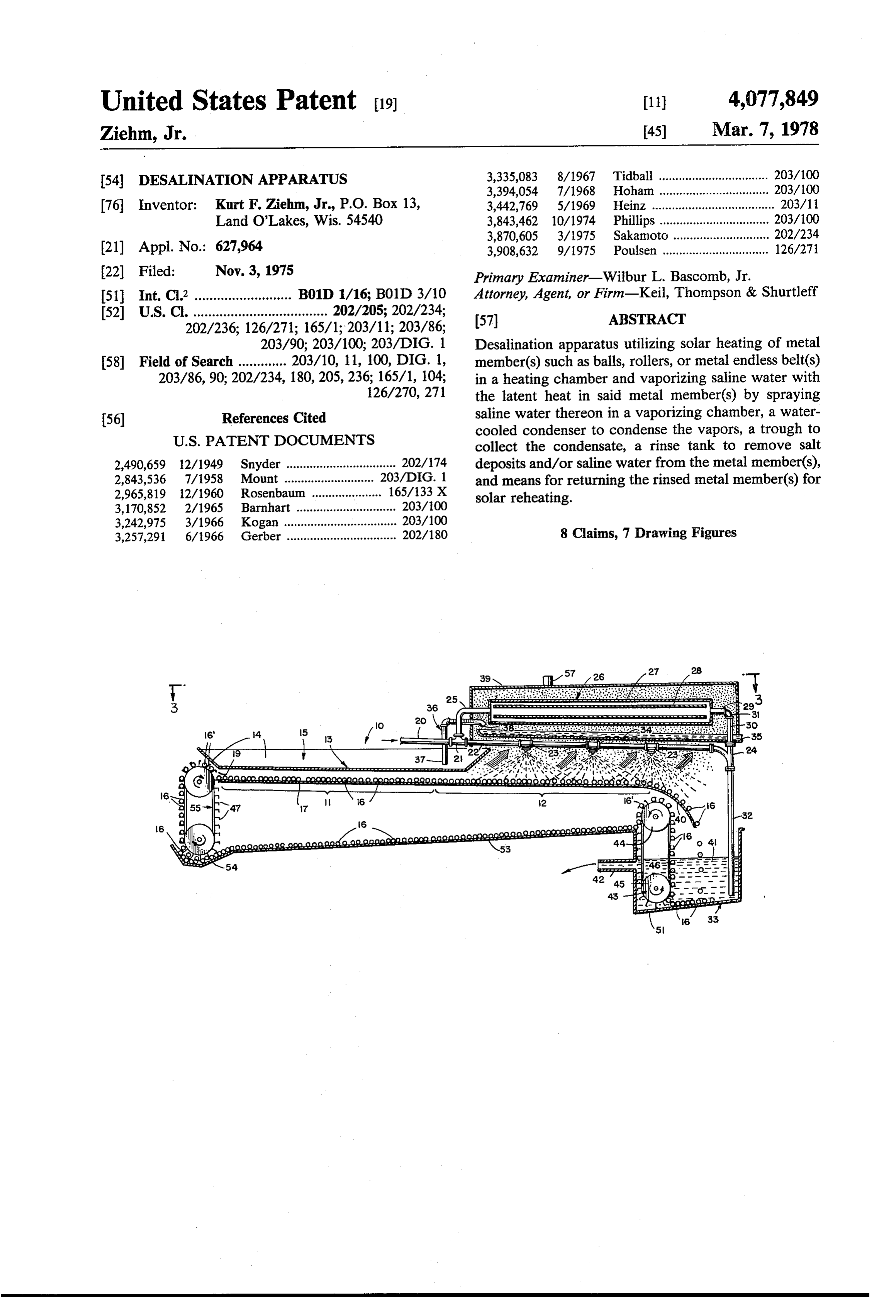
United States Patent (19) 11) 4,077,849 Ziehm, Jr. 45) Mar. 7, 1978 54). DESALINATION APPARATUS 3,335,083 8/1967 Tidball ................................. 203/100 3,394,054 7/1968 Hoham ................................. 203/100 76 Inventor: Kurt F. Ziehm, Jr., P.O. Box 13, 3,442,769 5/1969 Heinz ..................................... 203/11 Land O'Lakes, Wis. 54540 3,843,462 10/1974 Phillips ................................. 203/100 3,870,605 3/1975 Sakamoto ............................. 202/234 (21) Appl. No.: 627,964 3,908,632 9/1975 Poulsen ................................ 126/271 22 Filed: Nov. 3, 1975 Primary Examiner-Wilbur L. Bascomb, Jr. 51 Int. C.? .......................... B01D 1/16; B01D 3/10 Attorney, Agent, or Firm-Keil, Thompson & Shurtleff 52 U.S. Cl. .................................... 202/205; 202/234; (57) ABSTRACT
203/90; 203/100; 203/DIG. 1 Desalination apparatus utilizing solar heating of metal 58 Field of Search ............. 203/10, 11, 100, DIG. 1, member(s) such as balls, rollers, or metal endless belt(s) 203/86, 90; 202/234, 180, 205, 236; 165/1, 104; in a heating chamber and vaporizing saline water with 126/270, 271 the latent heat in said metal member(s) by spraying 56) References Cited saline water thereon in a vaporizing chamber, a water
cooled condenser to condense the vapors, a trough to collect the condensate, a rinse tank to remove salt 2,490,659 12/1949 Snyder ................................. 202/174 deposits and/or saline water from the metal member(s), 2,843,536 7/1958 Mount ......... ... 203/DIG. 1 and means for returning the rinsed metal member(s) for 2,965,819 12/1960 Rosenbaum ..................... 165/33 X solar reheating.
3,170,852 2/1965 Barnhart .............................. 203/100 3,242,975 3/1966 Kogan .................................. 203/100 3,257,291 6/1966 Gerber ................................. 202/180 8 Claims, 7 Drawing Figures
Page 2
Drawing sheet — no readable text.
Page 3
Drawing sheet — no readable text.
Page 4
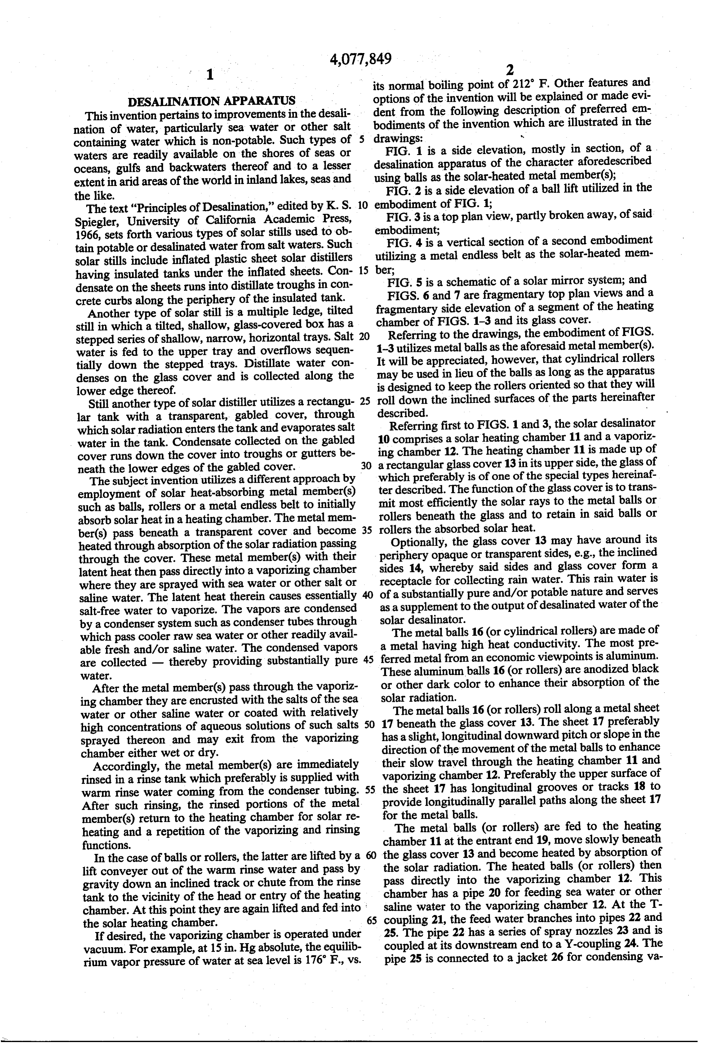
its normal boiling point of 212 F. Other features and
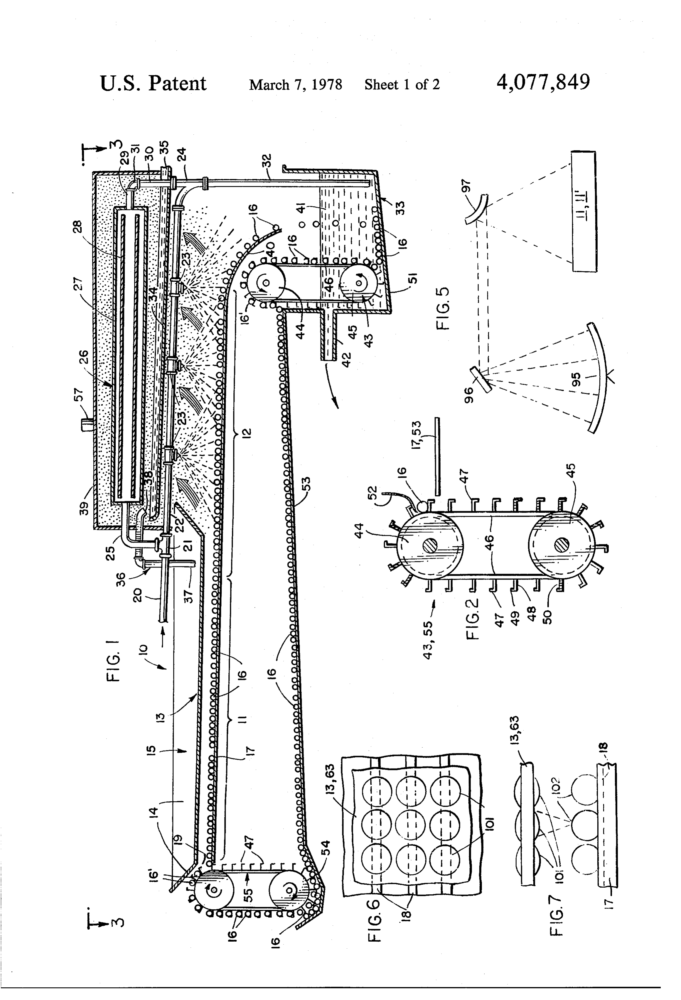
DESALNATION APPARATUS options of the invention will be explained or made evi This invention pertains to improvements in the desali dent from the following description of preferred em nation of water, particularly sea water or other salt bodiments of the invention which are illustrated in the containing water which is non-potable. Such types of 5 drawings: V waters are readily available on the shores of seas or FIG. 1 is a side elevation, mostly in section, of a oceans, gulfs and backwaters thereof and to a lesser desalination apparatus of the character aforedescribed extent in arid areas of the world in inland lakes, seas and using balls as the solar-heated metal member(s); FIG. 2 is a side elevation of a ball lift utilized in the the like.
The text "Principles of Desalination,” edited by K. S. 10 embodiment of FIG. 1;
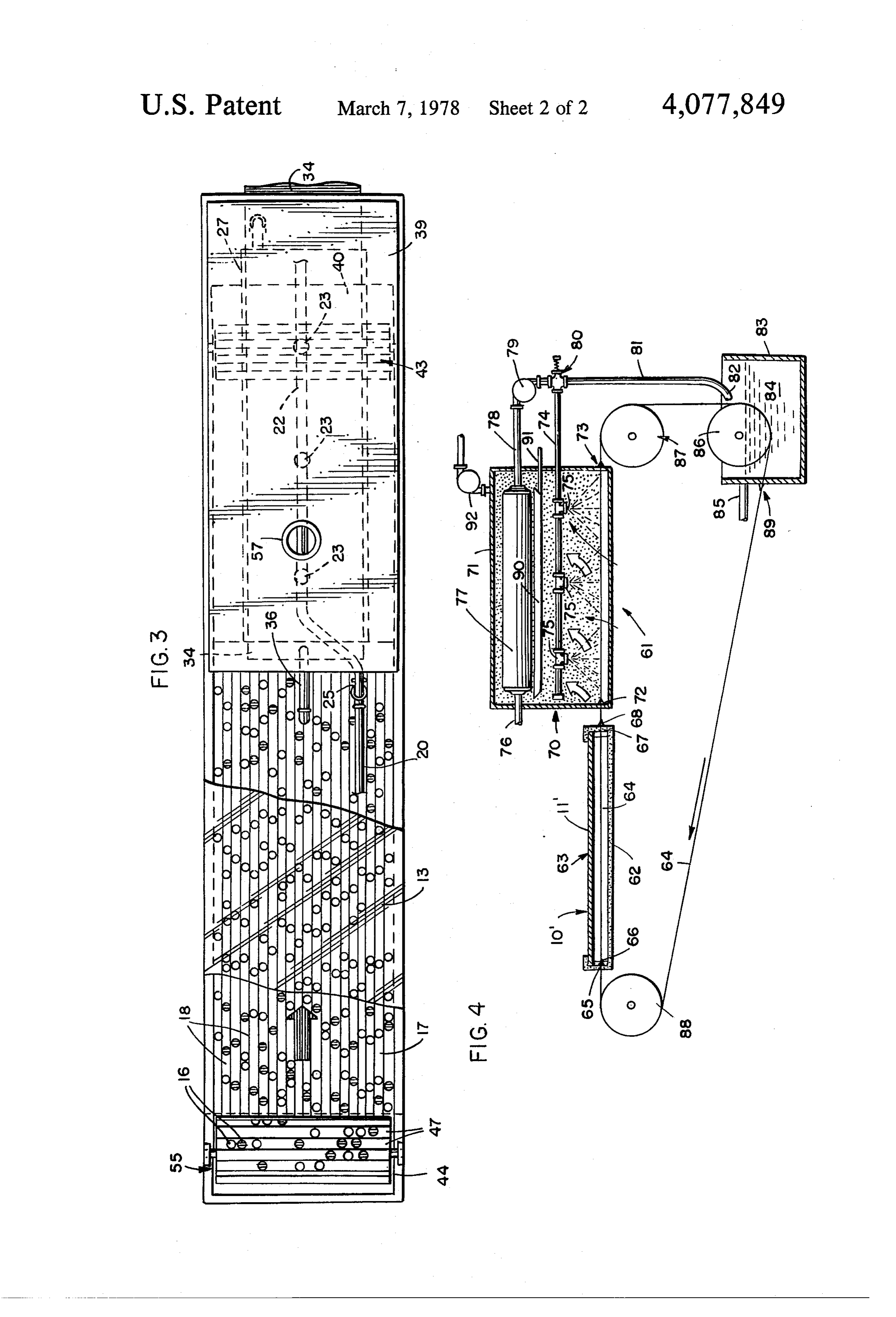
FIG. 3 is a top plan view, partly broken away, of said
Spiegler, University of California Academic Press, 1966, sets forth various types of solar stills used to ob embodiment;
FIG. 4 is a vertical section of a second embodiment tain potable or desalinated water from salt waters. Such utilizing a metal endless belt as the solar-heated mem solar stills include inflated plastic sheet solar distillers 15 having insulated tanks under the inflated sheets. Con ber;
densate on the sheets runs into distillate troughs in con FIG. 5 is a schematic of a solar mirror system; and crete curbs along the periphery of the insulated tank. FIGS. 6 and 7 are fragmentary top plan views and a Another type of solar still is a multiple ledge, tilted fragmentary side elevation of a segment of the heating still in which a tilted, shallow, glass-covered box has a chamber of FIGS. 1-3 and its glass cover. stepped series of shallow, narrow, horizontal trays. Salt 20 Referring to the drawings, the embodiment of FIGS. water is fed to the upper tray and overflows sequen 1-3 utilizes metal balls as the aforesaid metal member(s). tially down the stepped trays. Distillate water con It will be appreciated, however, that cylindrical rollers denses on the glass cover and is collected along the may be used in lieu of the balls as long as the apparatus is designed to keep the rollers oriented so that they will lower edge thereof.
Still another type of solar distiller utilizes a rectangu 25 roll down the inclined surfaces of the parts hereinafter lar tank with a transparent, gabled cover, through described.
which solar radiation enters the tank and evaporates salt 10Referring first to FIGS. 1 and 3, the solar desalinator comprises a solar heating chamber 11 and a vaporiz water in the tank. Condensate collected on the gabled cover runs down the cover into troughs or gutters be ing chamber 12. The heating chamber 11 is made up of neath the lower edges of the gabled cover. 30 a rectangular glass cover 13 in its upper side, the glass of which preferably is of one of the special types hereinaf
The subject invention utilizes a different approach by employment of solar heat-absorbing metal member(s) ter described. The function of the glass cover is to trans such as balls, rollers or a metal endless belt to initially mit most efficiently the solar rays to the metal balls or absorb solar heatin a heating chamber. The metal mem rollers rollers beneath the glass and to retain in said balls or the absorbed solar heat.
ber(s) pass beneath a transparent cover and become 35
Optionally, the glass cover 13 may have around its heated through absorption of the solar radiation passing periphery opaque or transparent sides, e.g., the inclined through the cover. These metal member(s) with their latent heat then pass directly into a vaporizing chamber sides 14, whereby said sides and glass cover form a where they are sprayed with sea water or other salt or receptacle for collecting rain water. This rain water is of a substantially pure and/or potable nature and serves saline water. The latent heat therein causes essentially as a supplement to the output of desalinated water of the salt-free water to vaporize. The vapors are condensed by a condenser system such as condenser tubes through solar desalinator.
which pass cooler raw sea water or other readily avail a metal The metal balls 16 (or cylindrical rollers) are made of able fresh and/or saline water. The condensed vapors 45 ferred having high heat conductivity. The most pre are collected - thereby providing substantially pure metal from an economic viewpoints is aluminum. Water. These aluminum balls 16 (or rollers) are anodized black After the metal member(s) pass through the vaporiz or other dark color to enhance their absorption of the ing chamber they are encrusted with the salts of the sea solar radiation.
water or other saline water or coated with relatively 17The metal balls 16 (or rollers) roll along a metal sheet beneath the glass cover 13. The sheet 17 preferably high concentrations of aqueous solutions of such salts 50 has a slight, longitudinal downward pitch or slope in the sprayed thereon and may exit from the vaporizing chamber either wet or dry. direction of the movement of the metal balls to enhance Accordingly, the metal member(s) are immediately their slow travel through the heating chamber 11 and rinsed in a rinse tank which preferably is supplied with vaporizing chamber 12. Preferably the upper surface of warm rinse water coming from the condenser tubing. 55 provide the sheet 17 has longitudinal grooves or tracks 18 to After such rinsing, the rinsed portions of the metal longitudinally parallel paths along the sheet 17 member(s) return to the heating chamber for solar re for the metal balls.
heating and a repetition of the vaporizing and rinsing The metal balls (or rollers) are fed to the heating functions. chamber 11 at the entrant end 19, move slowly beneath In the case of balls or rollers, the latter are lifted by a 60 the glass cover 13 and become heated by absorption of lift conveyer out of the warm rinse water and pass by pass the solar radiation. The heated balls (or rollers) then gravity down an inclined track or chute from the rinse directly into the vaporizing chamber 12. This tank to the vicinity of the head or entry of the heating chamber has a pipe 20 for feeding sea water or other chamber. At this point they are again lifted and fed into saline water to the vaporizing chamber 12. At the T the solar heating chamber. 65 coupling 21, the feed water branches into pipes 22 and If desired, the vaporizing chamber is operated under 25. The pipe 22 has a series of spray nozzles 23 and is vacuum. For example, at 15 in. Hg absolute, the equilib coupled at its downstream end to a Y-coupling 24. The rium vapor pressure of water at sea level is 176' F., vs. pipe 25 is connected to a jacket 26 for condensing va
Page 5
pors, the feed water keeping the jacket cool for conden and lip forms an elongated seat 50 for conveyance of the sation thereon. The jacket 26 may comprise a shell 27 balls 16 (or rollers).
containing internal baffling or tubing 28 over or As shown in FIG. 1, the rinse tank 33 has a bottom through which the cooling water flows inside the wall 51 which is downwardly pitched in the direction jacket. Alternatively, the condenser may simply be a toward the lift 43 extending along one edge of the rinse series of convoluted or parallel tubes without an exter tank. As the ball lift operates within the tank, the rinsed nal jacket. balls 16 (or rollers) are picked up at the bottom of the The downstream end of the jacket 26 is connected by tank At 33 and lifted upwardly in the seats 50.
the upper side of the roller or pulley 44, the balls pipes 29 and 30 and their intermediary elbow 31 with the Y-coupling 24. In passing through the jacket 26 and 10 (or rollers) fall out of the seats 50, e.g., the balls 16'. A the pipe 22, the sea water or other salty or saline water resilient lifts 47.
blade 52 (FIG. 2) projects into the path of the
The balls 16 are pushed by the free edge of the is warmed by heat exchange occurring within the va blade 52 off the back side of the lifts onto the sheet 17 or porizing chamber 12. This warmed water is fed by pipe 53 when the following lift 47 strikes the blade 52. 32 to a rinse tank 33, described below.
When the sea water or the like is sprayed from noz 15 theThe head ball return from the lift 43 of the rinse tank 33 to or entrant end 19 of the solar heating chamber zles 23 onto the heated balls (or rollers) passing through 11 comprises the vaporizing chamber 12, all or a substantial portion sheet 53. Thea sloping or pitched, ball (or roller) return of the sprayed water is vaporized. The vapors rise as rinse tank and its lift to a slopes sheet 53 downwardly from the collector well 54. The balls 16 indicated by the arrows in FIG. 1 into the upper portion of the vaporizing chamber. Here the vapors are con 20 (or rollers) accumulated in the well are picked up by the lifts 47 of the lift 55, the structure of which is illustrated densed on the cooler shell 27 and the condensate drops into a condensate-collecting trough 34 beneath the in FIG. 2. The balls or rollers are then lifted and dis charged onto the sheet 17 at its entrant end 19 for an jacket 26. The condensate trough has a slight pitch so other cycle that the substantially pure condensate water 35 flows by 25 If desired,asthe aforedescribed. vaporizing chamber 12 may be oper gravity out of the vaporizing chamber 12. ated under partial vacuum. For this purpose, a vacuum Where the heating chamber 11 embodies a rain-water tap 57 is provided in the top wall of the housing 39. A collecting receptacle 15, a tap pipe 36 may be used to partial vacuum has the advantage of lowering the va convey the collected rain water from the pipe's lower porizing temperature of the water sprayed onto the end 37 adjacent the glass cover 13 to its discharge end 30 heated balls (or rollers) in the vaporizing chamber. 38 at the head end of the condensate-collecting trough Another embodiment of desalination apparatus 10' is 34. A mechanical or water pump (not shown) may be illustrated in FIG. 4. In many respects this embodiment provided on or in the tap pipe 36. is like the embodiment of FIGS. 1-3. Here, however, The upper portion of the vaporizing chamber is an the metal member, which is solar heated, is an endless enclosed housing 39 which is sealed against loss of 35 metal band or belt. Referring to FIG. 4, the solar desali vapor contained within the housing. The lower end of nator 61 comprises an insulated heating chamber 62 the housing 39 may be open, as illustrated, or it may having a glass cover 63. An endless belt 64 (or a series have depending walls, gaskets, etc. to prevent escape of of side-by-side endless belts) is made of flexible, heat vapors substantially in the manner described below conducting metal. Again aluminum is particularly suit with reference to FIG. 4. The condensate-collecting 40 able, particularly thin-rolled aluminum which is anod trough 34 has a width less than the width of the housing ized black or other dark, heat-absorptive color. 39 so that vapors can pass upwardly around the trough The endless belt(s) 64 enters the solar heating cham into the upper portion of the housing 39. ber 62 through a horizontal slit 65. In passing through The discharge end 40 of the ball-conveying plate 17 the heating chamber, it absorbs solar radiation and be has a downward pitch or curvature above the rinse tank 45 comes heated. Preferably, the slit has a rubber seal or 33. The balls (or rollers) fall into the warm sea, salt or wiper 66 extending along its length. The endless belt(s) saline water 41 in the rinse tank, the water level being exits from the heating chamber 62 through another maintained constant at the level of the overflow pipe 42, horizontal slit 67 also having a rubber seal or wiper 68. from which the discharge water is returned to the sea, The heated belt(s) immediately enter the vaporizing ocean, lake, etc. 50 chamber 70. This chamber comprises a six-sided enclo The balls 16 (or rollers) have, after passing through sure 71, the heated belt(s) entering the chamber 70 the vaporizing chamber 12, solid salt deposits or con through the horizontal slot 72 with a wiper or seal as centrated salt solutions on their surfaces. The salt de aforesaid. The belt(s) exits from the opposite side of the posits and/or concentrated salt solutions are rinsed off enclosure 71 through a similar horizontal slit 73 with a in the warm water 41 in the tank 33. The balls 16 (or 55 rubber wiper or seal as aforesaid. rollers) are then conveyed by a lift 43 from the bottom Sea water or other salty or saline water is fed to the of the tank for return to the heating chamber 11. The lift horizontal pipe 74 bearing axially spaced spray nozzles 43 and another lift 55, the function of which is later 75. The water is sprayed onto the heated belt(s), causing described, have the construction illustrated in FIG. 2. the water to vaporize in the enclosure 71.
These lifts comprise an upper roller or pulley 44 and a 60 The sea, salty or saline water is supplied through the lower roller or pulley 45, one of which is driven. An feed pipe 76. This water is relatively cool, e.g., at ambi endless belt or series of side-by-side belts 46 is posi ent temperature, and first flows through the condenser tioned about and driven by the rollers or pulleys 4445, jacket and/or tubing 77, exiting from the opposite end which rotate in the direction of the arrows shown in via the pipe 78. At this stage, the water has a rise in FIG. 1. A series of longitudinally elongated lifts 47 are 65 temperature. A pump 79 may be provided at any point, mounted on the belt(s) 46. Each lift comprises an elon e.g., at a point immediately before the pressure relief gated bar 48 connected at one edge to the belt(s) 46 and valve 80, which also serves as the tap off coupling for bearing an elongated lip 49 at the other edge. Each bar the pipes 74 and 81.
Page 6
The pipe 81 extends downwardly from the pressure respective balls as they pass through the heating cham relief valve toward the belt(s) rinse tank 83. Its dis ber.It is believed that the advantages and objectives of charge end 82 may be in the form of a spray nozzle which directs spray directly against the belt(s) above the invention will be appreciated from the foregoing description of the generic invention and its preferred the level of the rinse water 84 in the tank 83 to aid in loosening salt deposits which may have formed on the tion embodiments. Other embodiments of the generic inven belt(s) in the vaporizing chamber 70. may be realized without departing from the scope of the
The belt(s) is immersed in the rinse water 84, which is dependent invention described aforesaid and set forth in the heated or warned sea, salt or saline water, the level of claims.
I claim:
which is maintained constant by the overflow pipe 85, 10 1. Solar desalination apparatus comprising a heating from which the water is returned to its original source. chamber
The belt(s) 64 travels over three drums or rollers 86, upper side,having a a light-permeable, glass cover in its plurality of small, solar-heatable, metal 87 and 88, one of which is driven. If the belt(s) exits balls, parallel tracks extending longitudinally through from the rinse tank 63 below the level of the rinse water said chamber beneath said cover 84, this is conveniently done through a horizontal slit in 15 through said chamber, said glass coverto convey said balls the side wall of the tank 83, which slit is maintained of rows of lenses, said rows being directly being composed relatively watertight by the rubber seal 89. The latter aligned with said tracks, said lenses focusingabove solar and rays also serves as a wiper to remove all or most of the rinse at approximately the uppermost level of said balls as water from the exiting belt(s).
As in the embodiment of FIGS. 1-3, the vaporizing 20 they roll along said tracks through said chamber to subject said balls to solar radiation and thereby heat said chamber has a condensate-collector pan or trough 90 balls, a vaporizing chamber adjacent said heating cham below the condenser 77 to collect condensed, essen ber, means to convey the heated balls through said tially salt-free condensate formed on the cooled surfaces vaporizing chamber, means for applying saline water of the condenser. This water is withdrawn through the onto said heated balls in said vaporizing chamber to tap offpipe 91. The enclosure 71 may be operated under 25 vaporize the water applied thereon, and condensing partial vacuum, e.g., by providing a vacuum pump 92 means to condense the essentially salt-free water vapors and appropriate piping on the upper wall of the enclo so produced.
Sure 71. 2. A desalination apparatus as claimed in claim 1, a The glass covers 13 and 63 preferably are made of rinse special glass which maximizes transmission of both 30 meanstank, means for supplying rinse water to said tank, to feed said balls from said vaporizing chamber direct and diffuse sunlight and the heating of the metal into the rinse water in said tank, and further means to member(s) therebeneath. An exemplary, suitable glass is convey the rinsed metal balls back to said heating cham "solarpane' glass marketed by Pittsburgh Plate Glass. ber.
Another type of special glass with lenses is described 3. Solar desalination apparatus as claimed in claim 2 below. wherein said condensing means comprises means for In FIG. 5, a solar mirror system is illustrated dia 35 circulation of saline water through the condenser gramatically, which system is useful in maximizing means, whereby said saline water becomes warmer as it transmission of solar radiation to the heating chamber passes through said condensing means, and pipe means 11 throughout the sunlight hours. A pivotable parabolic to feed the warmer saline water from said condensing mirror 95 is pivoted to follow the path of the sun from means to said rinse tank whereby said warmer saline 1 or 2 hours after dawn to 1 or 2 hours before dusk. The 40 water serves as the supplied rinse water. reflected rays from the mirror 95 are reflected by the 4. Solar desalination apparatus as claimed in claim 1 planar mirror 96, which in turn is movable and/or wherein said heatable balls comprise aluminum balls fed pivotable to maintain its proper orientation with the by ball-conveying means to entrant part of said heating pivotable parabolic mirror. chamber.
The mirror 96 is maintained at the approximate focus 45 5. Solar desalination apparatus as claimed in claim 1 point of the mirror 95 and reflects the solar rays later wherein said metal balls are aluminum balls anodized in ally to a spherical or cylindrical convexo-concave sta a dark, heat-absorbing color.
tionary mirror 97. The latter is positioned directly 6. A desalination apparatus as claimed in claim 1, and above the solar heating chamber 11 or 11’ and reflects a rinse tank, means for supplying rinse water to said the solar rays downwardly over substantially the whole 50 tank, means to feed large number of said heatable balls light transmitting portion of the heating chamber 11 or from said vaporizing chamber into the rinse water in 11'. Such mirror arrangement allows the subject solar said tank, and further means to convey the rinsed metal desalination apparatus to be used during most of the day balls back to said heating chamber, said last mentioned light hours. means embodying an endless belt lift member to raise FIGS. 6 and 7 constitute a top plan view and a side 55 said heatable balls out of the rinse water in said rinse elevation of a segment of the heating chamber 11 or 11'. tank, and additional means for conveying the so-lifted The glass cover 13,63 is composed of rows of lenses 101, heatable balls from said endless belt lift member to the such rows being directly above and aligned with the entrant portion of said heating chamber. tracks or grooves 18 in the sheet 17. These lenses focus 7. Solar desalination apparatus as claimed in claim 6 the solar rays at approximately the uppermost level 102 60 wherein said additional means comprises an inclined of the balls 16 (or at the plane of the endless metal belt sheet for conveying said balls by gravity from said lift to 63 in the heating chamber 11), this maximizing the a well directly below the entrant portion of said heating concentration of solar heat in a manner similar to the chamber, and a second endless ball lift for conveying focusing of a magnifying glass upon combustible mate said balls from said well to said entrant portion of said rial to ignite same. In a case of the heating of metal balls, heating chamber.
the respective lenses 101 maximizes the application of 65 8. Solar desalination apparatus as claimed in claim 1, solar radiation by positioning of their focal point di and means for creating a partial vacuum in said vaporiz rectly above the tracks or grooves 18 whereby the solar ing chamber. k k is radiation is applied along the rolling diameters of the
Provenance
- Collection
- Cited prior art
- Original PDF
- patentimages.storage.googleapis.com →
- Filed
- 1975-11-03
- Pages
- 6
- Method
- pdftotext (the PDF's own text layer) + pdftoppm 300dpi page scans
- Source
- Google Patents bibliographic record
- Granted
- 1978-03-07
- Inventors
- Kurt F. Ziehm, Jr.
- Transcribed from
- patentimages.storage.googleapis.com →