patent · US3936157
High efficiency light transmitting window panel
3 February 1976
Page 1 — bibliographic record
United States Patent 1191 1111 3,936,157 Kapany [451- Feb. 3, 1976
[54} HIGH EFFICIENCY LIGHT TRANSMITTING FOREIGN PATENTS OR APPLICATIONS
WINDOW PANEL
404,303 11/1909 France .............................. .. 352/258 [75] Inventor: Narinder S. Kapany, Woodside,
Cahf- Primary Examiner—Monroe H. Hayes [73} Assignee: Knptron, Inc., Palo Alto, Calif. gftomey, Agent, or Firm-Limbach, Limbach & utton
[21] Appl. No.: 462,856 [57] ABSTRACT _ The window panel includes a plurality of sets of re [52] U.S. Cl. .............................................. .. 350/258 ?eeting surfaces which are-spaced apart from and fac [51] Int. Cl.2 ........................................ .. G02B 17/00 ing each other and which transmit the incident light at [58] Field 0! Search ......... .. 350/258, 259, 260, 261, least in part by multiple re?ections. The sets of re 350/262, 263, 264, 265 ?eeting surfaces are arranged parallel to each other in a panel. In at least one embodiment the sets of op [56] , References Cited posed re?ecting surfaces converge in the direction of UN‘TED STATES PATENTS incident light travel through the window panel and in . frared reflecting means are provided to re?ect infra
9821,72 mzggslf?hm ; red light attemptmg to pass through the wmdow panel 2327518 8/1943 Miner ________ n 350/263 ' in a direction opposite to the direction of travel of the 2,506.951 5/1950 Doane ...... .. 350/259 x incident light 2.828.235 3/1958 Holland 350/258 X - 3,537,944 11/1910 Grubb ........................... .. 350/259 x 10 Claims’ 13 Drawing “guns
/ * I " - l l - * ea- '~
20 "1 Q {(11:81 | \ 3
— t I I I 1 l l \ ~
EXTERIOR , 1;: 1101' i 11 d 1.95: 49h \~
12 ~T~ 1 -~ ,- ~~
Page 2
SOLAR ENERGY
EXTERIOR
t\\\‘\\\\*/.>\§\‘/\\\/266\\‘. \>\>\\\\*?I L\\\\‘~\\ y»; “an :ex ?, 7 {A Z / 28 ¢ / 30/; ,g 4
is‘ \\\x\ \\\\\\\\\\\7 QNNDRNNNXSNNXN‘NNNW
28 AIR
sm 9=(n2—l)y2 ' (n2 - “3)
l 3A LIGHT IS TOTALLY n —:_ §/ REFLECTED INTER
Page 3
Drawing sheet — no readable text.
Page 4
Drawing sheet — no readable text.
Page 5
from and face each other, either directly or obliquely,
HIGH EFFICIENCY LIGHT TRANSMITTING so that multiple re?ections can occur. In some pre WINDOW PANEL ferred embodiments of the invention, the plurality of opposed re?ecting surfaces converge in the overall
CROSS-REFERENCE TO RELATED APPLICATION direction of the incident light travel through the win The present application is related in part to the appli dow. In one such embodiment, for example, the op cant‘s co-pending application, Ser. No. 462,870, ?led posed re?ecting surfaces are arranged in V-shaped, Apr. 22, I974 and entitled "HIGH EFFICIENCY parallel grooves.
SOLAR PANEL”. In some preferred embodiments means are also pro vided to re?ect infrared light striking the panel. In one
BACKGROUND OF THE INVENTION type of embodiment the infrared light striking the panel The invention relates to a window panel and more from a direction opposite to that of the incident light is particularly to a high efficiency light transmitting win re?ected. For example, in one such embodiment of this dow panel for passing incident solar light into a room type a plurality of parallel, triangularly shaped wedges while simultaneously blocking the escape of heat en~ are provided for supporting the opposed re?ecting ergy by radiation, convection or conduction from the surfaces. Each wedge has one apex pointing generally room. toward the source of incident light and supports a pair In the design of buildings, it is desirable that the of re?ecting surfaces which diverge from the one apex windows efficiently pass solar radiation while blocking in the direction of incident light travel through the the escape of heat from the inside of the building by 20 window. Thus, in effect, the set of re?ecting surfaces either radiation, conduction or convection. Further supported by each pair of adjacent wedges which face more, it is desirable that such solar radiation be trans each other converge in the direction of light travel mitted through the window over as wide a range of through the window. The means for re?ecting the infra incident angles as possible. red radiation comprise infrared re?ecting surfaces In some prior art windows one or more panes of which are disposed between the other two apexes of transparent glass or plastic are separated by air. Such each wedge, that is, the infrared re?ecting surfaces are double pane windows are somewhat effective in block arranged so as to face the interior of the building struc ing the escape of heat by means of conduction since the ture in which the window is mounted and are supported air chamber between the panes acts as a barrier to adjacent to the ?at surface of the bottom of each direct conductive heat loss. However, convective air wedge.
currents within the air chamber are generated by the The window in other embodiments of the invention temperature differential between the panes and this comprises a pair of thin, transparent sheets which are causes a significant heat loss. Also heat generated or separated by a plurality of ribs made of light transmit reemitted (in the form of infrared light, for example) ting material arranged to transmit the incident light from within the building passes easily through the win 35 striking the ribbed portion of the window within a pre dow, causing further heat loss. Still another problem of determined angle of acceptance by means of multiple, such double pane windows is that much of the light is total internal re?ections. In one embodiment, for ex lost which strikes the window at large incident angles ample, the ribs take the form of a plurality of transpar (measured with respect to the normal to the outer ent columns while in other embodiments the ribs are in pane.) Thus, the closer the incident light comes to the form of transparent zig-zag walls. In these embodi being tangential to the window, the less efficient the ments the window portion preferably further includes window becomes in transmitting the incident light. means for segmenting air spaces between the sheets to The light transmitting characteristics of the ideal reduce convection heat losses and to better distribute window should be independent of the angle of inci the mechanical load applied to the window. denee or polarization, thus making the window useful 45 In still other embodiments, the “ribs” are in the form even on a cloudy day. The window should also be made of light transmitting honeycomb cells which also seg of low cost materials without sacri?cing sturdiness. ment the air space between the sheets. These forms of Some of these requirements are contradictory. For construction have the advantages of light weight, stur example, in order to make the window sturdy or in diness, high light transmission and relatively low cost. order to make it more effective in blocking the escape 50 Many of the above described features of the inven of heat energy, some lower light transmitting qualities tion may be utilized independently of some of the oth than relatively thinner windows. Thus, the light trans ers, but they are preferably combined into a window mitting capability is degraded to improve the capability which is highly efficient in transmitting incident solar to block the escape of heat energy. Furthermore, when radiation while simultaneously blocking the escape of the window is made relatively thick the light accep 55 heat.
tance angle properties may be degraded in some prior It is, therefore, an object of the present invention to art arrangements. provide a window which is highly efficient in transmit ting light over a wide range of incident angles;
SUMMARY OF THE INVENTION It is another object of the invention to provide a The above described disadvantages of the prior art 60 window which has high light transmissive qualities are overcome and the requirements for a highly effi while simultaneously being an effective barrier to the cient incident light transmitting window panel are met escape of heat energy;
by the present invention comprising a plurality of paral It is a further object of the invention to provide a high lel sets of opposed re?ecting surfaces arranged in a efficiency window panel wherein the panel is low cost, panel which transmit the incident light through the 65 lightweight and sturdy; and panel at least in part by multiple re?ections. By “0p It is a still further objec of the invention to provide a posed re?ecting surfaces" is meant that separate ones high efficiency window panel which has low heat losses of the plurality of re?ective surfaces are spaced apart due to radiation, convection and conduction.
Page 6
The foregoing and other objectives, features and as plastic and pressed against the ?at panels to reduce advantages of the invention will be more readily under re?ection losses at curved surfaces. stood upon consideration of the following detailed Referring now more particularly to FIGS. 20 and 2b, description of certain preferred mbodiments of the other types of columns and air space segmenting are invention, taken in conjunction with the accompanying depicted. In the embodiment of FIG. 2a the window drawings. sheets 20 and 22 are separated by a plurality of thin sheets 28 turned on edge to form a plurality of parellel
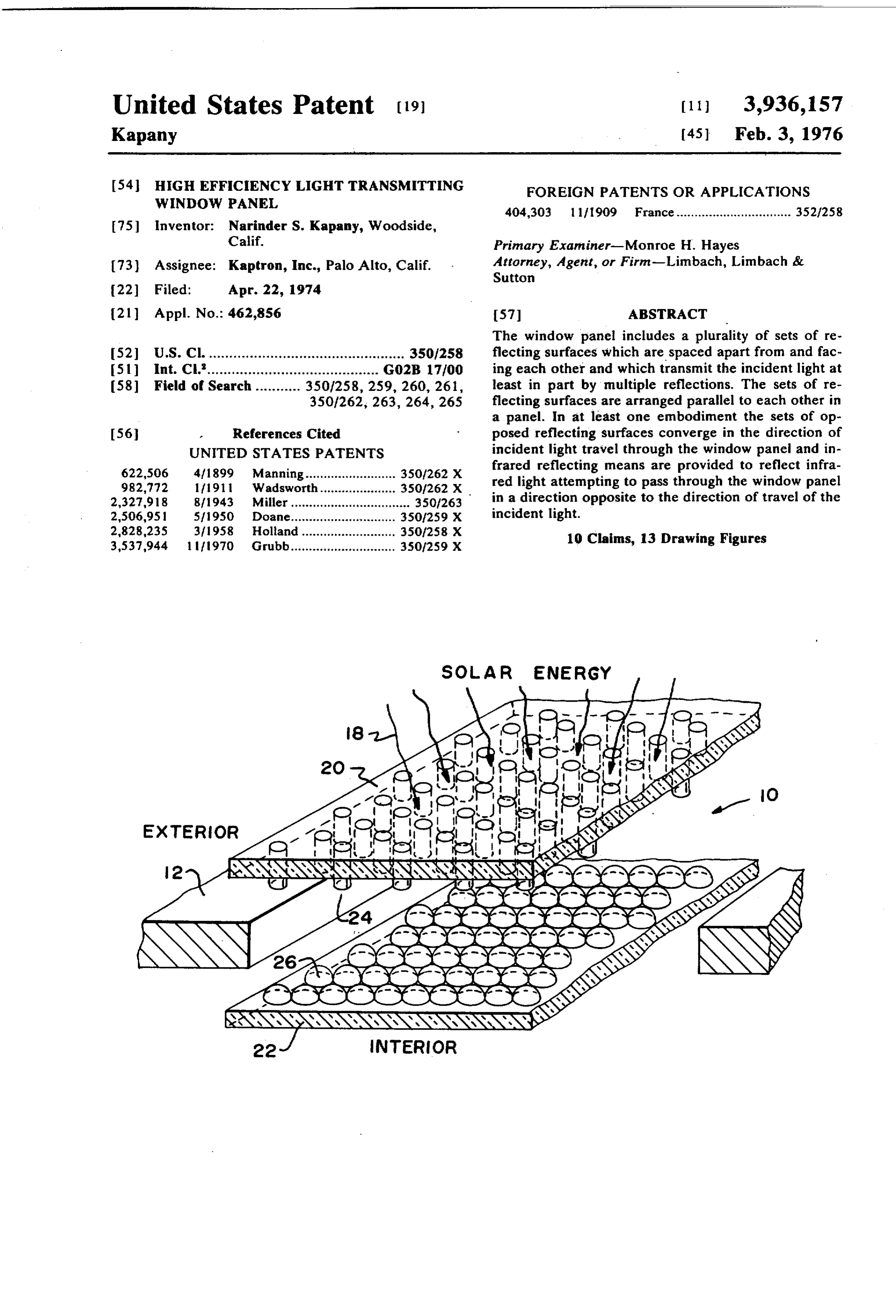
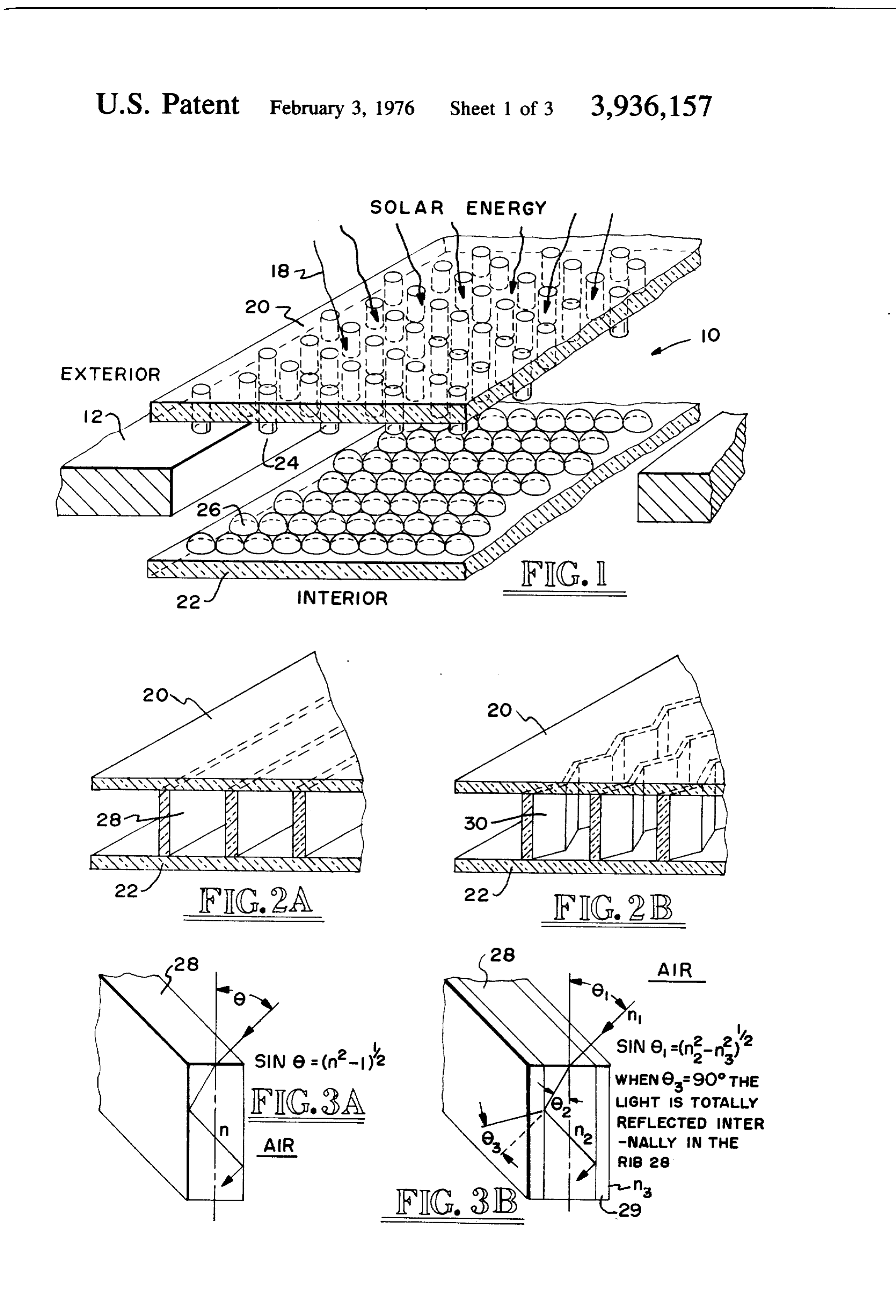
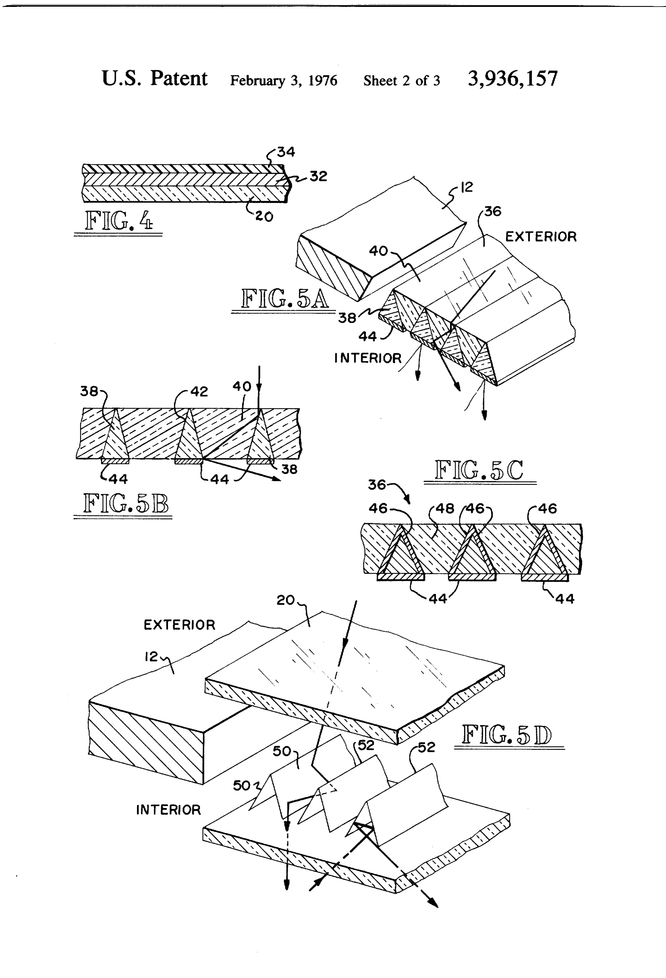
BRIEF DESCRIPTION OF THE DRAWINGS ribs which extend the length of the sheets 20 and 22. In FIG. I is an exploded, perspective view, partly in the modified embodiment depicted in FIG. 2b, the ribs section and with portions broken away of a window 0 are a plurality of sheets 30 turned on edge and bent in panel according to a ?rst embodiment of the invention a zig-zag fashion. In the embodiments of FIGS. 1, 2a together with the building wall in which it is intended to and 2b the ribs 24, 28 and 30 are made of lightweight, be mounted; optically transparent material. In still other embodi FIGS. 20 and 2b are enlarged perspective views, ments the light transmitting structural support between partly in section and with portions broken away of the sheets may be a honeycomb or other shapes. second and third alternative window embodiments; One purpose of having the ribs 24, 28 or 30, in addi FIGS. 30 and 3b are enlarged perspective views, with tion to supporting and separating the sheets 20 and 22 portions broken away and in section of the rib portions to form an insulating air space, is also to provide means of the window panels depicted in FIGS. 20 and 2b; for transmitting incident light striking the top sheet 20 FIG. 4 is an enlarged vertical view, in section, and to and through the bottom sheet 22. By providing these with portions broken away of a window sheet of the ribs, the incident light is accepted over a wider incident embodiment of FIG. I; angle than if the ribs were opaque and the only light FIG. 5a is a perspective view of a fourth alternative transmitted was light which managed to penetrate both embodiment, with portions broken away; the top and bottom sheets 20 and 22. From Snell’s law FIG. 5b is an enlarged vertical view, in section, of the 25 that n,sin6l = n,sin0z (where 0, and 02 are the incident structure depicted in FIG. 5a; angle and the refracted angle, respectively) and the FIG. 5c is an enlarged vertical view, in section, of a principle of total internal re?ection that the refracted modi?cation of the structure depicted in FIG. 5b; angle (61,) for light leaving the material having the FIG. 54' is a perspective view of a fifth embodiment of higher index (n2) of refraction into a material (such as the invention. with portions broken away and in sec a coating) of a lower refractive index (n;,) must be 90° tion; (see FIG. 3b), then
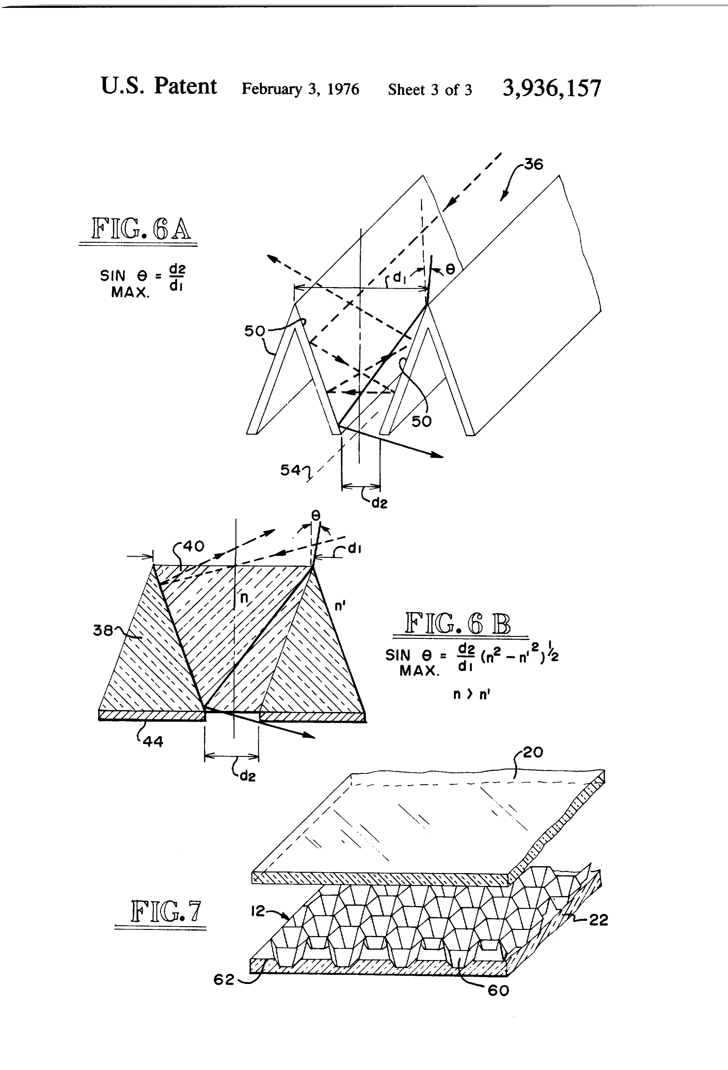
FIGS. 6a and 6b are diagrammatic illustrations for use in explaining the operation of the window panels depicted in FIGS. 5a-5d; and
FIG. 7 is a perspective view of a sixth embodiment of 35 the invention, with portions broken away and in sec tion.
where 25- maximum light acceptance angle for total inter~
DETAILED DESCRIPTION OF CERTAIN nal re?ection
PREFERRED EMBODIMENTS n, = l (for air) n, = refractive index of material of rib 28, and
Referring now more particularly to FIG. I, the win dow panel 10 of the invention is mounted in a wall of a n, = refractive index of a protective dielectric coating structure 12 and includes a pair of thin, transparent 29 on rib 28, sheets 20 and 22 which are spaced apart by a plurality where rib 28 is uncoated, n, = l and of upstanding columns or ribs 24 which are also made 45 of lightweight, light transmitting material and prefera max bly of a material which has high optical transmission qualities. In practice, the material chosen for the sheets 20 and 22 and the ribs 24 may be lightweight plastic. In Note that 6 is measured with respect to the normal of other embodiments, the top sheet 20 may be glass for 50 the top surface of the rib, and therefore the actual ruggedness. maximum acceptance angle in the above examples is As mentioned above, the window portion must be 20. In the case of wall type ribs, such as ribs 28 and 30, designed to accept solar radiation 18 over as wide an there is some advantage in aligning their longitudinal angle of incidence as possible. It also must be designed axis with the direction of travel of the sun over the to prevent heat loss through reradiation from the inte panel. When this is done the bulk of the incident light rior of the structure 12 and heat loss due to conduction will always be within the acceptance angle since the and air convection currents either between the sheets acceptance angle for light contained in all planes which 20 and 22 or in the region immediately adjacent the also contain the longitudinal axis is substantially I80". bottom sheet 22 due to the temperature differential While the above described mathematical relation~ across the window 10. ships between the angle of acceptance and the indices Means are provided for segmenting the air space of refraction are given with respect to the rib 28, it between the sheets 20 and 22 to reduce heat loss due to should be apparent that substantially similar relation conduction as well as convection air currents which ships apply to the ribs 24 and 30. Thus, light is trans would otherwise develop between the two sheets. In the ferred through the window portion by means of multi embodiment depicted in FIG. 1, the means for seg 65 ple, total internal re?ections within the ribs 24, 28 or menting the space comprises a plurality of transparent 30.
bubbles 26 on the upper surface of the sheet 22. The In some embodiments it is preferable to coat the bubbles 26 may be made ofa transparent material such sheets 20 and 22 with a transparent hard coating 32 in
Page 7
order to prevent scratching and an anti-re?ection coat Referring now more particularly to FIGS. 5c and 5d, ing 34 to minimize reflection losses (FIG. 4). Further metal or multiple dielectric layers are used for re?ec more, in some embodiments it is preferable to stack a tion in place of the wedges 38 and 40 of transparent number of window sections 10 to minimize heat losses material. In particular, in the embodiment of FIG. 5c a due to re?ection and reradiation from the interior of plurality of opposed re?ecting surfaces 46 are embed the structure 12. ded in a transparent medium 48. The opposed re?ect Referring now more particularly to FIGS. 5a and 5b, ing surfaces 46 are inclined to converge inwardly. The still another embodiment of the window section 10 is infrared re?ecting surfaces 44 are placed on the inte illustrated. In the embodiment of FIGS. 5a and Sb, a rior surface of the panel of material 48 between pairs of 0 opposed converging surfaces 46 in a manner similar to panel 36 of optical valves admit incident light to the structure but blocks the escape of a large portion of the embodiment of FIGS. 5a and 5b. infrared radiation emitted from within the interior of In the embodiment depicted in FIG. 5d, thin ?at the structure 12. The basic design of each optical valve laminates 50 are attached together along one edge to in the panel 36 is to provide a plurality of opposed form an inwardly opening V-shaped channel 52. A re?ecting surfaces which converge in the overall direc plurality of the V-shaped channels 52 are aligned paral tion of incident light travel through the window 10. The lel to each other and extend along the length of the re?ecting surfaces of each optical valve of the panel 36 window panel 10. The opposed re?ecting surfaces of may be in the form of a plurality of reflecting V each adjacent pair of reflecting channels 52 form a pair grooves or in a plurality of honeycomb cells but both of inwardly converging re?ecting surfaces as in the arrangements have wider openings at the top surface, other optical valve embodiments described above with that is, the surface ?rst struck by the incident solar reference to FIGS. 5b and 6c. The inner end of each radiation, than at the bottom surface, that is, the sur V-shaped channel 52 is open so that infrared radiation face closest to the interior of the structure 12. The emitted from within the structure 12 strikes the interior optical valve panel 36 may be composed of combina surfaces of the V-shaped channel 52 and is re?ected 25 back by multiple re?ections within the V-shaped chan tions of metal and dielectric materials.
The optical valve panel 36 may be substituted for the nels 52 as indicated by the dashed line path in FIG. 5d. panel 10 but is more preferably used in conjunction The infrared re?ecting surfaces may take different with it. For example, in some embodiments the panel shapes in other embodiments. For example, they may 10 and the optical valve panel 36 are stacked in sand 30 be ?at, corner-cubed or even hemi~cylindrically con cave and are not necessarily the backsides of the lami wich fashion with the panel 10 on the exterior. This embodiment benefits from the combined characteris nates 50.
The re?ective surfaces 46 and 50 may be polished tics of both windows, namely the high insulative quali metal or multiple layers of dielectric coatings o_ver ties to convective and conductive heat loss of the panel metal surfaces to form a re?ective laminate. One ad 10 and the barrier qualities of the optical valve panel 35 vantage of dielectric coatings over metal surfaces is 36 to escaping infrared radiation from the interior of that dielectric coatings can be made with a higher re the structure 12. Numerous other combinations of ?ection coefficient than the metal surfaces alone but these embodiments to satisfy speci?c light transmitting generally for smaller incident angles and wavelength and heat conservation requirements will be apparent to ranges.
those skilled in the art. 40 One important consideration in the design of these In the embodiment depicted in FIGS. 5a and Sb, a optical valves of the panel 36 is the acceptance angle plurality of inwardly converging V-grooves are formed for solar radiation. If the light striking the exterior of by constructing the panel 36 of outwardly pointing, the panel 36 is at too large an angle with respect to the triangularly shaped wedges 38 of low refractive index normal to the panel 36, then the bulk of the incident material interspersed between inwardly pointing, trun 45 light will be re?ected or refracted out rather than be cated, triangularly shaped wedges 40 of high refractive passed through it by multiple re?ections. In all planes index material. The terms inwardly and outwardly as containing the apex line of the V-groove, however, all used here are with respect to the interior and exterior incident angles of solar radiation are accepted. With of the structure 12. The incident solar radiation is reference to FIG. 5a, incident light striking the panel transmitted through the high refractive index medium 50 36 in a plane which is normal to the panel 36 and which 40 and is re?ected at each interface formed between a passes through the lower apex of any given wedge 40 wedge of high refractive index material 40 and a wedge will be accepted. Thus, it is preferable to align the of low refractive index material 38. Thus, these inter longitudinal axes of the optical valves in the panel 36 faces formed by the discontinuities in the refractive with the direction of the sun’s travel over the panel 36. indices are effectively re?ective surfaces 42 for the Referring now more particularly to FIG. 6a, which is incident solar radiation. Such a reflecting surface 42 if an enlarged and perspective view of the embodiment formed on the opposite, inwardly converging sides of depicted in FIG. 5d, the apex line is de?ned as a line 54 each wedge 40 and thus light entering from the exterior which is centered between the opposed re?ecting sur surface of the wedge 40 is multiply re?ected inwardly. faces 50 at their closest points and parallel to the exte In order to prevent the escape of infrared radiation 60 rior surface of the panel 36. For light striking the exte from the interior of the structure 12, a plurality of rior of the panel 36 in a plane which is normal to the infrared reflecting surfaces 44 which face the interior apex line 54 it can be shown that the acceptance angle of the structure 12 are provided on the bottom of each of the incident light is:
wedge 38. Therefore the optical valve panel 36 is highly transmitting for incident solar light coming from 65 the exterior of the structure I2 and highly re?ecting for the infrared emitted from the interior of the structure
l2 in the opposite direction.
Page 8
and the full acceptance angle, 26",”, (Le. the light strik In all of these embodiments it has been assumed that ing from either side of a line normal to the top of the the desired objective is to admit light while retaining panel 36) is: heat. In other applications, however, it may be desir able to reverse the orientation of these embodiments so 11L as to keep out heat and let a portion of the incident
max ‘1| light into the interior of the building structure. The terms and expressions which have been em ployed here are used as terms of description and not of where d, is the width of the smaller end, and d, is the limitation, and there is no intention, in the use of such width of the larger end of the V»shaped groove formed terms and expressions, of excluding equivalents of the by the opposed re?ecting surfaces 50. For any larger features shown and described, or portions thereof, it angle the incident light will not be multiply reflected being recognized that various modi?cations are possi toward the apex but instead will be re?ected back out ble within the scope of the invention claimed. of the V-groove. What is claimed is:
When the groove consists of two different dielectrics, l. A window panel comprising a pair of spaced apart as depicted in FIGS. 6b and 5b, for example, the full transparent sheets, perpendicular supports for keeping acceptance angle can be shown* to be: the sheets spaced apart and for segmenting the air space between the sheets to prevent heat loss due to 11: convective air currents, the supports being made of 20.....- = 2 sin“ { d‘ 20 light transmitting material arranged to transmit inci dent light striking the window within a predetermined where n = refractive index of wedge 40, and n’ = re angle of acceptance through the window panel by fractive index of wedge 38. means of multiple total internal re?ections. ‘See Fiber Optics, pp. l8-2l, by N. S. Kaparly, the present applicant 2. A window panel for use in a hollow structure for (Academic Press, New York [967). 25 transmitting incident light into the interior of the struc While in the above described embodiments, the opti ture comprising a plurality of opposed re?ecting sur cal valve panel 36 is illustrated in the ?gures as com faces arranged in a panel for transmitting the incident prising a plurality of V~grooves, in other embodiments light into the structure by multiple reflections, the (FIG. 7), as mentioned above, it has a honeycomb cell panel of re?ecting surfaces including a ?rst set of elon structure 60 wherein the opening closest to the incident 30 gated, parallel, triangularly shaped, re?ectively sur light is wider than the opening which is closest to the faced wedges, each wedge having three apexes with interior of the structure 12. The opposed plane surfaces one apex pointing in the direction toward the incident inside each honeycomb cell of the structure 60 provide light, means for supporting the wedges so that the two a plurality of opposed re?ecting surfaces which operate apexes of each wedge which are opposite to the one in substantially the same manner as the V-groove ar 35 apex are spaced apart from the corresponding apexes rangements shown above so that a detailed description of adjacent wedges to thereby de?ne a plurality of of the honeycomb arrangement will be omitted. The truncated, V-shaped, re?ective surface channels, and honeycomb structure 60 may be situated between the infrared re?ecting means disposed adajcent to the two sheets 20 and 22 (as shown in FIG. 7) or it may be a opposite apexes of each wedge for re?ecting back in separate panel below the sheet 22. The plane surface frared light emitted from within the structure. area 62 of the structure 60 below and between the 3. A window panel as recited in claim 2 wherein the honeycomb cells is preferably a reflecting surface for ?rst set of wedges are made of a light transmitting the infrared radiation .emitted from within the structure material and further comprising a second set of trun~ 12. cated, triangularly shaped wedges oriented in the oppo One advantage of this design over the V~groove or 45 site direction to the ?rst set of wedges and interspersed wedge con?gurations is that it is non-axially direc between them, the second set of wedges being made of tional. As explained above, the V-groove or wedge a light transmitting material having a higher refractive structures of FIGS. 50-511 preferably are utilized with index than the material of the ?rst set of wedges so that their longitudinal axes aligned with the sun‘s direction the interfaces between the wedges of the ?rst and sec of travel over the panel so that the bulk of the incident ond sets form the plurality of V-shaped re?ective sur light will always strike within the incident angle of face channels.
acceptance. With the honeycomb structure 60, how 4. A window panel as recited in claim 2 wherein the ever, the sun’s direction of travel is not material since re?ective surfaces of the wedges comprise multiply light is accepted in the same manner for any given layered all dielectric coatings.
incident angle with respect to the normal to the panel 55 5. A window panel as recited in claim 2 wherein the for all radial directions about the panel. re?ective surfaces of the wedges comprise multiply Another advantage of the honeycomb cell structure layered metal~dielectric coatings. 60 over some othe designs is that it is very effective in 6. A window panel for use in a hollow structure for segmenting the air space between the sheets 20 and 22 transmitting incident light into the interior of the struc (in FIG. 7 embodiment or below sheet 22 in other ture comprising a plurality of opposed re?ecting sur embodiments to reduce convective heat losses. faces arranged in a panel for transmitting the incident Although the panel embodiments have been de light into the structure by multiple, total internal re?ec scribed above as generally ?at, in other embodiments tions, the panel of re?ecting surfaces including a paral they may be curved to give a concentrated effect. Fur lel set of truncated, triangularly shaped wedges, each thermore. while the panel has been described with 65 wedge having three apexes with one apex pointing in respect to its use in an external structural wall it should the direction away from the incident light, means for be apparent that it is equally suitable for use in internal supporting the wedges so that the one apex of each structural walls and with other than solar light. wedge is spaced apart from the corresponding apex of
Page 9
adjacent wedges to thereby de?ne a plurality of V larly to the sheets, for keeping the sheets spaced apart, shaped channels, the wedges being made of a ?rst light the supports being made of light transmitting material transmitting material, a second light transmitting mate arranged to transmit incident light striking the window rial, of a lower refractive index than the refractive within a predetermined angle of acceptance through index of the ?rst light transmitting material, the second the window panel by means of multiple, total internal light transmitting material ?lling the V-shaped chan re?ections.
nels such that re?ective, dielectric surfaces which con verge toward the interior of the structure are formed at 8. A window panel as recited in claim 7 wherein the the interfaces of the wedges and the second light trans supports are in the shape of rods. mitting material, the converging re?ective surfaces 9. A window panel as recited in claim 7 wherein the serving to condense the bulk of the incident light so supports are in the shape of honeycomb cells. ' that is passes solely through the wedges. 10. A window panel as recited in claim 7 further 7. A window panel as recited in claim 6 further com comprising means for segmenting air spaces between prising a pair of spaced apart transparent sheets and the sheets. ' spaced apart support columns, arranged perpendicu 15 it i * ill II!
Provenance
- Collection
- Cited prior art
- Original PDF
- patentimages.storage.googleapis.com →
- Filed
- 1974-04-22
- Pages
- 9
- Method
- pdftotext (the PDF's own text layer) + pdftoppm 300dpi page scans
- Source
- Google Patents bibliographic record
- Granted
- 1976-02-03
- Inventors
- Narinder S. Kapany; Kaptron Inc
- Transcribed from
- patentimages.storage.googleapis.com →