patent · US3736747
Combustor
5 June 1973
Page 1 — bibliographic record
United States Patent (19) 11 3,736,747 Warren (45) June 5, 1973 54 COMBUSTOR FOREIGN PATENTS OR APPLICATIONS 76) Inventor: Glenn B. Warren, 1361 Myron St., 762,596 1956 Great Britain....................... 60/39.65 Schenectady, N.Y.
(22 Filed: July 9, 1971 Primary Examiner-Carlton R. Croyle Assistant Examiner-Robert E. Garrett (21) Appl. No. 161,179 Attorney-Joseph V. Claeys and Charles W. Helzer 52 U.S. Cl..................................60/39.65, 60/39.66 (57) ABSTRACT 51 Int. Cl............................... F02c 3/00, F02c 7/12 58 Field of Search........................... 60/39.65, 39.66 A combustor is provided having a housing with a liquid coolant jacket and having a combustion 56) References Cited chamber which is divided into separate combustion UNITED STATES PATENTS zones. Each zone is regeneratively cooled by members disposed within the combustor which are arranged to 2,654,996 10/1953 Boninsegni.......................... 60/39.65 swirl the process air and to contain and cool the 2,617,255 1 1/1952 Niehus................................ 60/39.65 flame. The heat removed from the flame is returned to 2,603,064 7/1952 Williams.............................. 60/39.65 the process air before it is supplied for staged com 3,433,015 3/1969 Sneeden.............................. 60/39.65 2,61 1,241 9/1952 Schulz................................. 60/39.66 bustion. The combustor is capable of operating at high 2,560,207 7/1951 Berggren et al..................... 60/39.65 temperatures, high equivalence ratios and high effi 2,577,918 11/1951 Rowe .................................. 60/39.65 ciencies.
3,352,106 l l 11967 Pianko ................................ 60/39.65 2,579,614 12/1951 Ray..................................... 60/39.65 14 Claims, 6 Drawing Figures
Z242 t AH awawww.www.www.wwaravawww.www.
XVAWA awaxw
RSS NQSSSSSSN
Page 2
Drawing sheet — no readable text.
Page 3
Drawing sheet — no readable text.
Page 4
Drawing sheet — no readable text.
Page 5
COMBUSTOR therein. These surface means are operative to cool each of the first and second hollow members and im
This invention relates generally to combustors and part the first direction helical motion to the air flowing more particularly to combustors which are capable of in each of the first and second air pssage means. The operating at high temperatures and high efficiencies 5 air passage means supply the heated air to the respec over wide ranges of operating conditions. The present tive secondary and tertiary combustion zones. invention is particularly suited for combustor construc For applications, such as for gas turbines, where it is tion for power plants as well as for cooled reciprocating desired not to confine the hot combustion products to piston engines and gas turbines. a hot central core at the exit, the extended surface In order to attain high efficiencies over wide ranges O means are arranged to impart to the air provided to the of operating conditions, wherein large amounts of en tertiary combustion zone a helical motion in the direc ergy are released per unit volume, the problems of ex tion opposite to the first direction. The consequent tur cessive flame temperatures and of excessive heat loss bulent mixing of the relatively colder unreacted air and must be avoided. Excessive flame temperatures may hot combustion products provides hot gases at the out result in local temperature levels which may be so high 15 let which have a uniform temperature across the com as to cause structural damage to the combustor and bustion chamber.
cause the production of large quantities of oxides of ni The novel features believed characteristic of this in trogen. In instances where cooling means had been pro vention are set forth with particularity in the appended vided in the prior art combustors, incomplete combus claims. The invention itself, however, both as to its or tion and lowered operating efficiencies had been in 20 ganization and method of operation together with fur curred. This invention overcomes these problems to a ther objects and advantages thereof may best be under great extent by dividng the combustion chamber into a stood by reference to the following description taken in plurality of effectively separate combustion zones; conjunction with the accompanying drawings, and in preferably the combustion chamber provides for pri which:
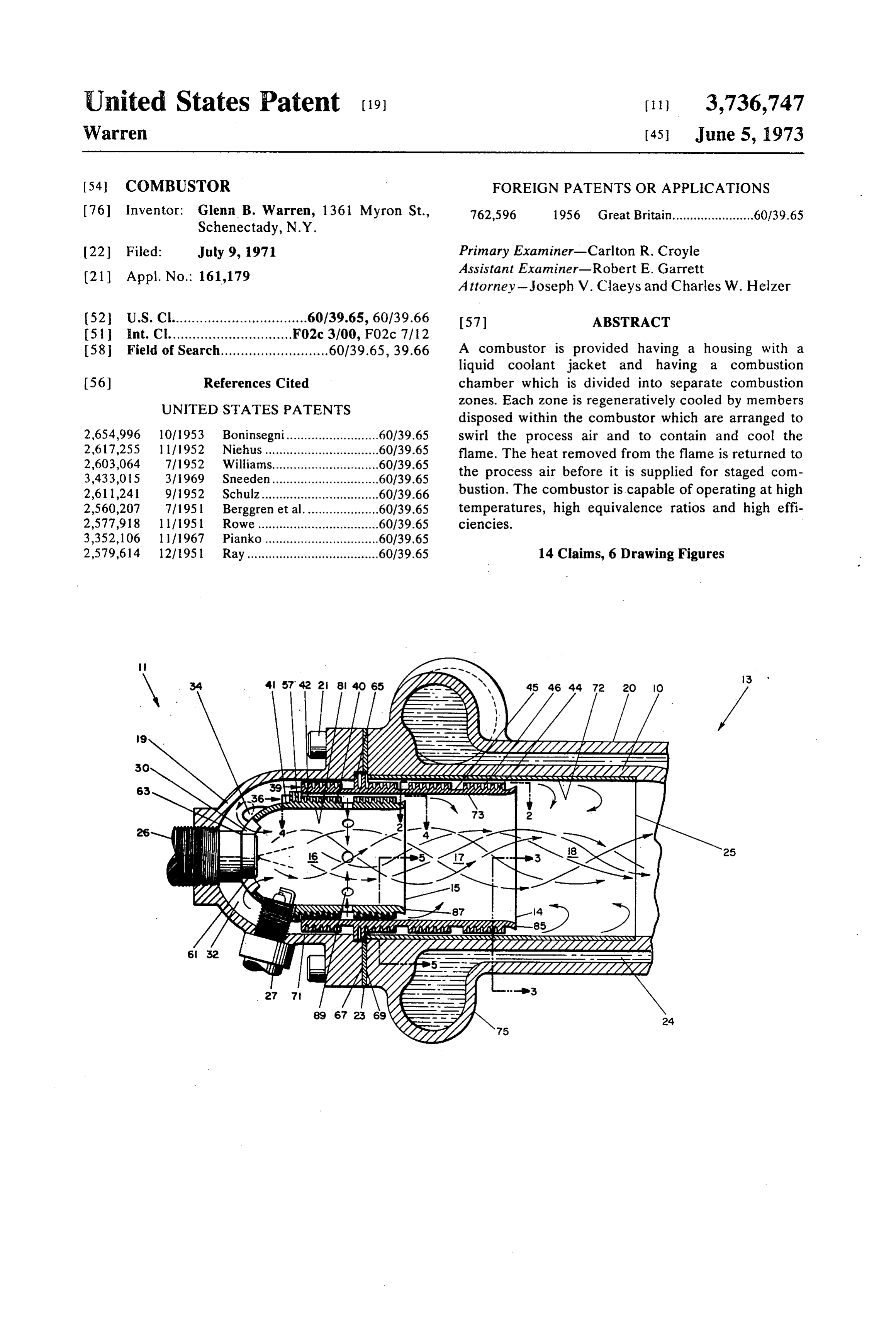
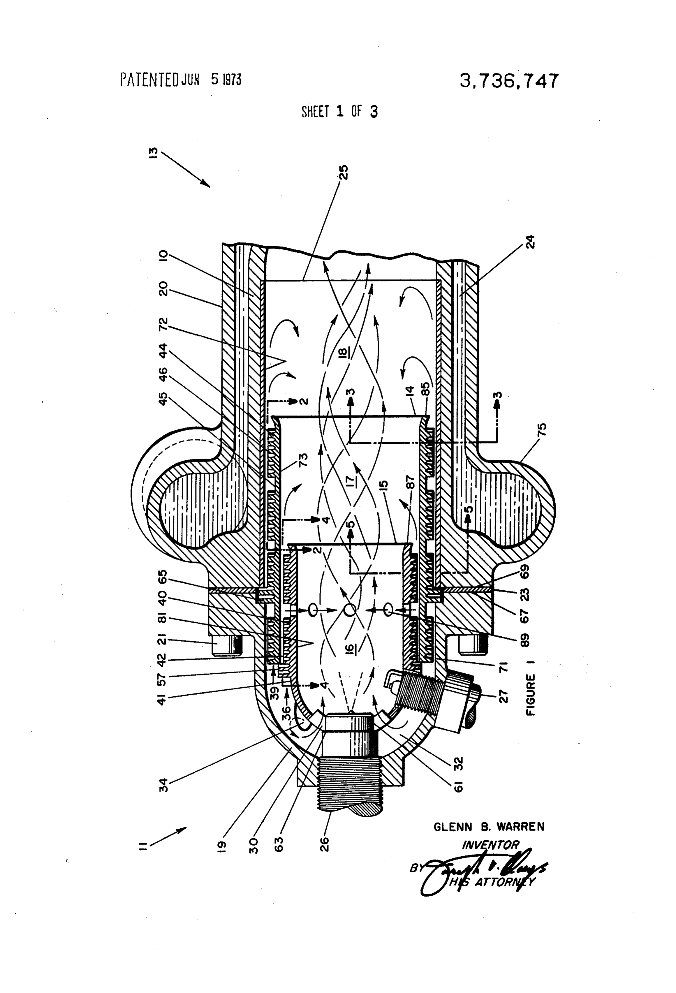
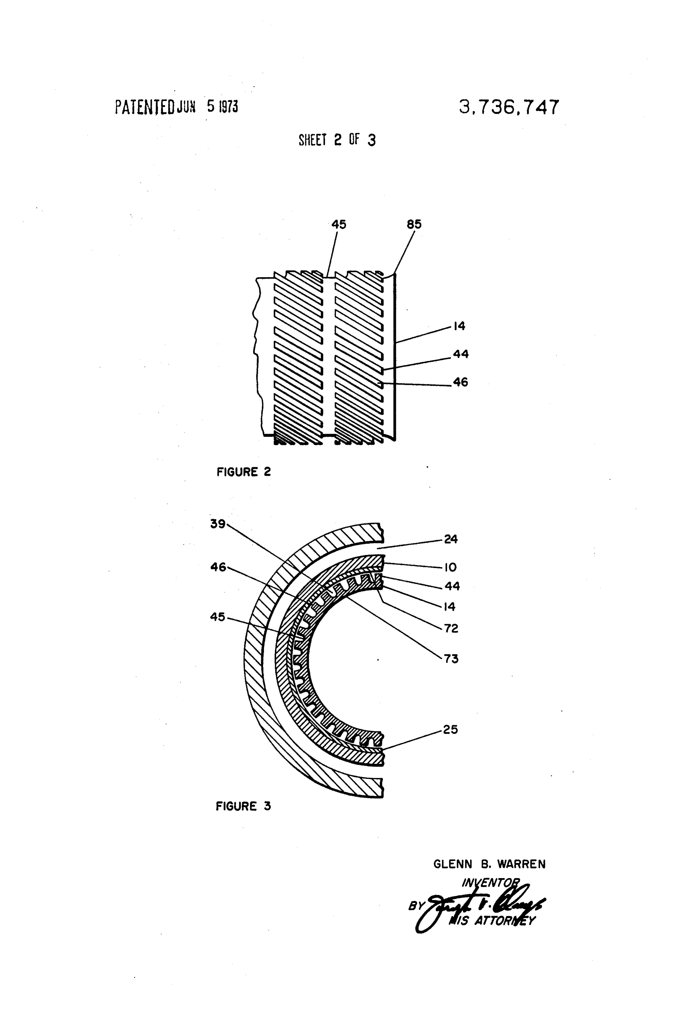
mary, secondary and tertiary zones. Air to the primary 25 FIG. 1 is a diagrammatic partial section view of one zone is controlled to provide a fuel-rich flame and the embodiment of the combustor of this invention; air to the secondary and tertiary zones is controlled to FIG. 2 is an outside view of a portion of the outer hol complete the combustion process in staged combus low member in the direction 2-2;
tion. The combustor further includes means whereby FIG. 3 is a section view of a portion of the combustor the flame in the respective zones is regeneratively 30 in the direction 3-3;
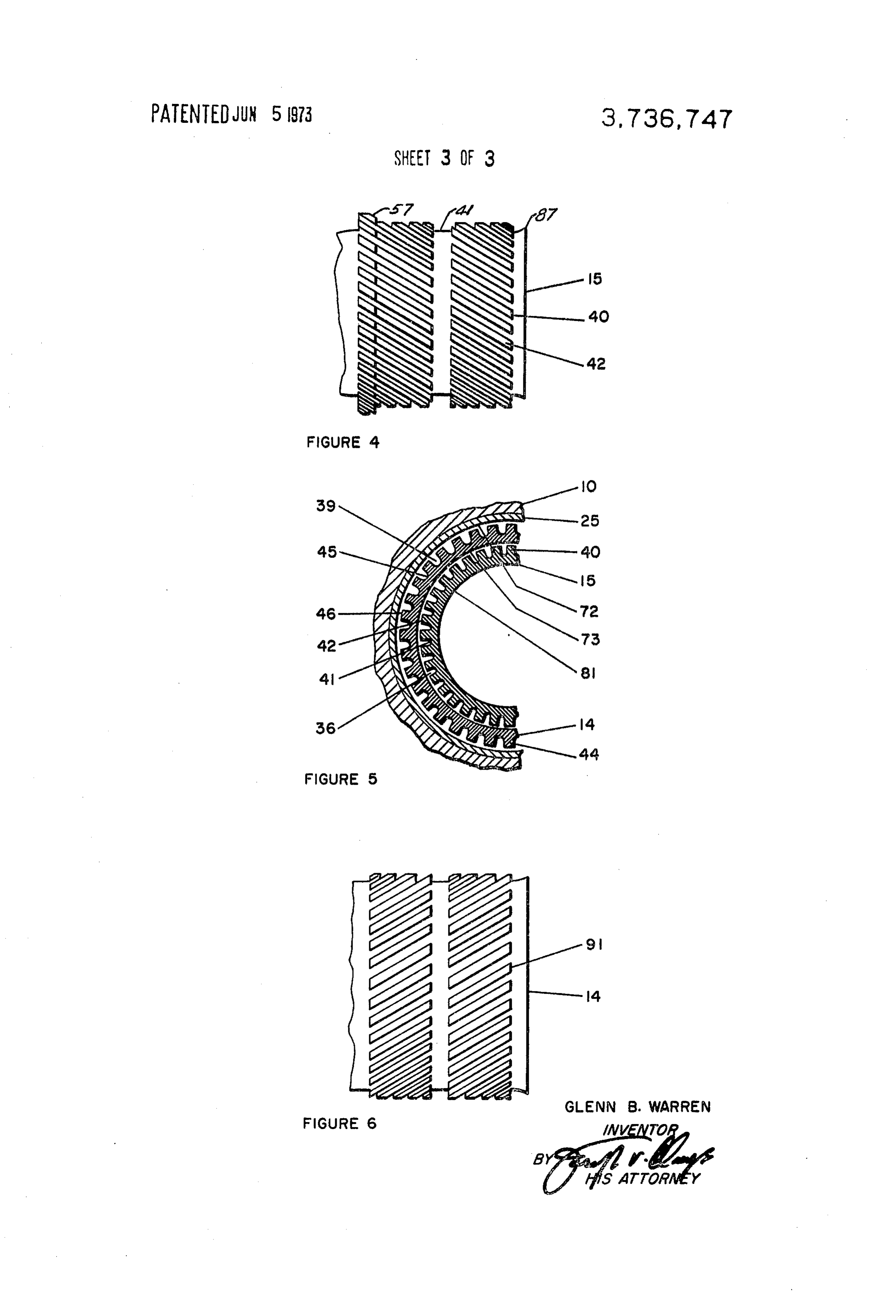
cooled and contained along the longitudinal center FIG. 4 is an outside view of a portion of the inner hol portion of the combustion chamber. That is, the heat low member in the direction 4-4;
removed from the flame is returned to the secondary FIG. S is a section view of a portion of the combustor and tertiary zones with the air supplied thereto thereby 35 in the direction 5-5; and providing high overall efficiency. FIG. 6 is an outside view of a portion of an alternative Accordingly, it is an object of this invention to pro outer hollow member in the direction 2-2. vide a new and improved combustor capable of opera Referring now to the drawings there is shown in FIG. tion at high temperatures and over wide ranges of load 1 a combustor in accordance with one embodiment of conditions and high efficiency. this invention. The combustor includes a housing It is another object of this invention to provide new 40 means 10 having an inlet end 11 and an outlet end 13. and improved combustor having regenerative flame The combustor also includes first and second hollow cooling means whereby a higher space heat release rate members 14 and 15 disposed within the housing means of combustion is obtained while maintaining a flame 10 in radially spaced-apart axially overlapping relation temperature level which is relatively low. ship to define therewith a combustion chamber having Briefly stated, in accordance with one aspect of this 45 a primary combustion zone 16, a secondary combus invention a new and improved combustor comprises a tion zone 17 and a tertiary combustion zone 18. hollow housing means with first and second hollow Conveniently, housing means 10 may be provided by members disposed therein in radially spaced-apart axi a head portion 19 suitably connected in sealing rela ally overlapping relationship to define with the housing 50 tionship with a body portion. 20. For example, head means a combustion chamber having an inlet and an portion 19 may be connected by bolts 21 and seal 23 outlet, and primary, secondary and tertiary combustion to the body portion 20 to provide the complete housing zones therebetween. The combustor is provided with means 10. Preferably, especially for high temperature means to supply a controlled flow of fuel as well as operation, the body portion 20 may be provided with means to supply a controlled forced flow of air to the a liquid cooling jacket 24 and an inner liner means 25. primary combustion zone. This air if given a first direc 55 Also, to avoid the problems associated with providing tion of helical motion. As a result of this motion centrif a high temperature-high pressure seal, the connection ugal force urges the colder relatively denser unreacted between the head portion 19 and the body portion 20 air towards the inside surfaces of the hollow members may be made at a point remote from the high tempera and the hot relatively light gases of the combustion re 60 ture region of the combustor.
action towards the center of the chamber. Additionally, The combustor is provided with a suitable means, the first and second hollow members provide regenera shown as nozzle means 26, to supply a controlled flow tive flame cooling. The combustor is also provided with of fuel to the primary combustion zone 16 and a suit means to supply a controlled forced flow of air having able ignition means, shown as a spark plug 27. the first direction of helical motion to each of the sec The combustor of this invention is capable of attain ondary and tertiary combustion zones. The latter 65 ing high combustion efficiency over a wide range of op means include first and second annular air passage erating cnditions. It is particularly suited to high output means each having extended surface means extending operation in which the exit gases may become very hot.
Page 6
While damaging temperatures may be obviated by pro To this end, the combustor is provided with means to viding a liquid cooling jacket for the combustor, the re supply a forced flow of air to the primary combustion sulting loss of heat to the cooling liquid could greatly zone 16. The air so supplied has a helical motion im lower the combustor efficiency. It is an important fea parted to it in a given direction so as to cause swirling ture of this invention, therefore, to provide means for of the air and fuel within primary combustion zone i6 providing both flame containing and cooling functions so that when ignited by spark plug 27 the hot lighter with little or no heat loss. This is accomplished in ac combustion gases will be confined to the longitudinal cordance with this invention by causing the combustion center of the combustion zone and the cooler heavier products to be swirled in a helical motion in all of the portions of the combustion gases will be urged into combustion zones while at the same time providing re 10 contact with the outer walls of the member 16 defining generative flame cooling. That is, the heat transferred the primary combustion zone. This swirling action pro to the cooling air used to cool the combustion zones is vides a significant cooling effect to the walls of the returned to the combustion process at a point distant combustion zone.
from the one at which it was removed with little or no In the arrangement illustrated a suitable nozzle heat loss. Accordingly, the peak combustion tempera 15 means 30, which may be a plurality of inclined blades, ture is reduced with little or no heat loss. is disposed in the end wall of member 15 so as to com Moreover, since the quantity of oxides of nitrogen municate on one side with an air plenum 32 and on the generated is generally determined by peak temperature other side with the primary combustion zone 16. Air levels of regions through which the combustion gases plenum 32 is adapted to be connected with a suitable pass, the regenerative cooling provided in a combustor source of air under pressure (not shown). Advanta of this invention will thus provide low oxide of nitrogen geously, the air supplied to plenum 32 may enter tan levels in the combustion products as described in more gentially through supply ports 34, only one of which is specific detail hereinafter. shown, to provide initial helical motion to the air in the A combustor of this type is inherently capable (so 25 plenum. Nozzle means 30 not only meters or controls long as excess air over stoichiometric is provided) of the amount of air supplied to the primary combustion giving combustion products which are low in CO and zone 16 but also imparts the desired helical motion to unburned hydrocarbons. it so that the hot lighter combustion gases will be con Unless special precautions are taken, however, the fined to the longitudinal center of the zone and the nitrogen oxide (NOx) components of the exhaust, al cooler heavier gases will be urged into contact with the though inherently lower than in an explosion cycle en 30 walls thereof to provide a cooling effect therefor. gine because of lower peak combustion temperatures, To provide for the desired operation of the combus may still be higher than permitted by the new Federal tor, a controlled forced flow of air is also supplied to Air Pollution Standards for automotive engines. the secondary and tertiary combustion zones. Also, the Accordingly, the combustor of this invention is made 35 combustion zones must be suitably cooled in a manner to operate with the so-called "staged combustion tech which will prevent damage from excessive temperature nique." This technique has been used in a few large and allow for a desired 'staged combustion' effect all steam turbine power plant boiler furnaces by some with little or no loss of heat.
boiler manufactureres, but so far as I am aware it has As indicated in connection with the supply of air to never before been incorporated into a combustor capa 40 the primary combustion zone 16, partial cooling may ble of operating at high temperatures and pressures and be effected by providing the swirling action to confine over a large output range. the lighter hot combustion gases to the longitudinal The principle of operation of such staged combustion center of the combustion zone. For the higher output so far as generation of low NOx is concerned depends condition additional cooling must be provided. upon the basic physics of such combustion in that the 45 In accordance with this invention means are provided extent of NOx formation is first a power function of the to supply a controlled flow of air to the secondary and temperature (probably fifth power) and second of the tertiary combustion zones which air has imparted to it amount of excess oxygen available. This means that the desired helical motion to produce the swirling ef such NOx is a maximum at about 10% - 15% excess air fect. Also, the air is utilized to cool the combustion over that required for stoichiometric. The amount of 50 zones and the heated air is then utilized in the second NOx is also a function of the dynamics or speed of for ary and tertiary combustion zones. That is, the air sup mation which is also a drastic function of the tempera plied to the secondary and tertiary combustion zones is tures at which the excess oxygen is made available. first utilized to cool the primary and secondary com Considering these laws it follows that if with an ulti 55 buation zones and the flame contained therein before mate equivalence ratio at the exit of say 0.7 (lean) the entering the appropriate secondary and tertiary com primary zone is kept at an equivalence ratio of 1.2 bustion zones. Since the heat transferred to the air in (rich), the flame in such primary zone would be lower providing the cooling of such combustion zone is then in temperature than stoichiometric and little or no ex utilized in the combustion process such cooling is ef cess oxygen would be present. If then this flame is fur 60 fected with little or no loss of heat. ther cooled either by a liquid cooling jacket, or by re In accordance with this invention the air for the sec generative air cooled walls before the remainder of the ondary combustion zone 17 is supplied from the ple combustion air is added, then, when it is added the num 32 through an annular air passage means 36 pro lower resulting temperature will reduce both the extent vided between the first member 4 and the second of NOx formation by temperature alone, and will also 65 member 15. As shown, one end of annular air passage so slow the oxidation process down in time as to reduce means communicates with the air plenum 32 and the the total NOx formed before the gases are further other end communicates with secondary combustion chilled by the prime mover into which they are fed. zone E7.
Page 7
Similarly, the air for the tertiary combustion zone 18 peratures of housing 10, liner means 25 and members is supplied from plenum 32 through annular air passage 14 and 15 are correspondingly higher. The temperature means 39, one end of which communicates with ple ranges between low and high output operation of liner num 32 and the other end of which communicates with means 25 and members 14 and 15, particularly where the tertiary combustion zone 18. 5 exposed to the flame and hot combustion products, are To provide for the desired regenerative air cooling of much greater than that of housing 10. The more rigid the primary and secondary combustion zones extended housing, however, constrains their radial thermal ex surface means are provided on each of the hollow pansion and causes them to undergo circumferential members 14 and 15 over which the air being supplied crushing and radial shortening during the periods of to the secondary and tertiary combustion zones passes; O early operation. Consequently when operating temper the extended surface means being arranged and atures are reduced as at lower loads, liner means 25 adapted to impart the desired helical motion to the air and members 14 and 15 will remain in size-on-size rela as well. tionship with opposing surfaces at their ends closer to In the arrangement shown member 15 is provided inlet end 11 only, but will be spaced apart from oppos with extended surface means, shown as a plurality of 15 ing surfaces in portions which had been exposed to the fins 40 integral with the outer surface 41 of member 14 flame and hot combustion products due to contraction and extending into the annular air passage means 36. of the circumferentially crushed members. Fins 40 terminate in the end surfaces 42. Also, fins 40 Utilization of the thermal fitting just described of are arranged as shown more clearly in FIG. 4 to impart members 14 and 15 and liner means 25 within each the desired helical motion to the air supplied through other and within housing 10 is a very inexpensive and air passage means 36 and passing over such fins to pro simple way of providing the desired operating relation vide the desired regenerative cooling of the primary ship of the components. When members and liner combustion zone 16 and the flame contained therein. means are spaced apart during combustor operation at Similarly, the member 14 is provided with extended low output, excessive cooling of the fuel-air mixture by surface means, shown as a plurality of fins 44 integral 25 members 14 and 15 and liner means 25 is avoided at a with the outer surface 45 of member 14 and extending time when heat losses to the housing 10 and water into the annular air passage means 39. Fins 44 termi jacket 24 cannot be afforeded. The tight thermal fitting nate in end surfaces 46. The arrangement of the fins 44, provides for increased cooling of members 14 and 15 shown in more detail in FIG. 2 is such that the desired and liner means 25 when the combustor is operating at helical motion is imparted to the air flowing in passage 30 high output and increased flame and metal cooling of 39. the liners is desired. At the corresponding elevated Member 15 may be fitted size-on-size within member temperatures the members and liner means grow radi 14 and held in axial alignment by means of a radially ally outwards to cause the fin surfaces 46 to enter into raised portion 57 offins 40. Added support for member 35 butting relationship with the confronting inside sur 15 may be provided by fitting blades 30 size-on-size on faces 71 and 72 of the housing 10 and the liner means surface 61 of fuel nozzle 26 in axial disposition against 25, respectively, and the fin surfaces 42 with the con a suitable step 63. Member 14 may be similarly fitted fronting inside surface 73 of member 14. Similarly liner size-on-size within housing 10 and held by means of a means 25 enters again into a size-on-size fit with hous radial raised portion 65 of fins 44 extending between ing 10.
the surfaces 67 and 69 of head portion 19 and body 40 To prevent undue thermal stress in housing 10 at high portion 20 respectively. Some axial crushing of por combustor output the liquid cooling jacket 24 is pro tions 65 may take place as bolts 21 are tightened to vided with a suitable relatively more flexible portion 75 cause surfaces 67 and 69 to be brought into sealing re which is capable of accommodating the entire range of lationship on seal 23. differential thermal distortions which may be encoun Similarly, if provided, liner means 25 is fitted size-on 45 tered.
size within housing 10 with member 14 fitted size-on In operation, fuel and air are fed into the primary size within it. Liner means 25 may extend within hous combustion zone 16. Ignition may be provided by spark ing 10 for any suitable axial distance. Conveniently plug 27 or by any other suitable means. The air sup liner means 25 may extend from near surface 69 of 50 plied to plenum 32 may enter tangentially (one supply housing 10 to a point axially distance from member 14 port 34 is shown) to provide initial helical motion and and into tertiary combustion zone 18. is divided into primary, secondary and tertiary por In operation at any given airflow the combustor out tions: the primary air is that required to sustain com put and exit temperature depends upon the quantity of bustion under all operating conditions, while the sec fuel injected relative to the air flow. At low output it 55 ondary and tertiary air is that required to complete the has been observed that the flame is therefore relatively combustion process in staged combustion, for modula small and is confined to the inlet end of the combustion tion of the burning rate and for cooling purposes. chamber within member 15. Under these operating As already stated, blades 30 are adapted to meter the conditions the primary air is adequate to provide com air into the primary combustion zone 16 to provide a plete combustion and the secondary and tertiary air fuel rich-fuel air mixture. They are adapted also to pro provide cooling. The temperatures of housing 10, liner 60 vide helical motion to the primary air thus forming a means 25 and members 14 and 15 are correspondingly primary vortex which cooperates in containing the low. When the combustor operates at high output, the combustion reaction away from the inside surface 81 of flame region may extend axially throughout the entire member 15 by forming a helical vortex of hot gases combustion chamber. Under these operating condi 65 within the longitudinal center of the combustion cham tions the primary air is insufficient for the combustion ber. In this regard, centrifugal force will urge the colder process and the secondary and tertiary air are provided relatively denser unreacted air towards the inside sur both for cooling and to complete combustion. The tem face 81 and the hot relatively light gases of the combus
Page 8
tion reaction will be displaced towards the center of the viding a distribution of 20% primary air, 10% flame sta chamber. The effect is the same as enclosing the com bilizing air, 30% secondary air and 40% tertiary air. bustion process in a "pipe' disposed along the axis of The combustor of this invention is capable of attain the combustion chamber, the "pipe' being formed by ing high combustion efficiencies over wide ranges of the swirling relatively colder air. The heat acquired by operating conditions. The provision of liquid cooling of member 15 in effecting the desired flame cooling is re the housing and of regenerative cooling of the flame turned to the secondary air coursing over fins 40 thus and swirling of the combustion air permits the combus preheating it. Member 15, consequently, is capable of tor to be operated at high equivalence ratios and at providing the desired thermal environment for the pri high temperatures with the hot combustion products mary combustion process while, at the same time, con 10 confined to a central core. Since, in addition, the pro tributing towards an overall combustor heat economy duction of oxides of nitrogen in the combustion prod by regenerative air heating. ucts is low, the combustor of this invention is particu The secondary air flows through the inner air passage larly useful as an external combustor of a suitably means 36 and enters the secondary combustion zone cooled reciprocating piston engine similar to the one 17 at a point axially distant from the inlet end portion 15 disclosed in U.S. Pat. No. 3,577,729, issued in the 11 of the combustor. Fins 40, which the secondary air name of Glenn B. Warren.
traverses, are arranged and adapted to impart a helical In the embodiment of the invention described in con motion to the air forming a secondary vortex in the nection with FIGS. 1 through 5 the primary, secondary same direction as the primary vortex. The secondary and tertiary air were all given a helical motion in the air not only aids in staged combustion but also assits in same direction. In such an arrangement the hot gases containing the hot combustion products away from the are confined to the longitudinal center of the combus inside surface 73 of member 14 in the manner de tion chamber due to the swirling action and such nar scribed with respect to the primary vortex. The heat ac row hot centrally confined gases extend to the exit end. quired by member 14 in effecting desired flame cooling This is a very desirable and advantageous arrangement is returned to the tertiary air coursing over fins 44 thus 25 for many applications especially for an application with preheating it. Member 14 consequently is capable of an engine vof the type disclosed in the foregoing U.S. providing the desired lower temperate environment for Pat. No. 3,577,729.
the secondary combustion process while, at the same For certain other applications such as in a gas turbine time, contributing further towards an overall combus for example this could be undesirable and it would be tor heat economy by regenerative air heating. 30 preferable to have the combustion spread out at the
The tertiary air flows through the outer air passage exit end. That is, a more uniform temperature profile means 39 and enters the tertiary combustion zone 18 should be provided across the exit end of the combus at a point axially distant from member 15. Fins 44, tion chamber to prevent excessive local heating of the which the tertiary air traverses, are arranged and turbine buckets.
adapted to impart a helical motion to the air forming 35 This more uniform temperature distribution of the a tertiary vortex in the same direction as the primary combustion gases can be very readily provided in ac and secondary vortices. Again the tertiary air aids in cordance with another embodiment of the invention. In staged combustion but also assists in containing the hot this embodiment the combustor would be constructed combustion products away from the inside surface 72 in substantially the same manner as that described ex of liner means 25 in the manner already described. 40 cept that the direction of the helical motion imparted Control over the secondary and tertiary air may be to the tertiary air would be made opposite the direction effected by providing the members 14 and 15 with of the helical motion imparted to the primary and sec flared ends 85 and 87, respectively. Additionally, out ondary air.
ward growth of members 14 and 15, when the combus 45 This can be very readily effected by merely arranging tor is operated at higher output, causes a reduction in the fins on the surface of member 14 in the opposite ar the cross-sectional areas of the outer air passage means rangement to the fins on the surface of member 15. 39 and the inner air passage means 36. As a conse This can be seen more clearly by a comparison of quence the quantity of secondary and tertiary air sup FIGS. 2, 4 and 6. In FIGS. 2 and 4 the fins 40 of the plied to the combustion chamber is automatically re 50 member 14 are arrnaged in the same direction as the duced and that of the primary air is increased which is fins 44 on the surface of member 15 so that the second a desirable condition. ary and tertiary air will rotate in the same direction. Stabilization of the flame is done in any convenient On the other hand, in FIG. 6 the fins 91 on the sur manner such as by providing holes 89 in member 15 face of member 14 are shown arranged in a direction communicating on one side with the inner air passage 55 opposite the fins 44 on member 5 so that the motion means 36 and on the other side with the primary com imparted to the secondary air by fins 44 will be in a di bustion zone 16. The inflow of stabilizing air provides rection opposite that imparted to the tertiary air by the a region of slightly elevated pressure which prevents fins 91. Thus while the tertiary air aids in staged com flame blow-out at low output operation. bustion it brings the rotary movement of combustion As already described, combustion air control is an 60 products within the combustion chamber to zero and important feature in the combustor according to this provides increased turbulent mixing of the relatively invention. Variations in the rate of air flow provide colder unreacted air and hot combustion products and variations in the combustion process and pattern and in tends to bring about a more uniform temperature pro the temperature levels of component members. An im file in the outlet combustion gases by breaking up the portant feature is that the amount of air required for hot center.
combustion is introduced into the combustion chamber 65 Although there has been described what are consid as primary, secondary and tertiary air. Good combustor ered at present to be preferred embodiments of the in performance may be achieved, for example, when pro vention, many modifications and changes may occur to
Page 9
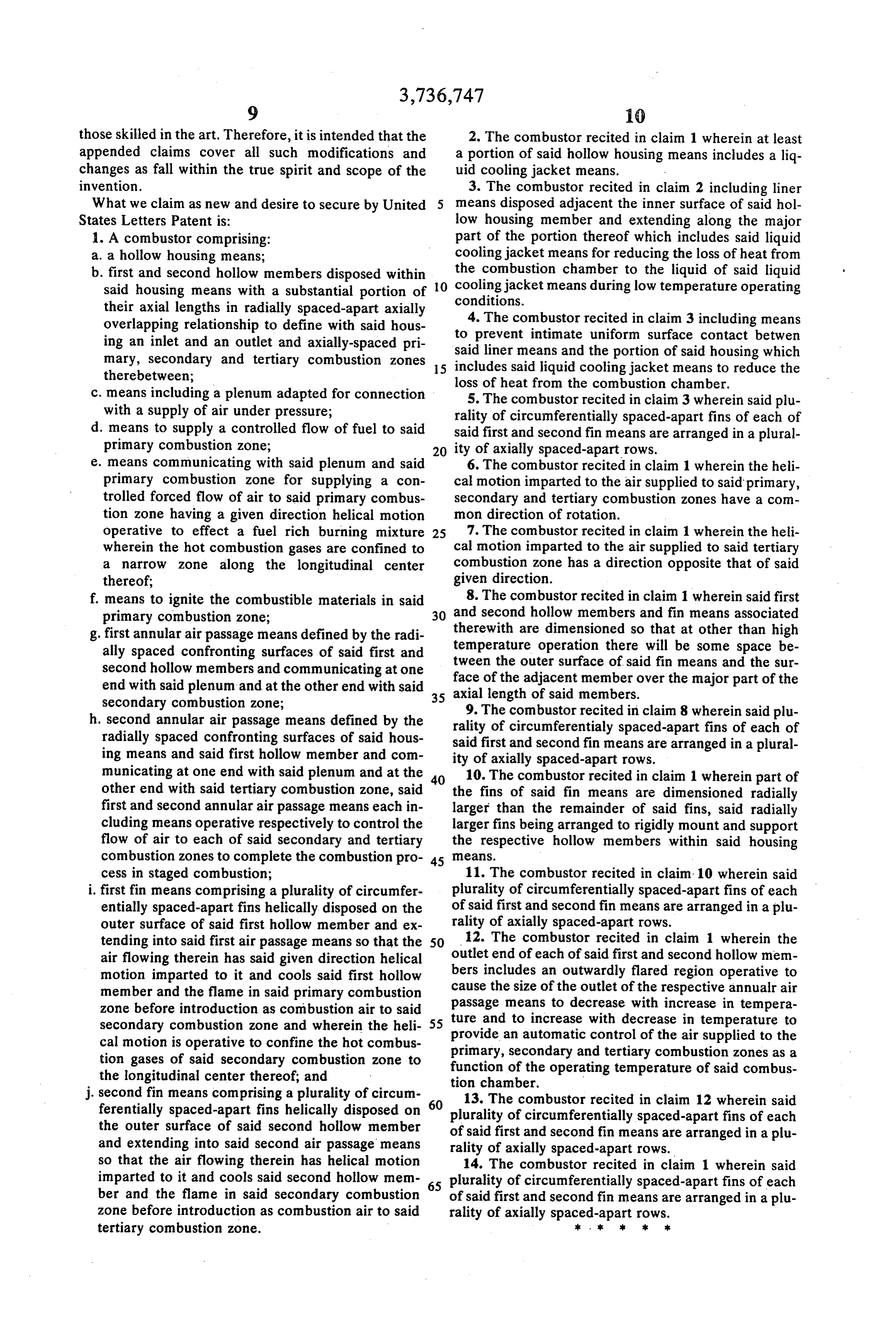
those skilled in the art. Therefore, it is intended that the 2. The combustor recited in claim 1 wherein at least appended claims cover all such modifications and a portion of said hollow housing means includes a liq changes as fall within the true spirit and scope of the uid cooling jacket means.
invention. 3. The combustor recited in claim 2 including liner What we claim as new and desire to secure by United 5 means disposed adjacent the inner surface of said hol States Letters Patent is: low housing member and extending along the major 1. A combustor comprising: part of the portion thereof which includes said liquid a. a hollow housing means; cooling jacket means for reducing the loss of heat from b. first and second hollow members disposed within the combustion chamber to the liquid of said liquid said housing means with a substantial portion of 0 cooling jacket means during low temperature operating their axial lengths in radially spaced-apart axially conditions.
overlapping relationship to define with said hous 4. The combustor recited in claim 3 including means ing an inlet and an outlet and axially-spaced pri to prevent intimate uniform surface contact betwen mary, secondary and tertiary combustion zones said liner means and the portion of said housing which includes said liquid cooling jacket means to reduce the therebetween; loss of heat from the combustion chamber. c. means including a plenum adapted for connection 5. The combustor recited in claim 3 wherein said plu with a supply of air under pressure; rality of circumferentially spaced-apart fins of each of d. means to supply a controlled flow of fuel to said said first and second fin means are arranged in a plural primary combustion zone; ity of axially spaced-apart rows. e. means communicating with said plenum and said 6. The combustor recited in claim 1 wherein the heli primary combustion zone for supplying a con cal motion imparted to the air supplied to said primary, trolled forced flow of air to said primary combus secondary and tertiary combustion zones have a com tion zone having a given direction helical motion mon direction of rotation.
operative to effect a fuel rich burning mixture 25 7. The combustor recited in claim 1 wherein the heli wherein the hot combustion gases are confined to cal motion imparted to the air supplied to said tertiary a narrow zone along the longitudinal center combustion zone has a direction opposite that of said thereof; given direction.
f. means to ignite the combustible materials in said and8. The combustor recited in claim 1 wherein said first second hollow members and fin means associated primary combustion zone;
g. first annular air passage means defined by the radi therewith temperature are dimensioned so that at other than high operation there will be some space be ally spaced confronting surfaces of said first and tween the outer surface of said fin means and the sur second hollow members and communicating at one face of the adjacent member over the major part of the end with said plenum and at the other end with said axial length of said members.
secondary combustion zone; 9. The combustor recited in claim 8 wherein said plu h, second annular air passage means defined by the rality of circumferentially spaced-apart fins of each of radially spaced confronting surfaces of said hous said first and second fin means are arranged in a plural ing means and said first hollow member and com ity of axially spaced-apart rows.
municating at one end with said plenum and at the 10. The combustor recited in claim 1 wherein part of other end with said tertiary combustion zone, said the fins of said fin means are dimensioned radially first and second annular air passage means each in larger than the remainder of said fins, said radially cluding means operative respectively to control the larger fins being arranged to rigidly mount and support flow of air to each of said secondary and tertiary the respective hollow members within said housing combustion zones to complete the combustion pro- 45 e3S.
cess in staged combustion; 11. The combustor recited in claim 10 wherein said i. first fin means comprising a plurality of circumfer plurality of circumferentially spaced-apart fins of each entially spaced-apart fins helically disposed on the of said first and second fin means are arranged in a plu outer surface of said first hollow member and ex rality of axially spaced-apart rows. 12. The combustor recited in claim 1 wherein the tending into said first air passage means so that the 50 outlet air flowing therein has said given direction helical end of each of said first and second hollow mem motion imparted to it and cools said first hollow bers includes an outwardly flared region operative to member and the flame in said primary combustion passage cause the size of the outlet of the respective annualr air zone before introduction as combustion air to said means to decrease with increase in tempera secondary combustion zone and wherein the heli- 55 provide antoautomatic ture and increase with decrease in temperature to cal motion is operative to confine the hot combus primary, secondary andcontrol of the air supplied to the tertiary combustion zones as a tion gases of said secondary combustion zone to function of the operating temperature of said combus the longitudinal center thereof; and tion chamber.
j. second fin means comprising a plurality of circum 13. The combustor recited in claim 12 wherein said ferentially spaced-apart fins helically disposed on plurality of circumferentially spaced-apart fins of each the outer surface of said second hollow member of said first and second fin means are arranged in a plu and extending into said second air passage means rality of axially spaced-apart rows.
so that the air flowing therein has helical motion 14. The combustor recited in claim 1 wherein said imparted to it and cools said second hollow mem plurality of circumferentially spaced-apart fins of each ber and the flame in said secondary combustion of said first and second fin means are arranged in a plu zone before introduction as combustion air to said rality of axially spaced-apart rows. tertiary combustion zone. . k is k ak
Provenance
- Collection
- Cited prior art
- Original PDF
- patentimages.storage.googleapis.com →
- Filed
- 1971-07-09
- Pages
- 9
- Method
- pdftotext (the PDF's own text layer) + pdftoppm 300dpi page scans
- Source
- Google Patents bibliographic record
- Granted
- 1973-06-05
- Inventors
- G Warren
- Transcribed from
- patentimages.storage.googleapis.com →