patent · US3645880
Electrode apparatus for brine electrolysis
29 February 1972
Page 1 — bibliographic record
Feb. 29, 1972 KENJ UEDA 3,645,880
ELECTRODE APPARATUS FOR BRINE ELECTROLYSIS
Filed May 14, l970 3. Sheets-Sheet (+) - - (-) FG 9 INVENTOR
by Oéco, A.A.e. £ Sauva-6
ATTORNEYS
Page 2
Drawing sheet — no readable text.
Page 3
Feb. 29, 1972 KENJJ UEDA 3,645,880
ELECTRODE APPARATUS FOR BRINE ELECTROLYSIS
Filed May 14, 1970 3. Sheets-Sheet 3
ias 80
0 - - - - - - - - - - , , ,
-- RATO OF THE LENGTH OF THE FIN IN THE EDGE OFA CATHODE
OPPOSING AN ANODE vs.THE DISTANCE BETWEENTHEELECTRODES (B/A)
DRVNG TIME (H)
NVENTOR
ATTORNEYS
Page 4
United States Patent Office 3,645,880 Patented Feb. 29, 1972
3,645,880 nesium hydroxide at the edge part thereof, the flow of ELECTRODE APPARATUS FOR BRINE brine in the flat, or central, part is also inhibited, and ELECTROLYSS the thickness of the deposition in this part also is in Kenji Ueda, Nagasaki, Japan, assignor to Mitsubishi creased. If such a phenomenon once occurs and pro Jukogyo Kabushiki Kaisha, Tokyo, Japan gresses, the flow between the electrodes becomes rapidly Filed May 14, 1970, Ser. No. 37,160 clogged and consequently the electrolytic cell cannot be Claims priority, application Japan, May 14, 1969, operated continuously.
44/37,256 SUMMARY OF THE INVENTION
U.S. C. 204-278 9 Claims O Accordingly, it is an object of the present invention to provide an improved electrode apparatus for use in
ABSTRACT OF THE DISCLOSURE
electrolyzing brine, or seawater, which may be operated continuously for a long period of time.
An apparatus for electrolyzing brine, or seawater, Another object of the present invention is to provide characterized by a cathode edge projection from the edge 5 an improved electrode apparatus for electrolyzing brine, of a parallel and opposite insoluble anode which is sub or Seawater, which may be operated continuously for a stantially five times greater than the distance between long period of time with little or no precipitative deposi these electrodes. The apparatus is immersed in a brine tion on the electrodes.
conducting passageway and current is applied thereto for Still another object of this invention is to provide an permitting electrolysis of the brine during continuous 20 improved electrode apparatus for preventing marine operation thereof, with little or no precipitative deposit on growth on parts contacted by a brine, or seawater electro the electrodes, and thereby providing uninterrupted flow lyte which is small in size and highly efficient, and cap of the brine through the passageway and the electrode able of a stable and prolonged operation without inhibit apparatus for preventing marine growth on parts con ing the flow rate of the brine between the electrodes. tacted by the brine. The foregoing and other objects are attained by an electrolytic cell for electrolyzing brine by applying cur rent between an insoluble anode and a cathode which
BACKGROUND OF THE INVENTION are immersed in the brine, characterized by the projec tion of an edge part of the cathode from the edge of
This invention relates generally to electrolytic cells 30 the parallel and oppositely disposed anode by more than and more particularly to an improved electrode apparatus five times the distance separating these electrodes. This which effectively prevents the adhesion of marine growth projection of the electroconductive edge of the cathode to parts immersed in brine, or seawater, by means of from the edge of the opposite anode equalizes the cur electrolysis products obtained during the continuous rent distribution on the cathode and thereby reduces any electrolysis of the brine over a long period of time. precipitative deposition on the cathode which normally It is well recognized that many problems are ordinarily restricts the flow of the seawater electrolyte through the caused by marine growth adhering to parts which nor cell.
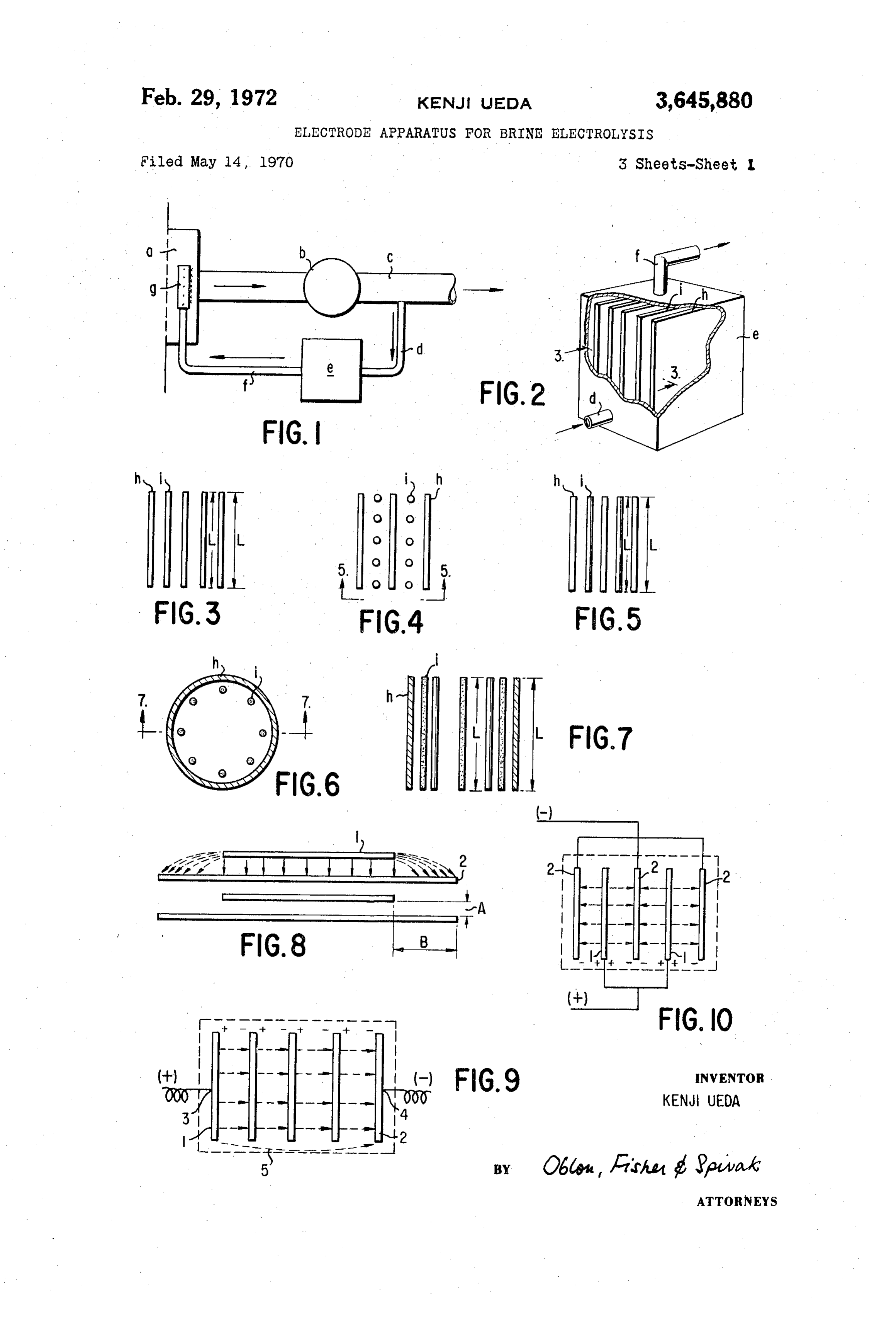
mally are maintained in contacting relationship with brine, or seawater, such as, for example, a brine intro BRIEF DESCRIPTION OF THE DRAWING(S) ducing duct of a ship or a steam power station, the 40 Other objects and many of the attendant features and draught part of a ship, a condenser which uses brine as advantages of the present invention will be readily appre a coolant, and the like. A common method for prevent ciated as the same becomes better understood from the ing the adhesion of marine growth to such parts involves following detailed description when considered in connec the use of a large capacity electrolytic cell disposed in tion with the accompanying drawings wherein like or the same brine atmosphere as are the parts for the pur corresponding parts are designated by like reference pose of producing and releasing chlorine compounds characters and in which:
therein. FIG. 1 is a schematic diagram showing a typical con Although this method enjoys wide use and is generally nection of an electrolytic cell in a system for preventing successful for its intended purpose, it has been found adhesion of marine growth to parts therein; that it is not always entirely satisfactory, especially where 50 FIG. 2 is a perspective view, partly in section, of a continuous operation for a long period of time is required. conventional parallel plate type electrolytic cell; It is well known, for example, that the current flowing FIG. 3 is a side view of FIG. 2 taken along the line between the electrodes of such cells usually is concen 3-3 therein;
trated at the edges thereof and that, during electrolysis FIG. 4 is a plan view of a conventional parallel plate in seawater, a precipitate of magnesium hydroxide, 55 bar type electrolytic cell;
Mg(OH)2, is generated at the cathode which effectively FIG. 5 is a side view of the device illustrated in FIG. reduces the flow rate of the brine, or seawater, passing 4 taken along the line 5-5 therein; between the electrodes. It has been found that in a part FIG. 6 is a horizontal sectional view of a conventional wherein the current density is flat, such as, for example, cylindrical type electrolytic cell; the central part of the electrode plate, magnesium hy 60 FIG. 7 is a side view, in longitudinal section, of the droxide precipitates constantly in equilibrium, having device illustrated in FIG. 6, taken along the line 7-7 some relation with the time, as well as the current density therein;
and the flow rate of the brine whereby, for example, FIG. 8 is a plan view of an electrode apparatus con when the flow rate is large, the thickness of the mag structed in accordance with the teachings of the present nesium hydroxide deposition is small. Also the current 65 invention;
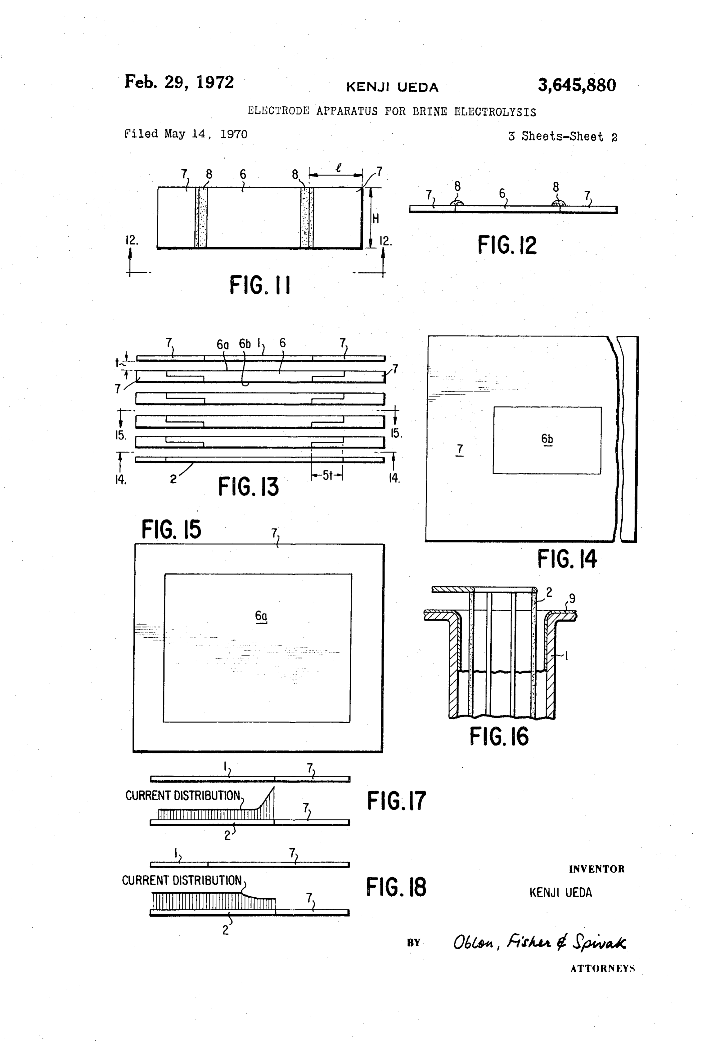
remarkedly concentrates at the edge of the cathode plate, FIG. 9 shows a typical connection of the electrodes of as herein above discussed, and the deposition of the mag an electrolytic cell in series relation; nesium hydroxide at the edges generally is several times FIG. 10 shows a typical connection of the electrodes as thick as in the flat, or central, part of the electrode of an electrolytic cell in parallel relation; late. 70 FIG. 11 is a plan view showing the precipitation of p Accordingly, if the flow rate of brine passing between magnesium hydroxide, Mg(OH)2, at the electrode with the electrodes is reduced by this deposition of the mag an insulating fin;
Page 5
FIG. 12 is a side view taken along the line 12-12 in plate and the flow rate of the brine, or seawater, passing FIG. 11; between the electrodes is thereby reduced. The flow of FIG. 13 is a plan view showing the arrangement of the brine in the flat part is also inhibited, and the thickness electrodes in a serially connected electrolytic cell and con of the magnesium hydroxide deposition in this part thus structed in accordance with the present invnetion; also becomes greater. This occurrence causes the flow FIG. 14 is a side view of the apparatus shown in FIG. between the electrodes to be rapidly clogged and conse 13 taken along the line 14-14 therein; quently the electrolytic cells heretofore used for this pur FIG. 15 is a side view of the apparatus illustrated in pose cannot be operated continuously for a long period FIG. 13 taken along the line 15-15 therein; of time.
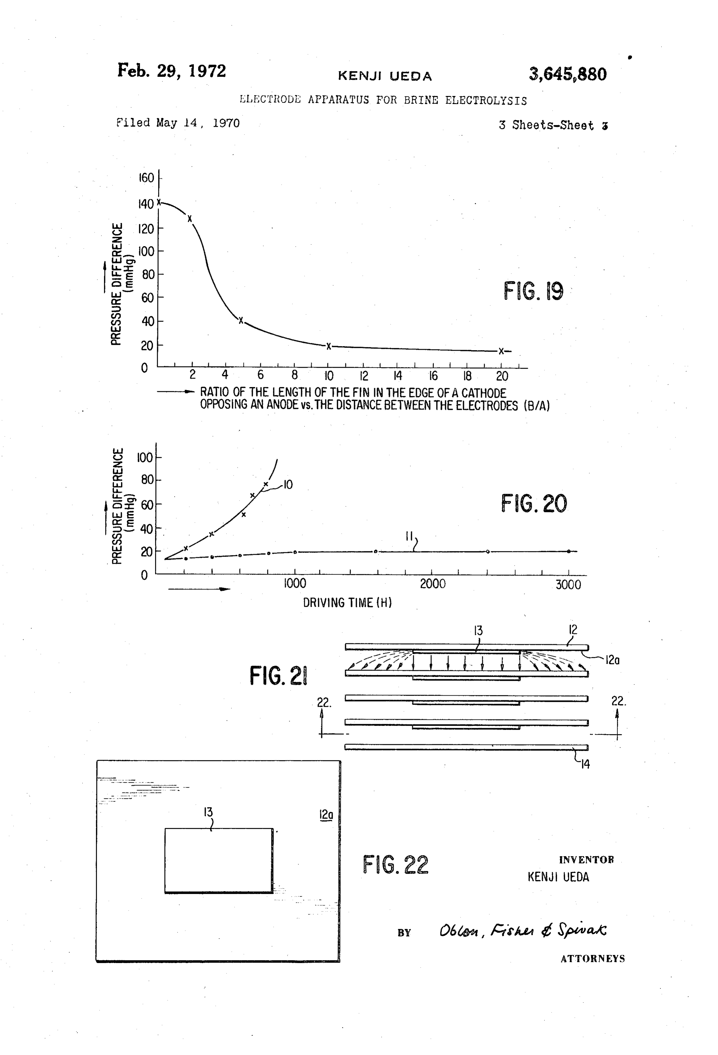
FIG. 16 is a longitudinal sectional view of another O Thus, the parallel plate type electrolytic cell, although embodiment of the present invention in a cylindrical type having such merits as being of small size and of good electrolytic cell; efficiency, is unreliable for long term, constant opera FIGS. 17 and 18 are comparative charts and show, tion. The parallel plate bar type and the cylindrical type respectively, the distribution of the current in an ordinary can be advantageously operated more constantly for a electrode and in an electrode constructed according to longer period of time, when compared to the parallel plate the present invention; type, but they are not yet satisfactory and are of larger FIG. 19 is a graph showing the static pressure difference SZ, between the inlet and the outlet of an electrolytic cell, In the electrolytic cell of the present invention, illus with a varying ratio of the length of the fin (B) along trated in FIG. 8, which has the advantages of being small the edge of a cathode opposing an anode versus the dis 20 in size and highly efficient, which were possessed by the tance (A) separating the electrodes, when brine is elec former parallel plate type electrolytic cells, but which trolyzed in a parallel plate type electrolytic cell provided does not share the disadvantage of becoming clogged be with the electrode apparatus of the present invention in cause of precipitative deposition on the electrodes and thus series connection; can provide stable and prolonged operation, an insoluble FIG. 20 is a graph showing the static pressure differ 25 anode 1, which may be constructed of such materials as ence between the inlet and the output of an electrode magnetic iron oxide, platinum, lead-silver alloy or plati apparatus having the ratio of the length (B) of the pro num plated titanium, and a cathode 2, which may be con jection in the cathode plate opposing the anode plate structed of iron or nickel, are placed opposite each other versus the distance (A) separating the electrode plates in predetermined spaced relation, and the electroconduc being 10 in that of an ordinary apparatus having a ratio 30 tive edge portion of the cathode 2, is provided with a fin of 0; B, which projects from the opposite of the edge of the FIG. 21 is a plan view showing another embodiment of anode 1 a distance substantially five or more times as the electrode apparatus of the present invention; and long as the predetermined distance A separating the elec FIG. 22 is a side view of the embodiment illustrated trodes.
in FIG. 21 taken along the arrow 22-22 therein. 35 A comparison will now be drawn between the present DESCRIPTION OF THE ILLUSTRATED invention and the parallel plate type electrolytic cells of EMBODIMENTS the prior art, shown in FIGS. 2 and 3. There are two ways of connecting a power source and the electrodes of a
Referring now to FIG. 1, there is shown a typical ar parallel plate type electrolytic cell, the serial connection rangement of an electrolytic cell in a system for prevent 40 thereof being shown in FIG. 9 and the parallel connec ing adhesion of marine growth on parts therein which tion being shown in FIG. 10. Since low current and high normally contact the brine, or seawater, wherein the brine Voltage are desirable from the economic standpoint as to is drawn through an inlet a by a brine pump b and in consideration of the power source, the electrodes are most troduced to the system through a brine channel c, and a often connected in series.
brine introduction channel d is designed to divert part 45 In Serial connection, as shown in FIG. 9, the voltage of the brine from the channel c to an electrolytic cell e of large capacity. An electrolytic product consisting of difference between the input terminal 3 and the outputter minal 4 is quite large and results in a large by-pass, or chlorine compounds is formed in the cell e and is di Stray, Current. In addition, increase of the current has rected therefrom through a chlorine-containing brine chan been found to have no relation with the results of the nel f to a nozzle g disposed adjacent the brine inlet a 50 electrolysis procedure so far as causing a reduction of for distribution therein, whereby the part which must be the current efficiency. According to a study and experi kept free of adhering marine growth is placed in an mentation, the stray current may be represented by the atmosphere of the chlorine-containing electrolytic product following formulae:
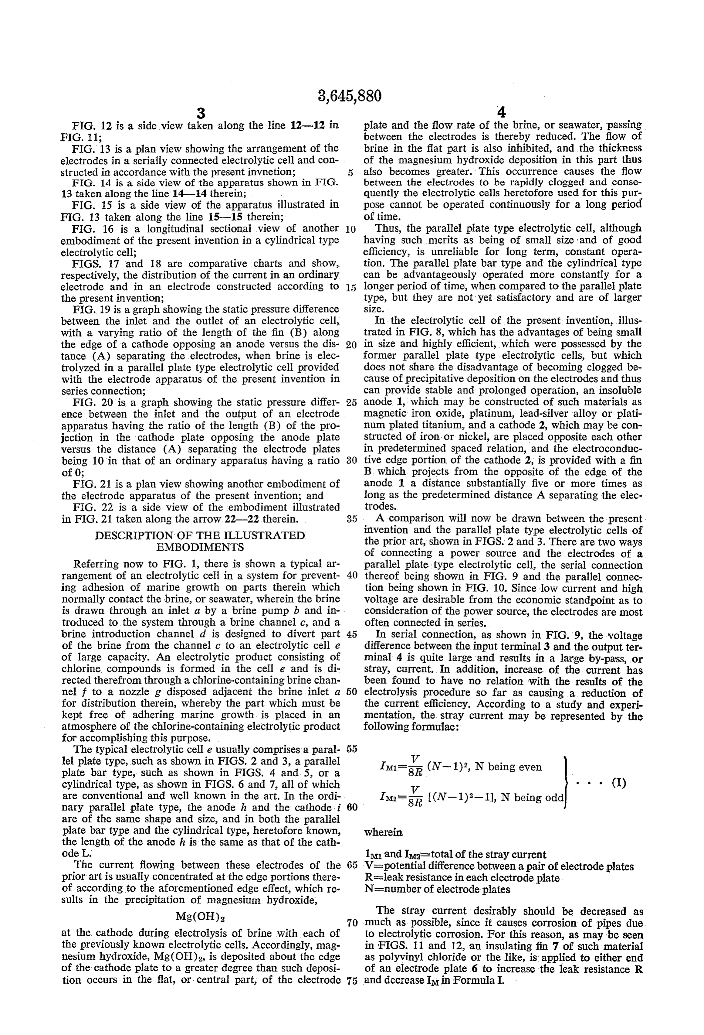
for accomplishing this purpose.
The typical electrolytic celle usually comprises a paral 55 y lel plate type, such as shown in FIGS. 2 and 3, a parallel IM1-5 (N-1)2, N being even plate bar type, such as shown in FIGS. 4 and 5, or a cylindrical type, as shown in FIGS. 6 and 7, all of which y . . . (I) are conventional and well known in the art. In the ordi IM2- I(N-1)2-1), N being odd nary parallel plate type, the anode h and the cathodei 60 are of the same shape and size, and in both the parallel plate bar type and the cylindrical type, heretofore known, wherein the length of the anode h is the same as that of the cath ode L. 1M1 and Ma-total of the stray current The current flowing between these electrodes of the 65 V=potential difference between a pair of electrode plates prior art is usually concentrated at the edge portions there R=leak resistance in each electrode plate of according to the aforementioned edge effect, which re N=number of electrode plates sults in the precipitation of magnesium hydroxide,
The stray current desirably should be decreased as 70 much as possible, since it causes corrosion of pipes due at the cathode during electrolysis of brine with each of to electrolytic corrosion. For this reason, as may be seen the previously known electrolytic cells. Accordingly, mag in FIGS. 11 and 12, an insulating fin 7 of such material nesium hydroxide, Mg(OH)2, is deposited about the edge as polyvinyl chloride or the like, is applied to either end of the cathode plate to a greater degree than such deposi of an electrode plate 6 to increase the leak resistance R tion occurs in the flat, or central part, of the electrode 75 and decrease IM in Formula I.
Page 6
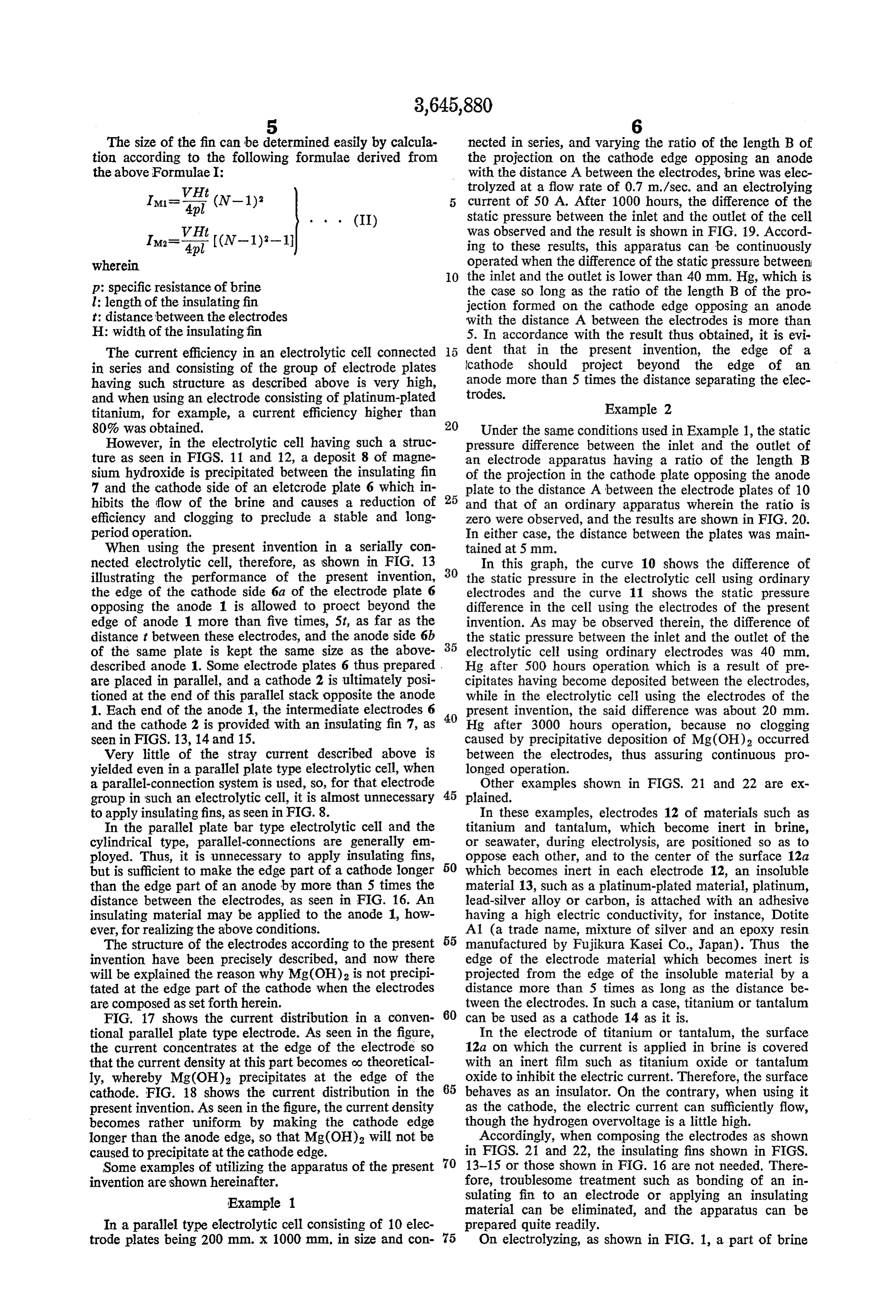
The size of the fin can be determined easily by calcula nected in series, and varying the ratio of the length B of tion according to the following formulae derived from the projection on the cathode edge opposing an anode the above Formulae I: with the distance A between the electrodes, brine was elec trolyzed at a flow rate of 0.7 m./sec. and an electrolying
Isa-E (N-1)2 5 current of 50 A. After 1000 hours, the difference of the static pressure between the inlet and the outlet of the cell
VH (II) was observed and the result is shown in FIG. 19. Accord Ima-, (N-1)-1 ing to these results, this apparatus can be continuously wherein operated when the difference of the static pressure between O the inlet and the outlet is lower than 40 mm. Hg, which is p: specific resistance of brine the case so long as the ratio of the length B of the pro l: length of the insulating fin jection formed on the cathode edge opposing an anode t: distance between the electrodes with the distance A between the electrodes is more than H: width of the insulatingfin 5. In accordance with the result thus obtained, it is evi The current efficiency in an electrolytic cell connected dent that in the present invention, the edge of a in series and consisting of the group of electrode plates cathode should project beyond the edge of an having such structure as described above is very high, anode more than 5 times the distance separating the elec and when using an electrode consisting of platinum-plated trodes.
titanium, for example, a current efficiency higher than Example 2 80% was obtained. 20 Under the same conditions used in Example 1, the static However, in the electrolytic cell having such a struc pressure difference between the inlet and the outlet of ture as seen in FIGS. 11 and 12, a deposit 8 of magne an electrode apparatus having a ratio of the length B sium hydroxide is precipitated between the insulating fin of the projection in the cathode plate opposing the anode 7 and the cathode side of an eletcrode plate 6 which in 25 plate to the distance A between the electrode plates of 10 hibits the flow of the brine and causes a reduction of and that of an ordinary apparatus wherein the ratio is efficiency and clogging to preclude a stable and long zero were observed, and the results are shown in FIG. 20. period operation. In either case, the distance between the plates was main When using the present invention in a serially con tained at 5 mm.
nected electrolytic cell, therefore, as shown in FIG. 13 30 In this graph, the curve 10 shows the difference of illustrating the performance of the present invention, the static pressure in the electrolytic cell using ordinary the edge of the cathode side 6a of the electrode plate 6 electrodes and the curve 11 shows the static pressure opposing the anode 1 is allowed to proect beyond the difference in the cell using the electrodes of the present edge of anode 1 more than five times, 5t, as far as the invention. As may be observed therein, the difference of distance t between these electrodes, and the anode side 6b 35 the static pressure between the inlet and the outlet of the of the same plate is kept the same size as the above electrolytic cell using ordinary electrodes was 40 mm. described anode 1. Some electrode plates 6 thus prepared Hg after 500 hours operation which is a result of pre are placed in parallel, and a cathode 2 is ultimately posi cipitates having become deposited between the electrodes, tioned at the end of this parallel stack opposite the anode while in the electrolytic cell using the electrodes of the 1. Each end of the anode 1, the intermediate electrodes 6 40 present invention, the said difference was about 20 mm. and the cathode 2 is provided with an insulating fin 7, as Hg after 3000 hours operation, because no clogging seen in FIGS. 13, 14 and 15. caused by precipitative deposition of Mg(OH)2 occurred Very little of the stray current described above is between the electrodes, thus assuring continuous pro yielded even in a parallel plate type electrolytic cell, when longed operation.
a parallel-connection system is used, so, for that electrode Other examples shown in FIGS. 21 and 22 are ex group in such an electrolytic cell, it is almost unnecessary 45 plained.
to apply insulating fins, as seen in FIG. 8. In these examples, electrodes 12 of materials such as In the parallel plate bar type electrolytic cell and the titanium and tantalum, which become inert in brine, cylindrical type, parallel-connections are generally em or seawater, during electrolysis, are positioned so as to ployed. Thus, it is unnecessary to apply insulating fins, oppose each other, and to the center of the surface 12a but is sufficient to make the edge part of a cathode longer 50 which becomes inert in each electrode 12, an insoluble than the edge part of an anode by more than 5 times the material 13, such as a platinum-plated material, platinum, distance between the electrodes, as seen in FIG. 16. An lead-silver alloy or carbon, is attached with an adhesive insulating material may be applied to the anode 1, how having a high electric conductivity, for instance, Dotite ever, for realizing the above conditions. A1 (a trade name, mixture of silver and an epoxy resin The structure of the electrodes according to the present 55 manufactured by Fujikura Kasei Co., Japan). Thus the invention have been precisely described, and now there edge of the electrode material which becomes inert is will be explained the reason why Mg(OH)2 is not precipi projected from the edge of the insoluble material by a tated at the edge part of the cathode when the electrodes distance more than 5 times as long as the distance be are composed as set forth herein. tween the electrodes. In such a case, titanium or tantalum FIG. 17 shows the current distribution in a conven 60 can be used as a cathode 14 as it is.
tional parallel plate type electrode. As seen in the figure, In the electrode of titanium or tantalun, the surface the current concentrates at the edge of the electrode so 12a on which the current is applied in brine is covered that the current density at this part becomes oo theoretical with an inert film such as titanium oxide or tantalum ly, whereby Mg(OH)2 precipitates at the edge of the oxide to inhibit the electric current. Therefore, the surface cathode. FIG. 18 shows the current distribution in the 65 behaves as an insulator. On the contrary, when using it present invention. As seen in the figure, the current density as the cathode, the electric current can sufficiently flow, becomes rather uniform by making the cathode edge though the hydrogen overvoltage is a little high. longer than the anode edge, so that Mg(OH)2 will not be Accordingly, when composing the electrodes as shown caused to precipitate at the cathode edge. in FIGS. 21 and 22, the insulating fins shown in FIGS. Some examples of utilizing the apparatus of the present O 13-15 or those shown in FIG. 16 are not needed. There invention are shown hereinafter. fore, troublesome treatment such as bonding of an in Example 1 sulating fin to an electrode or applying an insulating material can be eliminated, and the apparatus can be
In a parallel type electrolytic cell consisting of 10 elec prepared quite readily.
trode plates being 200 mm. X 1000 mm. in size and con 75 On electrolyzing, as shown in FIG. 1, a part of brine
Page 7
is introduced from the brine channel c to an electrolytic 3. The apparatus set forth in claim 1 wherein said celle through a brine introducing duct d, and the elec cathode is composed of iron.
trolytic cell may be provided with the electrode apparatus 4. The apparatus set forth in claim 1 wherein said of the present invention shown in FIGS. 13-15. Thus, a cathode is composed of nickel. chlorine gas generates from the insoluble anode 1, 6b and 5 5. An apparatus for electrolyzing brine characterized a hydrogen gas generates from the cathode 2, 6a, and the by applying current to at least a pair of spaced electrodes former dissolves in brine to afford chlorine compounds, which are immersed in brine and positioned so as to which are introduced to the brine inlet a through the oppose each other, the improvement comprising an elec chlorine-containing brine duct f. trode apparatus characterized by an electrode which is In the electrode apparatus according to the present 10 composed of a material which becomes inert in brine and invention as the edge of the cathode is projected beyond has an insoluble material bonded to a central part of the the edge of the opposite anode more than 5 times the inert surface, and the edge of the said inert material distance between the electrodes, precipitation of surface projecting beyond the edge of said insoluble ma Mg(OH)2, which previously has been deposited at the edge of the cathode, is hardly observed, and consequently, 5 terial bonded thereto at least 5 times as far as the distance clogging between the electrodes can be prevented. Thus, separating the same from the next adjacent electrode. the electrolytic cell for brine can be advantageously op 6. The apparatus set forth in claim S wherein said inert erated constantly for a long period of time. material is titanium.
Particularly, adopting the electrode apparatus of the 7. The apparatus set forth in claim 5 wherein said inert present invention to a serially connected parallel plate material is tantalum.
type electrolytic cell, the cell can be made compact and 8. The apparatus set forth in claim 5 wherein said in highly efficient. soluble material is one from a group consisting of Obviously, many modifications and variations of the platinum, a platinum-plated material, a lead-silver alloy present invention are possible in light of the above teach and carbon.
ings. It is understood, therefore, that within the scope of the appended claims, the invention may be practiced 9. The apparatus set forth in claim 5 wherein said otherwise than as specifically described. insoluble material is bonded to said inert material elec What is claimed is: trode with a highly electrically conductive adhesive. 1. An apparatus for electrolyzing brine characterized References Cited by applying current to an insoluble anode and a cathode 30 which are immersed in the brine and positioned so as to UNITED STATES PATENTS oppose each other in predetermined spaced relation, the 3,458 414 7/1969 Crane et al. -------- 204-149 improvement comprising an electrode apparatus charac 3,530,051 9/1970 Ueda et al. -------- 204-149 terized by the electroconductive edge of said cathode pro jecting beyond the edge of said opposite anode at least 5 times as far as the distance separating said electrodes. JOHN H. MACK, Primary Examiner 2. The apparatus set forth in claim 1 wherein said W. E. SOLOMON, Assistant Examiner insoluble anode is composed of a material from the group consisting of magnetic iron oxide, platinum, a lead-silver U.S. C. X.R. alloy and platinum-plated titanium. 40 204-258, 270
Provenance
- Collection
- Cited prior art
- Original PDF
- patentimages.storage.googleapis.com →
- Filed
- 1970-05-14
- Pages
- 7
- Method
- pdftotext (the PDF's own text layer) + pdftoppm 300dpi page scans
- Source
- Google Patents bibliographic record
- Granted
- 1972-02-29
- Inventors
- Kenji Ueda; Mitsubishi Heavy Industries Ltd
- Transcribed from
- patentimages.storage.googleapis.com →