patent · US3496871
Energy conversion device
24 February 1970
Page 1
Drawing sheet — no readable text.
Page 2
Drawing sheet — no readable text.
Page 3
Drawing sheet — no readable text.
Page 4
United States Patent Office 3,496,87: Patented Feb. 24, 1970
3,496,871 bient pressure into the hollow pipe through the inlet port, ENERGY CONVERSION DEVICE whereby the fluid propels each magnetic piston to orbit Linda Folkard Stengel, Los Angeles, Calif., assignor to in the hollow pipe to thereby induce electric current in. Entropy Limited, Toronto, Ontario, Canada, a corpora the coil windings.
tion of Canada The method of operating the novel energy conversion Fied Sept. 13, 1967, Ser. No. 667,592 device as a pump for fluids comprises introducing a fluid int. C. F04b. 19/00, H02k 41/00 at ambient pressure into the hollow pipe and then pass U.S. C. 103-1 10 Claims ing an electric current through the coil windings, where by the magnetic field induced in the coil windings by the
O electric current serves to propel the magnetic pistons and
ABSTRACT OF THE DISCLOSURE to thereby circulate the fluid from the intake port to the A generator or pump comprising a coil wound toroidal outlet port.
pipe with inlet and outlet ports and having at least two In the generator mode the fluid used may be a cold permanently magnetized pistons located within and free gas, a hot gas, or a liquid. In the pump mode, the fluid to orbit around the pipe. The passage of fluid through the 5 pumped may be liquid or gaseous. pipe propels the magnetic piston or pistons to orbit within In the generator mode, fluid (liquid or gaseous) enters the toroidal pipe, thereby inducing electric current in the the device through the inlet port at a velocity c greater surrounding coils, while alternatively the passage of elec than the velocity u at which the magnetic pistons orbit tric current through said coils propels the magnetic. pis within the hollow pipe. This results. in an energy transfer ton or pistons to orbit within the toroidal pipe thereby 20. proportional to (c-u)u from the fluid to the magnetic inducing circulation of the liquid through said pipe. pistons. By inductive coupling between the magnetic pis ton fields and the coil windings, the orbiting motion of the magnetic pistons induces, alternating current in the
BACKGROUND OF THE INVENTION coil windings. The fluid leaves the outlet port after one 25 orbit, while each magnetic piston continues in its path
This invention relates to an energy conversion device about the torus. - for selectively converting fluid pressure energy into elec In the pump mode, alternating current (preferably, but trical energy and for converting electrical energy into fluid not strictly necessarily, 3-phase) is supplied to the coil pressure energy, such as in generators, pumps and the windings to generate an orbiting electromagnetic field like. This invention further relates to energy conversion 30 and thereby to inductively cause the magnetic pistons to devices for converting one form of electrical energy to orbit within the hollow toroidal shaped pipe. Fluid (liq another form of electric energy, such as for the conver uid or gaseous) is entrained at the intake port between sion of D.C. current energy to A.C. current energy. orbiting magnetic pistons and is discharged at the outlet DESCRIPTION OF THE INVENTION port, thereby effecting fluid transfer through the hollow 35 pipe.
The energy conversion device of the present in The following examples serve to illustrate some em. vention comprises a hollow tubular pipe of circular form bodiments of the novel device in the generator mode. in plane to provide an endless cylindrical closed circuit, EXAMPLE 1. at least two pistons of permanently magnetised metal 40 are mounted in the tubular pipe for free orbit therein. The novel device of this invention may be inserted The magnetic poles of the pistons are aligned coaxially between the exhaust manifold and the exhaust muffler of and oriented to have like poles facing each other. The an otherwise conventional internal combustion engine tubular pipe has fluid inlet and outlet ports through which (diesel or gasoline, 4-stroke or 2-stroke and the like), fluid is admitted to and from the cylinder and energizable 45 and serves then to replace the conventional generator or coil windings surrounding at least a part of the tubular alternator. (This application is described hereinafter as pipes. a specific embodiment of the invention.) The hollow pipe may be formed into any shape which in conventional unsupercharged internal combustion defines a closed circuit for the orbiting motion of the phase engines, the energy of the exhaust gases in the blowdown magnetic piston means and which encompasses no abrupt (cylinder pressure appreciably above atmospheric bends in the pipe which could interfere with the orbiting 50 purpose pressure) is not utilized ard is therefore wasted. The of using a device according to the present inven motion of the magnetic piston means. While many con figurations of hollow pipe (e.g. toroidal, helical with the tion is to extract at least a portion of this blowdown ends joined, and the like) may be used, the circular ring energy and convert it into useful electric energy. The shaped configuration is preferred. advantages are then twofold (assuming proper design, 55 so that no additional back pressure on the engine is
The magnetic piston means consists of at least one created). First, the device replaces the conventional gen magnetic piston. It is preferable that each such magnetic erator or alternator, both of which are belt-driven in a piston be cylindrical in form and with opposite poles on typical engine; this saves engine power and cost. Second, opposite ends of each cylinder. For efficient operation the magnetic pistons should be of sufficiently large cross-sec 60 since the device extracts energy from the exhaust gas, tion to effect good sealing with the inner surface of the it(less also makes possible the use of a smaller exhaust muffler weight, volume and cost) while still complying hollow pipe against the leakage of fluid. When two or with noise limit regulations. more magnetic pistons are used the pistons are oriented to have like poles face each other which maintains the EXAMPLE 2 pistons in spaced apart relationship. The device may be used in conjunction with a com The novel device of this invention has two distinct presssed-gas source (compressed air bottle or solid-fuel modes of operation. hot-gas generator cartridge) as an intermittent source The method of operating the energy conversion device. . of electric power.
of this invention as a generator of electricity comprises In areas removed from an accessible electric power maintaining the operating temperatures below the Curie 70 line, electric energy may be needed at low power levels temperature for the material of the magnetic pistons, and and for short periods of time only (example: emergency introducing the fluid at a pressure greater than the am i radio set). As an illustrative case, the energy retrievable
Page 5
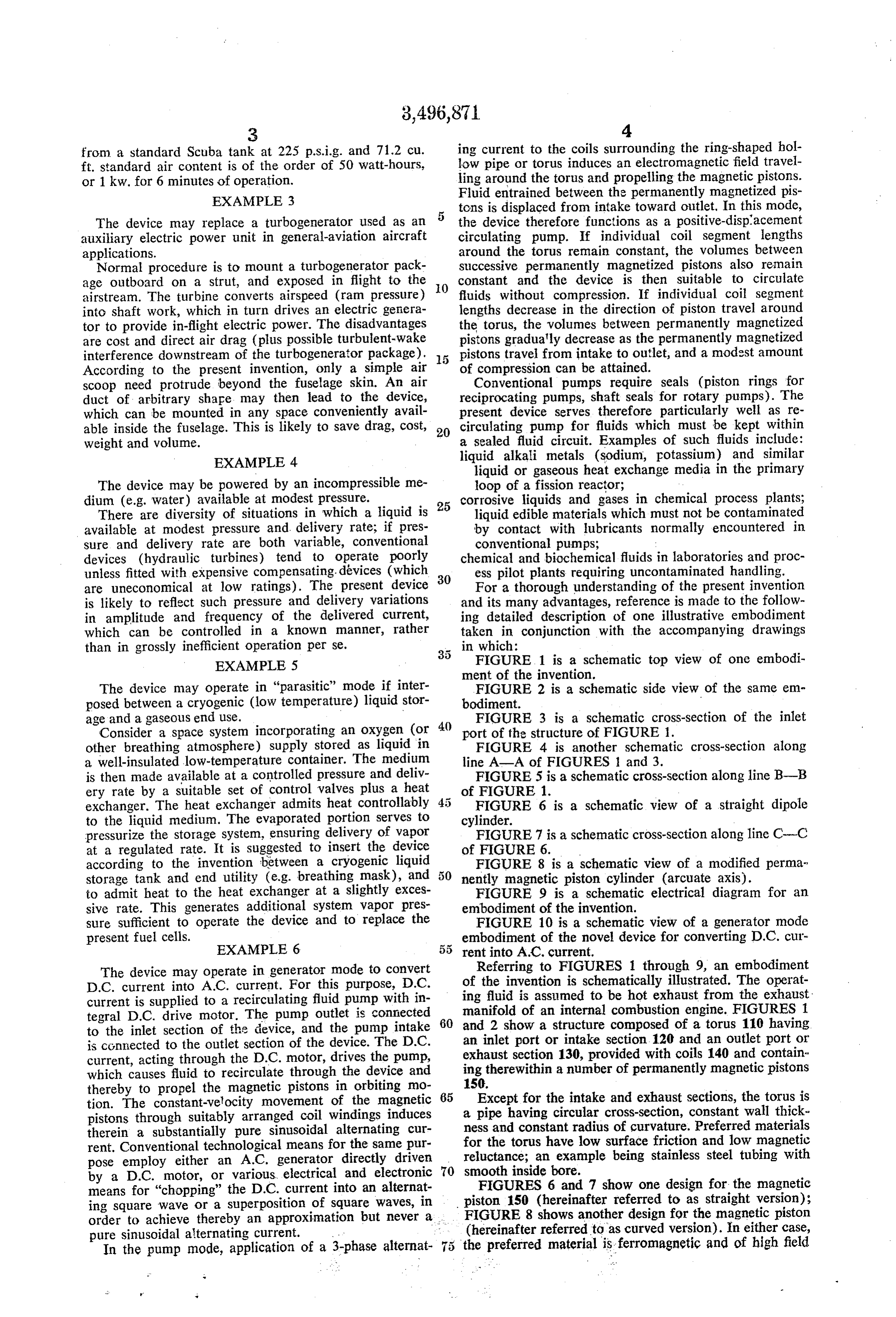
from a standard Scuba tank at 225 p.s.i.g. and 71.2 cu. ing current to the coils surrounding the ring-shaped hol ft. standard air content is of the order of 50 watt-hours, low pipe or torus induces an electromagnetic field travel or 1 kw. for 6 minutes of operation. ling around the torus and propelling the magnetic pistons.
EXAMPLE 3
Fluid entrained between the permanently magnetized pis tons is displaced from intake toward outlet. In this mode,
The device may replace a turbogenerator used as an 5 the device therefore functions as a positive-displacement auxiliary electric power unit in general-aviation aircraft circulating pump. If individual coil segment lengths applications. around the torus remain constant, the volumes between Normal procedure is to mount a turbogenerator pack Successive permanently magnetized pistons also remain age outboard on a strut, and exposed in flight to the 0. constant and the device is then suitable to circulate airstream. The turbine converts airspeed (ram pressure) fluids without compression. If individual coil segment into shaft work, which in turn drives an electric genera lengths decrease in the direction of piston travel around tor to provide in-flight electric power. The disadvantages the torus, the volumes between permanently magnetized are cost and direct air drag (plus possible turbulent-wake pistons gradually decrease as the permanently magnetized interference downstream of the turbogenerator package). pistons travel from intake to outlet, and a modest amount According to the present invention, only a simple air of compression can be attained. scoop need protrude beyond the fuselage skin. An air Conventional pumps require seals (piston rings for duct of arbitrary shape may then lead to the device, reciprocating pumps, shaft seals for rotary pumps). The which can be mounted in any space conveniently avail present device serves therefore particularly well as re able inside the fuselage. This is likely to save drag, cost, 20 circulating pump for fluids which must be kept within weight and volume. a sealed fluid circuit. Examples of such fluids include: EXAMPLE 4 liquid alkali metals (sodium, potassium) and similar liquid or gaseous heat exchange media in the primary
The device may be powered by an incompressible me loop of a fission reactor;
dium (e.g. water) available at modest pressure. corrosive liquids and gases in chemical process plants; There are diversity of situations in which a liquid is 25 liquid edible materials which must not be contaminated available at modest pressure and delivery rate; if pres by contact with lubricants normally encountered in sure and delivery rate are both variable, conventional conventional pumps;
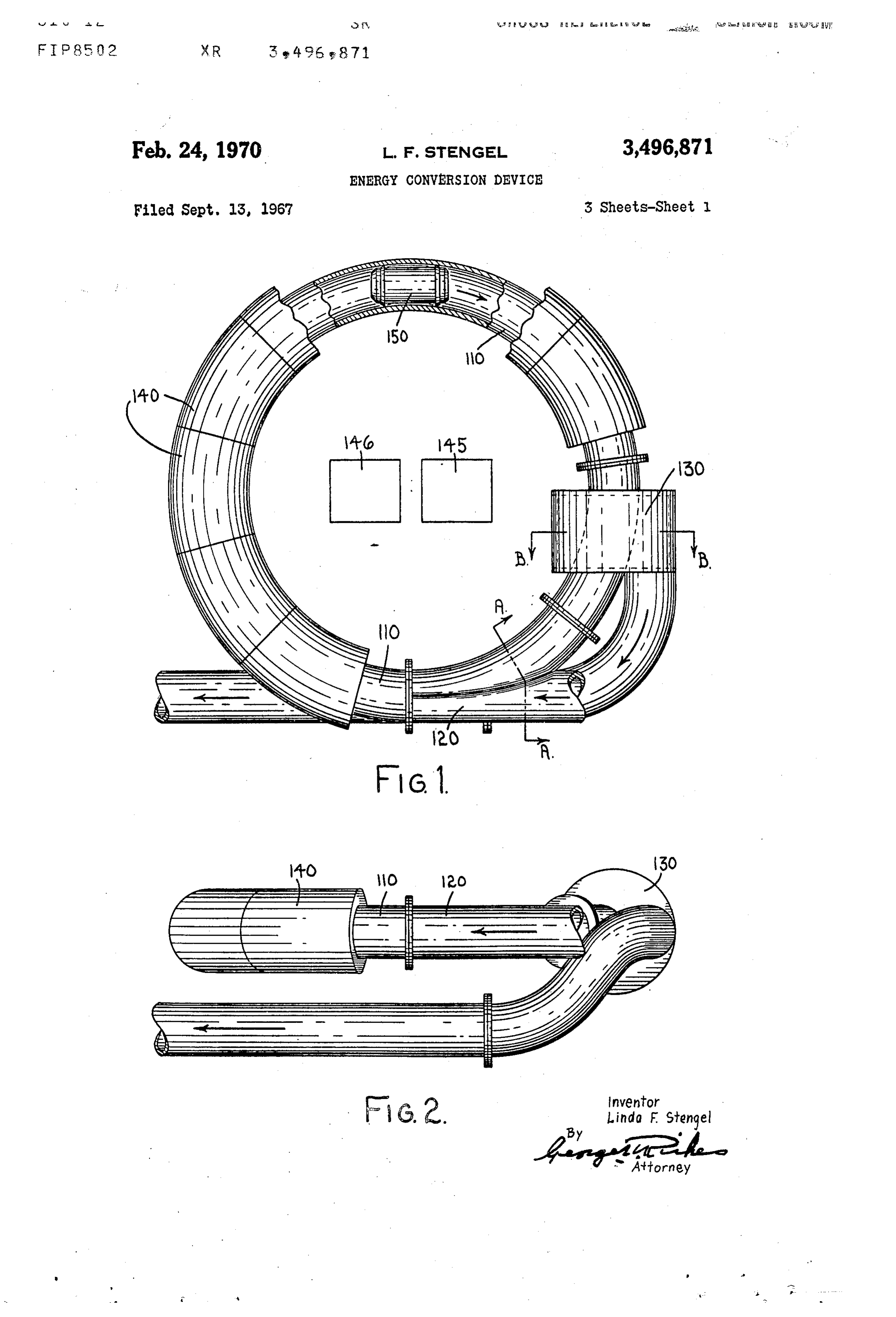
devices (hydraulic turbines) tend to operate poorly chemical and biochemical fluids in laboratories and proc unless fitted with expensive compensating. devices (which 30 ess pilot plants requiring uncontaminated handling. are uneconomical at low ratings). The present device For a thorough understanding of the present invention is likely to reflect such pressure and delivery variations and its many advantages, reference is made to the follow in amplitude and frequency of the delivered current, ing detailed description of one illustrative embodiment which can be controlled in a known manner, rather taken in conjunction with the accompanying drawings than in grossly inefficient operation per se. in which:
EXAMPLE 5 FIGURE 1 is a schematic top view of one embodi ment of the invention.
The device may operate in "parasitic' mode if inter FIGURE 2 is a schematic side view of the same em posed between a cryogenic (low temperature) liquid stor bodiment.
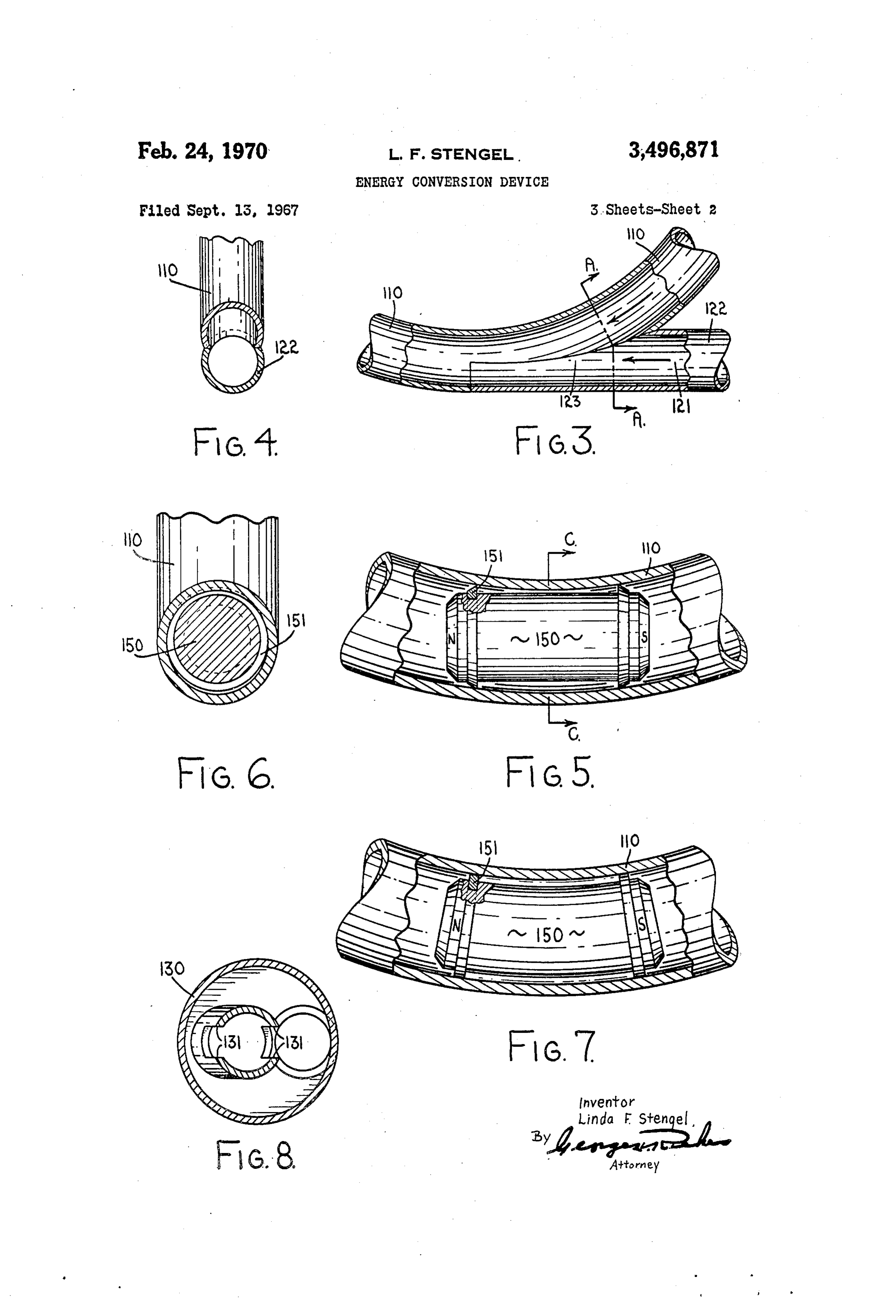
age and a gaseous end use. FIGURE 3 is a schematic cross-section of the inlet Consider a space system incorporating an oxygen (or 40 port of the structure of FIGURE 1.
other breathing atmosphere) supply stored as liquid in FIGURE 4 is another schematic cross-section along a well-insulated low-temperature container. The medium line A-A of FIGURES 1 and 3.
is then made available at a controlled pressure and deliv FIGURE 5 is a schematic cross-section along line B-B ery rate by a suitable set of control valves plus a heat of FIGURE 1.
exchanger. The heat exchanger admits heat controllably FIGURE 6 is a schematic view of a straight dipole to the liquid medium. The evaporated portion serves to cylinder.
pressurize the storage system, ensuring delivery of vapor FIGURE 7 is a schematic cross-section along line C-C at a regulated rate. It is suggested to insert the device of FIGURE 6.
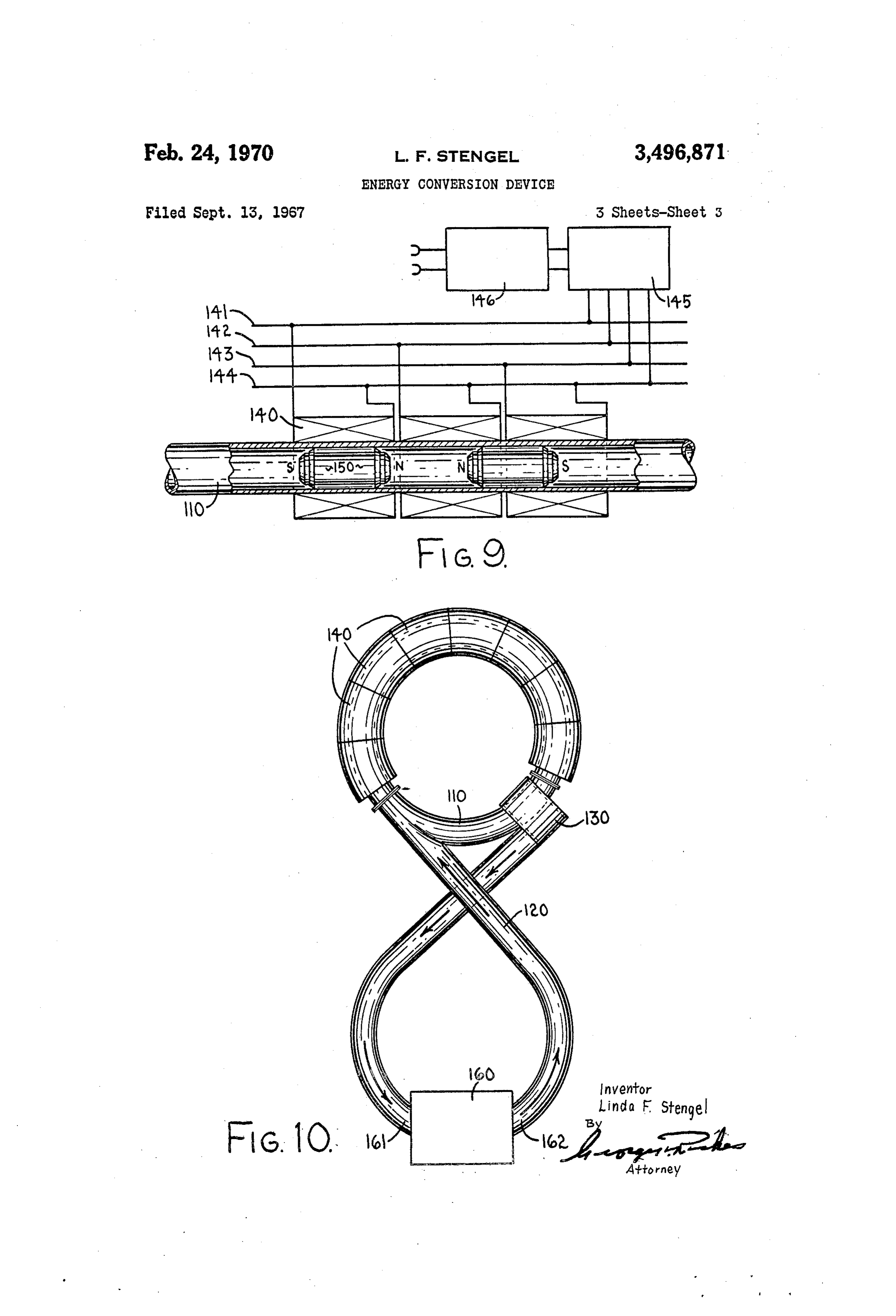
according to the invention between a cryogenic liquid FIGURE 8 is a schematic view of a modified perma storage tank and end utility (e.g. breathing mask), and nently magnetic piston cylinder (arcuate axis). to admit heat to the heat exchanger at a slightly exces FIGURE 9 is a schematic electrical diagram for an sive rate. This generates additional system vapor pres embodiment of the invention.
sure sufficient to operate the device and to replace the FIGURE 10 is a schematic view of a generator mode present fuel cells. embodiment of the novel device for converting D.C. cur EXAMPLE 6 rent into A.C. current.
The device may operate in generator mode to convert of Referring to FIGURES 1 through 9, an embodiment the invention is schematically illustrated. The operat
D.C. current into A.C. current. For this purpose, D.C.
current is supplied to a recirculating fluid pump with in ing fluid is assumed to be hot exhaust from the exhaust tegral D.C. drive motor. The pump outlet is connected 60 manifold of an internal combustion engine. FIGURES 1 and 2 show a structure composed of a torus 110 having to the inlet section of the device, and the pump intake is connected to the outlet section of the device. The D.C. an inlet port or intake section 120 and an outlet port or current, acting through the D.C. motor, drives the pump, exhaust section 130, provided with coils 140 and contain which causes fluid to recirculate through the device and ing therewithin a number of permanently magnetic pistons thereby to propel the magnetic pistons in orbiting mo 65 150.
tion. The constant-velocity movement of the magnetic Except for the intake and exhaust sections, the torus is pistons through suitably arranged coil windings induces aness pipe having circular cross-section, constant wall thick and constant radius of curvature. Preferred materials therein a substantially pure sinusoidal alternating cur rent. Conventional technological means for the same pur for the torus have low surface friction and low magnetic pose employ either an A.C. generator directly driven reluctance; an example being stainless steel tubing with by a D.C. motor, or various. electrical and electronic 70 smooth inside bore.
FIGURES 6 and 7 show one design for the magnetic means for “chopping” the D.C. current into an alternat piston 150 (hereinafter referred to as straight version); ing square wave or a superposition of square waves, in order to achieve thereby an approximation but never a FIGURE 8 shows another design for the magnetic piston (hereinafter referred to as curved version). In either case, pureIn sinusoidal alternating current.
the pump mode, application of a 3-phase alternat the preferred material is ferromagnetic and of high field
Page 6
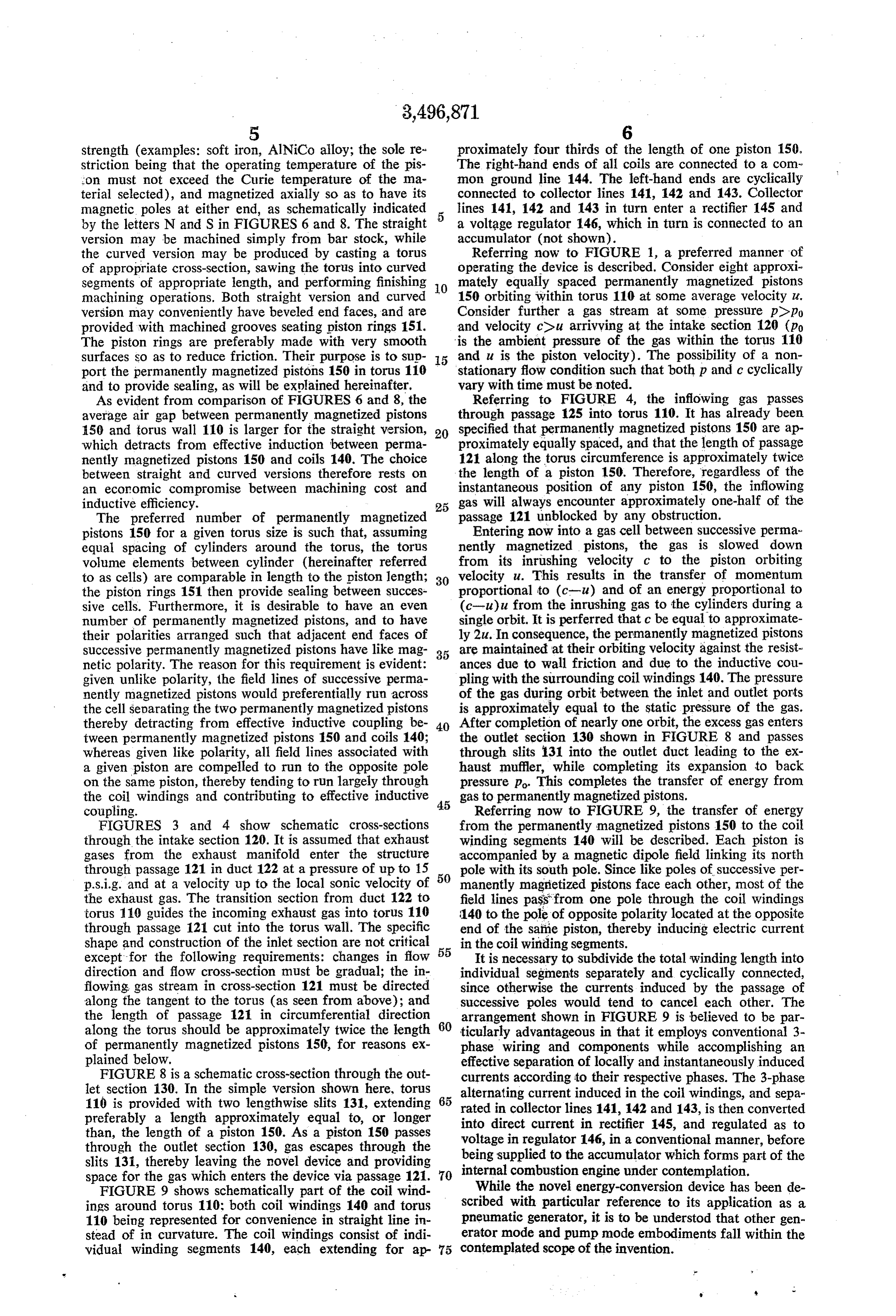
strength (examples: soft iron, AlNiCo alloy; the sole re proximately four thirds of the length of one piston 150. striction being that the operating temperature of the pis The right-hand ends of all coils are connected to a com on must not exceed the Curie temperature of the ma mon ground line 144. The left-hand ends are cyclically terial selected), and magnetized axially so as to have its connected to collector lines 141, 142 and 143. Collector magnetic poles at either end, as schematically indicated lines 141, 142 and 143 in turn enter a rectifier 145 and by the letters N and S in FIGURES 6 and 8. The straight a voltage regulator 146, which in turn is connected to an version may be machined simply from bar stock, while accumulator (not shown).
the curved version may be produced by casting a torus Referring now to FIGURE 1, a preferred manner of of appropriate cross-section, sawing the torus into curved operating the device is described. Consider eight approxi segments of appropriate length, and performing finishing 10 mately equally spaced permanently magnetized pistons machining operations. Both straight version and curved 150 orbiting within torus 110 at some average velocity u. version may conveniently have beveled end faces, and are Consider further a gas stream at some pressure popo provided with machined grooves seating piston rings 151. and velocity cou arrivving at the intake section 120 (po The piston rings are preferably made with very smooth is the ambient pressure of the gas within the torus 110 surfaces so as to reduce friction. Their purpose is to sup 5 and u is the piston velocity). The possibility of a non port the permanently magnetized pistons 150 in torus 110 stationary flow condition such that both p and c cyclically and to provide sealing, as will be explained hereinafter. vary with time must be noted.
As evident from comparison of FIGURES 6 and 8, the Referring to FIGURE 4, the inflowing gas passes average air gap between permanently magnetized pistons through passage 125 into torus 110. It has already been 150 and torus wall 110 is larger for the straight version, 20 specified that permanently magnetized pistons 150 are ap which detracts from effective induction between perma proximately equally spaced, and that the length of passage nently magnetized pistons 150 and coils 140. The choice 121 along the torus circumference is approximately twice between straight and curved versions therefore rests on the length of a piston 150. Therefore, regardless of the an economic compromise between machining cost and instantaneous position of any piston 150, the inflowing inductive efficiency. 25 gas will always encounter approximately one-half of the The preferred number of permanently magnetized passage 121 unblocked by any obstruction. pistons 150 for a given torus size is such that, assuming Entering now into a gas cell between successive perma. equal spacing of cylinders around the torus, the torus nently magnetized pistons, the gas is slowed down volume elements between cylinder (hereinafter referred from its inrushing velocity c to the piston orbiting to as cells) are comparable in length to the piston length; 30 velocity u. This results in the transfer of momentum the piston rings 151 then provide sealing between succes proportional to (c-u) and of an energy proportional to sive cells. Furthermore, it is desirable to have an even (c-u)u from the inrushing gas to the cylinders during a number of permanently magnetized pistons, and to have single orbit. It is perferred that c be equal to approximate their polarities arranged such that adjacent end faces of ly 2u. In consequence, the permanently magnetized pistons successive permanently magnetized pistons have like mag 35 are maintained at their orbiting velocity against the resist netic polarity. The reason for this requirement is evident: ances due to wall friction and due to the inductive cou given unlike polarity, the field lines of successive perma pling with the surrounding coil windings 140. The pressure nently magnetized pistons would preferentially run across of the gas during orbit between the inlet and outlet ports the cell separating the two permanently magnetized pistons is approximately equal to the static pressure of the gas. thereby detracting from effective inductive coupling be 40 After completion of nearly one orbit, the excess gas enters tween permanently magnetized pistons 150 and coils 140; the outlet section 130 shown in FIGURE 8 and passes whereas given like polarity, all field lines associated with through slits 131 into the outlet duct leading to the ex a given piston are compelled to run to the opposite pole haust muffler, while completing its expansion to back on the same piston, thereby tending to run largely through pressure p. This completes the transfer of energy from the coil windings and contributing to effective inductive 45 gas to permanently magnetized pistons. coupling. Referring now to FIGURE 9, the transfer of energy FIGURES 3 and 4 show schematic cross-sections from the permanently magnetized pistons 150 to the coil through the intake section 120. It is assumed that exhaust winding segments 140 will be described. Each piston is gases from the exhaust manifold enter the structure accompanied by a magnetic dipole field linking its north through passage 121 in duct 122 at a pressure of up to 15 50 pole with its south pole. Since like poles of successive per p.s.i.g. and at a velocity up to the local sonic velocity of manently magnetized pistons face each other, most of the the exhaust gas. The transition section from duct 122 to field lines pass from one pole through the coil windings torus 110 guides the incoming exhaust gas into torus 110 140 to the pole of opposite polarity located at the opposite through passage 121 cut into the torus wall. The specific end of the same piston, thereby inducing electric current shape and construction of the inlet section are not critical in the coil winding segments.
except for the following requirements: changes in flow 55 It is necessary to subdivide the total winding length into direction and flow cross-section must be gradual; the in individual segments separately and cyclically connected, flowing gas stream in cross-section 121 must be directed since otherwise the currents induced by the passage of along the tangent to the torus (as seen from above); and successive poles would tend to cancel each other. The the length of passage 121 in circumferential direction 60 arrangement shown in FIGURE 9 is believed to be par along the torus should be approximately twice the length ticularly advantageous in that it employs conventional 3 of permanently magnetized pistons 150, for reasons ex phase wiring and components while accomplishing an plained below. effective separation of locally and instantaneously induced FIGURE 8 is a schematic cross-section through the out currents according to their respective phases. The 3-phase let section 130. In the simple version shown here, torus 65 alternating current induced in the coil windings, and sepa 110 is provided with two lengthwise slits 131, extending preferably a length approximately equal to, or longer rated in collector lines 141, 142 and 143, is then converted than, the length of a piston 150. As a piston 150 passes into direct current in rectifier 145, and regulated as to through the outlet section 130, gas escapes through the voltage in regulator 146, in a conventional manner, before being supplied to the accumulator which forms part of the slits 131, thereby leaving the novel device and providing internal combustion engine under contemplation. space for the gas which enters the device via passage 121. 70
FIGURE 9 shows schematically part of the coil wind While the novel energy-conversion device has been de ings around torus 110; both coil windings 140 and torus scribed with particular reference to its application as a 110 being represented for convenience in straight line in pneumatic generator, it is to be understod that other gen stead of in curvature. The coil windings consist of indi erator mode and pump mode embodiments fall within the vidual winding segments 140, each extending for ap contemplated scope of the invention.
Page 7
it is Connection. FIG JRE i () illustrates a generator 3. An energy conversion device according to claim 2, mode embodiment of the novel energy conversion device in which the axis of said inlet port is located at a tangent whereby D.C. current can be converted into A.C. current. to the hollow pipe at the junction therebetwen. The pump outlet 162 is connected to the inlet port 120 of 4. An energy conversion device according to claim 1, the novel device, and the pump intake 161 is connected 5 in which said coil windings are segregated into discrete, to the outlet port 130 of the novel device. D.C. current substantially identical segments. drives fluid pump 160 at a uniform rate, which causes 5. An energy conversion device according to claim 4, fluid to circulate through the novel energy conversion in which said ratio of the axial length of each segment to device to thereby propel the magnetic pistons at a con the piston axial length being substantially 4:3. stant orbiting velocity, thus inducing a very pure sinusoidal O 6. An energy conversion device according to claim 4, alternating current in coils 140. Those skilled in the art the coil winding segments being separately and cyclically will, of course, appreciate both the limitations of this connected electrically.
embodiment and its advantages in locations where very 7. An energy conversion device according to claim 4, pure sinusoidal A.C. current is desirable but unavailable. the coil winding segments being separately and cyclically This embodiment would be of special utility for industrial connected electrically.
and university research laboratories in rural areas. 8. An energy conversion device according to claim 1, The embodiments of the invention in which an exclusive said hollow pipe consisting of material having a low property or privilege is claimed are defined as follows: magnetic reluctance.
it. An energy conversion device including in combina 9. An energy conversion device according to claim 1, ?tion: 20 in which each magnetic piston has a plurality of low a hollow tubular pipe of circular form in plan to pro friction piston rings therearound to effect a smooth close vide an endless tube-like closed circuit; fit between each piston and the inner surface of the hol at least two pistons of permanently magnetized metal low pipe.
mounted in the pipe, said pistons each constituting a 10. An energy conversion device according to claim 1 permanently magnetized dipole for free orbit in said 25 including direct current driven fluid pumping means hav tubular pipe, the dipole fields being aligned coaxial ing a pump inlet connected to said outlet port in a closed with the pistons, sucecssive pistons being oriented to fluid path, and a pump outlet connected to said inlet port have like poles facing each other; in a closed fluid path.
said hollow pipe having an inlet port and an outlet port to allow passage of fluid through said continuous 30 References Cited passage; and UNITED STATES PATENTS energizable windings wound around at least at a part 6/1919 Newcomb.
of the hollow tubular pipe, said energy conversion 1,307,210 device being operable selectively to convert fluid 2,875,695 3/1959 Justice -------------- 103-43 pressure energy into electrical energy and to convert ROBERT M. WALKER, Primary Examiner electrical energy into fluid pressure energy.
2. An energy conversion device according to claim 1, U.S. C. X.R. in which the pipe is circular in cross-section and each 310-12.
piston comprsies a body having a longitudinally arcuate axis and a circular cross-section. 40

Provenance
- Collection
- Cited prior art
- Original PDF
- patentimages.storage.googleapis.com →
- Filed
- 1967-09-13
- Pages
- 7
- Method
- pdftotext (the PDF's own text layer) + pdftoppm 300dpi page scans
- Source
- Google Patents bibliographic record
- Granted
- 1970-02-24
- Inventors
- Linda Folkard Stengel; Entropy Ltd
- Transcribed from
- patentimages.storage.googleapis.com →